
A Social Multi-agent Cooperation System based on Planning and
Distributed Task Allocation: Real Case Study
Dhouha Ben Noureddine
1,2
, Atef Gharbi
1
and Samir Ben Ahmed
2
1
LISI, INSAT, National Institute of Applied Science and Technology, University of Carthage, Tunis, Tunisia
2
FST, University of El Manar, Tunis, Tunisia
Keywords:
Multi-agent System, Software Architecture, Distributed Task Allocation, Planning, Fuzzy Logic.
Abstract:
In multi-agent systems, agents are socially cooperated with their neighboring agents to accomplish their goals.
In this paper, we propose an agent-based architecture to handle different services and tasks; in particular,
we focus on individual planning and distributed task allocation. We introduce the multi-agent planning in
which each agent uses the fuzzy logic technique to select the alternative plans. We also propose an effective
task allocation algorithm able to manage loosely coupled distributed environments where agents and tasks
are heterogeneous. We illustrate our line of thought with a Benchmark Production System used as a running
example in order to explain better our contribution. A set of experiments show the efficiency of our planning
approach and the performance of our distributed task allocation method.
1 INTRODUCTION
In multi-agent systems (MAS), agents are assumed to
be conscious of each other and need to cooperate with
their neighboring agents to process tasks and achieve
their goals. That is why accomplishing social coope-
ration is a crucial and important challenge in the soft-
ware engineering fields, especially in the distributed
artificial intelligence and MAS (Jennings et al., 1998).
This challenge evolved with the progress of several
applications, for example in wireless ad-hoc networks
(Mejia et al., 2012), service-oriented MAS (Del Val
et al., 2013), multi-robot system in healthcare faci-
lities (Das et al., 2014), file sharing in P2P systems
(Sun et al., 2004), social networks (Wei et al., 2013),
etc. So, cooperation can provide appreciable conve-
nience for these applications by promoting joint go-
als.
One of the elements that represents a real coopera-
tion challenge is: the multi-agent task allocation pro-
blem (where multiple agents are used for task alloca-
tion). Using distributed task allocation methods for
cooperating MAS is becoming increasingly interes-
ting. Early researches used centralized approaches to
generate a plan for cooperating all the agents by using
a central server able to gather the whole system infor-
mation. Other researches pointed out the distributed
task allocation methods as a solution for interactive
MAS, semantic web and grid technologies.
In this paper, we propose an agent-based architec-
ture to manage tasks and control embedded systems
at run-time. We firstly, introduce multi-agent plan-
ning in which each agent uses the fuzzy logic techni-
que to select plans. The originality in this approach
is that our agents evaluate plans based on their goal
achievement satisfaction, which is represented as de-
grees of membership for each individual agent, their
aggregate then represents the satisfaction of the over-
all goal. Proving that our approach performs better
than the central planning processes in other systems.
We then propose the distributed task allocation so-
lution which is allowing agents to request help from
neighbors, this would be done by allocating tasks to
different agents who may be able each, to perform dif-
ferent subsets of those tasks. We use to highlight the
performance of our solution using the provision of a
benchmarking scenario.
The rest of the paper is organized as follows:
Section 2 introduces the benchmark production sy-
stem used in our approach. After that, a software ar-
chitecture of MAS will be depicted in detail in Section
3. Section 4 defines our planning method and demon-
strates the simulation and analysis about the quality
and performance of our method. Then, a distributed
task allocation approach is illustrated as well as its re-
lated experiments in Section 5. Finally, we discuss
and conclude our work in Section 6.
Noureddine, D., Gharbi, A. and Ahmed, S.
A Social Multi-agent Cooperation System based on Planning and Distributed Task Allocation: Real Case Study.
DOI: 10.5220/0006831304490459
In Proceedings of the 13th International Conference on Software Technologies (ICSOFT 2018), pages 449-459
ISBN: 978-989-758-320-9
Copyright © 2018 by SCITEPRESS – Science and Technology Publications, Lda. All rights reserved
449
2 BENCHMARK PRODUCTION
SYSTEM
We illustrate our contribution with a simple current
example called RARM (Hruz and Zhou, 2007) which
is implemented in our previous work ((Gharbi et al.,
2015);(Ben Noureddine et al., 2016)). We begin in-
formally with a description, but it will serve as an
example for various formalism presented in this ar-
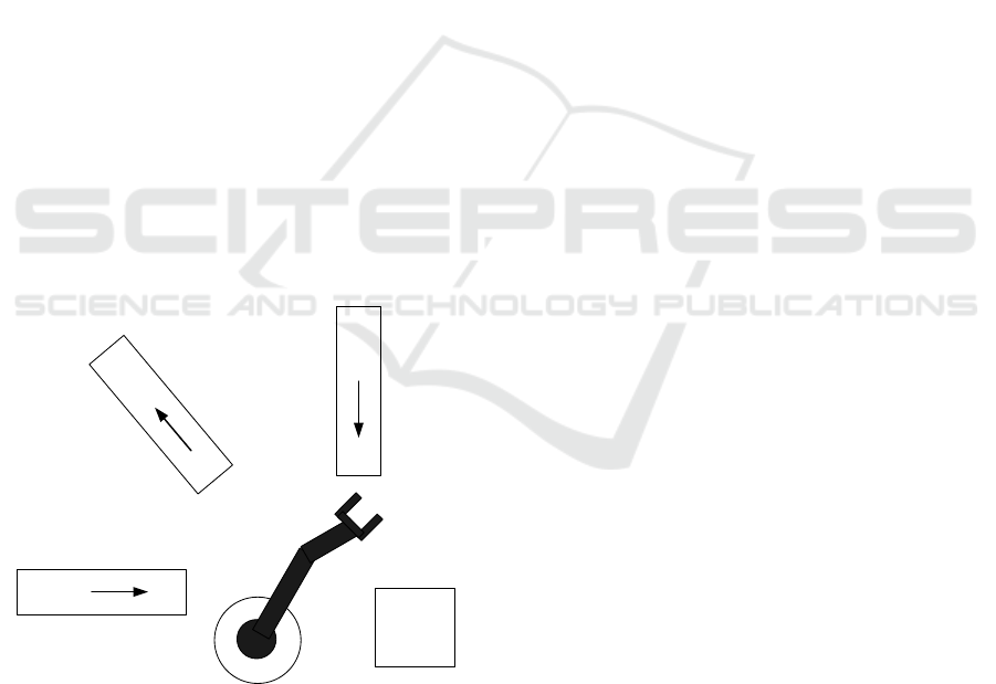
ticle. The RARM represented in the figure1 is compo-
sed of two inputs and one output conveyors, a servi-
cing robotic agent and a processing-assembling cen-
ter. Workpieces to be treated come irregularly one
by one. The workpieces of type A are delivered via
conveyor C1 and workpieces of the type B via the
conveyor C2. Only one workpiece can be on the
input conveyor. A robotic agent R transfers work-
pieces one after the other to the processing center.
The next workpiece can be put on the input conveyor
when it has been emptied by the robotic agent. The
technology of production requires that firstly an A-
workpiece is inserted into the center M and treated,
then a B-workpiece is added to the center, and finally
the two workpieces are assembled. Afterwards, the
assembled product is taken by the robot and put above
the C3 conveyer of output. The assembled product
can be transferred on C3 only when the output con-
veyor is empty and ready to receive the next produced
one.
A
Conveyor C1
A
B
C
o
n
v
e
y
o
r
C
3
B
Conveyor C2
Position p1
Position p2
Position p3 Position p4
P
osit
io
n
p
5
P
o
sitio
n
p6
Robot r
Processing unit
M
Figure 1: The benchmark production system RARM.
The system can be controlled using the following
actuators:
1. move the conveyor C1 (act1);
2. move the conveyor C2 (act2);
3. move the conveyor C3 (act3);
4. rotate robotic agent (act4);
5. move elevating the robotic agent arm vertically
(act5);
6. pick up and drop a piece with the robotic agent
arm (act6);
7. treat the workpiece (act7);
8. assembly two pieces (act8).
The robot-like agent receives the information from the
sensors as follows:
1. Is there an A-workpiece at the extreme end of the
position p1? (sens1)
2. Is C1 in its extreme left position? (sens2)
3. Is C1 in its extreme right position? (sens3)
4. Is there an A-workpiece at the unit M? (sens4)
5. Is C2 in its extreme left position? (sens5)
6. Is C2 in its extreme right position? (sens6)
7. Is there a B-workpiece at the extreme end of the
position p3? (sens7)
8. Is there a B-workpiece at the unit M? (sens8)
9. Is C3 in its extreme left position? (sens9)
10. Is C3 in its extreme right position? (sens10)
11. Is there a AB-workpiece at the unit M? (sens11)
12. Is the robotic agent arm in its lower position?
(sens12)
13. Is the robotic agent arm in its higher position?
(sens13)
3 SOFTWARE AGENT
ARCHITECTURE
We propose an agent-based architecture to control
embedded systems at run-time. The agent checks the
environment’s evolution and reacts when new events
occur.
3.1 Formal Specification
To describe the dynamic behavior of an intelligent
agent that dynamically controls the plant, we use the
state machine which can be defined as a state machine
whose states, inputs and outputs are enumerated.
The state machine is a graph of states and transiti-
ons. It treats the several events that may occur by
detecting them and responding to each one appropri-
ately. We define a state machine SM
i
as the following:
ICSOFT 2018 - 13th International Conference on Software Technologies
450

SM
i
= (S
i
, S
i0
, I
i
, O
i
, Precond
i
, Postcond
i
, t
i
)
• S
i
= {s
i1
, .., s
ip
}: the set of states;
• S
i0
the initial state;
• I
i
= {I
i1
, .., I
im
}: the input events;
• O
i
= {O
i1
, .., O
ik
}: the output events;
• Precond
i
: the set of conditions to be verified be-
fore the activation of a state;
• Postcond
i
: the set of conditions to be verified once
a state is activated;
• t
i
: S
i
× I
i
→ S
i
: the transition function.
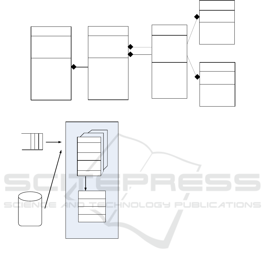
We propose a conceptual model for a state machine in
Figure 2 where we define the classes State machine,
State, Transition, Event and Condition. The State
Machine class contains a certain number of State and
Transition classes. This relation is represented by a
composition. The Transition class is double linked to
the State class because a transition is considered as an
association between two states. Each transition has
an event that is considered as a trigger to fire it and a
set of conditions to be verified. This association be-
tween the Transition class and the two classes Event
and Condition exists and it’s modeled by the aggrega-
tion relation.
3.2 Conceptual Architecture for MAS
We propose a generic architecture for MAS depicted
in Figure 3. This architecture consists of the follo-
wing parts: (i) the Event Queue to save different input
events that may take place in the system, (ii) the soft-
ware agent that reads an input event from the Event
Queue and reacts as soon as possible, (iii) the set of
state machines such that each one is composed of a
set of states, (iv) each state represents a specific infor-
mation about the system. The agent, based on state
machines, determines the new system’s state to exe-
cute according to event inputs and also conditions to
be satisfied. This solution has the following characte-
ristics: (i) The agent design is general enough to cope
with various kinds of embedded-software based ap-
plication. Therefore, the agent is uncoupled from the
application and from its components. (ii) The agent
is independent of the state machines: it permits to
change the structure of the state machine (add state
machines, change connections, change input events,
and so on) without having to change the implementa-
tion of the agent. This ensures that the agent continues
to work correctly even in case of modification of state
machines.
In the following algorithm, the symbol Q is an
event queue which holds incoming event instances, ev
refers to an event input, S
i
represents a State Machine,
and s
i, j
a state related to a State Machine S
i
. The in-
ternal behavior of the agent is defined as follow:
1. the agent reads the first event ev from the queue
Q;
2. searches from the top to the bottom in the different
state machines;
3. within the state machine SM
i
, the agent verifies
if ev is considered as an event input to the current
state s
i, j
(i.e. ev ∈ I related to s
i, j
). In this case, the
agent searches the states considered as successor
for the state s
i, j
(states in the same state machine
SM
i
or in another state machine SM
l
);
4. the agent executes the operations related to the
different states;
5. repeats the same steps (1-4) until no more event
exists in the queue to be treated.
Algorithm 1: GenericBehavior.
1: while Q.length() > 0 do
2: ev ← Q.Head()
3: for each state machine SM
i
do
4: s
i, j
← currentState
i
5: if ev ∈ I(s
i, j
) then
6: for each state s
i,k
∈ next(s
i, j
)
7: such that s
i,k
related to S
i
do
8: if execute(s
i,k
) then
9: currentState
i
← s
i,k
10: break
11: for each state s
l,k
∈ next(s
i, j
)
12: such that s
l,k
related to S
l
do
13: if execute(s
l,k
) then
14: currentState
l
← s
l,k
15: break
First of all, the agent evaluates the pre-condition
of the state s
i, j
. If it is false, then the agent exits, else
the agent determines the list of tasks to be executed.
Finally, it evaluates the post-condition of the state s
i, j
and generates errors whenever it is false.
Algorithm 2: Function execute(s
i, j
): boolean.
1: if ¬s
i, j
.PreCondition then
2: return false
3: else
4: listTask ← getInfo(s
i, j
.info)
5: for each task t ∈ listTask do
6: t.execute()
7: if ¬s
i, j
.PostCondition then
8: Generate error
9: return true
A Social Multi-agent Cooperation System based on Planning and Distributed Task Allocation: Real Case Study
451
State machine
# listStates
# initialState
# inputEvent
# outputEvent
+ nextState ()
+ setStates ()
+ setInputEvt ()
+ setOutputEvt ()
+ setInitialState ()
+ addState()
+ removeState ()
+ connectState ()
+ disconnectState ()
State
# stateID
# listEvents
# listConditions
+ setInputEvt ()
+ setOutputEvt ()
+ setInputCond()
+ setOutputCond ()
+ addEvent()
+ removeEvent()
+ addCondition()
+ removeCond ()
Event
# eventID
# immediate
+ setDescription()
+ getDescription ()
Condition
# conditionID
+ setDescription ()
+ getDescription()
*
1
Transition
# transitionID
# eventID
# conditionID
# initialStateID
# targetStateID
+ setEvent ()
+ setCondition()
+ addEvent()
+ removeEvent()
+ addCondition()
+ entry()
+ exit()
*
*
*
*
1
1
1
1
from
to
Figure 2: The Meta-model state machine.
Current state
Execution context
Current state
machine
...
...
Input Event
Resource
Agent description
Information about
current state
List of events
Execute()
NextState()
NextStateMachine ()
Figure 3: The internal agent behavior.
4 MULTI-AGENT PLANNING
4.1 Policy
To deal with the uncertainty and hesitancy problems,
we use conjunction operators for fuzzy relationship
as we mentioned before in (Ben Noureddine et al.,
2016). Here, it is very natural and reasonable to apply
a membership function in fuzzy mathematics to evalu-
ate the satisfaction degree of the plan (list of events).
G
s
is the problem goal, it is the union of individual
goals of all robot-like agents denoted by Sg_i, which
are flexible propositions.
G
s
= ∪
i=1..n
Sg_i (1)
These goals can be achieved with a certain satis-
faction degree. The form of a flexible proposition
is (ρ φ
1
, φ
2
,. . . , φ
j
κ
i
), where φ
i
∈ φ and κ
i
are ele-
ments of totally ordered set, K, which represents the
truth degree of the proposition. K is composed of a
finite number of membership degrees, k
↑
, k
1
,..., k
↓
,
where k
↑
∈ K and k
↓
∈ K, representing respectively
total falsehood and total truth. When dealing with a
flexible proposition with a truth value of k
↑
or k
↓
, the
boolean style ¬ (ρ φ
1
, φ
2
,. . . , φ
j
) or (ρ φ
1
, φ
2
,. . . , φ
j
)
is adopted. The flexible proposition (Miguel et al.,
2000) is described by a fuzzy relation, R, which is de-
fined as a membership function µ
R
(.): Φ
1
*Φ
2
*...*Φ
j
→K, where Φ
1
*Φ
2
*...*Φ
j
is the Cartesian product of
the subsets of Φ in the current proposition state. In
other words, if every agent achieves its individual go-
als with a certain satisfaction degree, the public goals
of the problem are achieved. The satisfaction degree
of a multi-agent flexible planning problem is defined
as the conjunction of the satisfaction degrees of each
action and goal.
µ
G
= ∧
i=1..n
µ
R
(i) (2)
The function µ
G
indicates how well a given plan is sa-
tisfying and can be considered as a value between 0
and 1, 1 stands for completely satisfied and 0 stands
for not satisfied at all. In our approach, each plan al-
ternative is associated with a satisfaction degree. That
means each value is the metric that provides the me-
ans to select a plan among different alternatives. Ha-
ving the ameliorated mean values calculated, the plan
alternative along with these values are sent to the cur-
rent state machine. The plan alternative, the need,
ICSOFT 2018 - 13th International Conference on Software Technologies
452
the goal and corresponding values reach the decision-
making mechanism first. The decision-making me-
chanism uses these values to compare the satisfaction
degrees for each plan alternative to find the most sa-
tisfactory one. The one with the highest satisfaction
degree is considered as the most satisfactory plan al-
ternative.
Running Example
Giving (S, A, G
s
) where S = {s
i
|i=1...n } is a set of sta-
tes, A= {Ci_le f t, Ci_right, Ri_le f t, Ri_right, take
i
,
load
i
, put
i
, process
i
|i=1...n } is a set of actions, and
G
s
is the problem goal. if s
0
and g = {workpiece in
the processing unit}. Let:
• π
0
: (C2_le f t, take
2
, load
2
, process
2
)
• π
1
: (load
1
, put
1
, process
1
, C1_right)
• π
2
: (C1_le f t, take
1
, load
1
, put
1
, process
1
,
C1_right)
We solve multi-agent planning problems by distri-
buted flexible constraint satisfaction problem (CSP)
technique (Miguel and Giret, 2008) and make a trade-
off between plan length and the compromise decisi-
ons made. The quality of a plan is measured by its
satisfaction degree and its length, where the shorter
of two plans is better under the same satisfaction de-
grees. In this example, the definitions of K and L are:
K = {k
↑
, k
1
, k
2
, k
↓
}, L= {l
↑
, l
1
, l
2
, l
↓
}. The multi-agent
planning problem is helpful to robot-like agents like
in this example. If any actions ∈ {Ci_le f t, Ci_right,
Ri_le f t, Ri_right, take
i
, load
i
, put
i
, process
i
|i=2...n }
will damage the plan, leading to a satisfaction degree
l
2
, any plan not beginning with C1_le f t will result in
a satisfaction degree l
2
because it is not applicable to
s
0
, and when any action is applicable to s
0
and the
resulting state is a goal state then the result will be
a satisfaction l
1
. We may obtain more than one plan
with different satisfactions by different compromises
as shown in Table 1 and 2.
Table 1: A plan of 4 steps with satisfaction l
2
.
Action No Action Satisfaction
1 C2_le f t l
2
2 take
2
l
2
3 load
2
l
2
4 process
2
l
2
Then π
0
is not a solution because although it is
applicable to s
0
, the resulting state is not a goal state;
π
1
is not a solution because it’s not applicable to s
0
;
π
2
is the most appropriate solution.
4.2 Evaluation
In this paper, we propose an architecture that inte-
grates conjunction operators for fuzzy relationship to
Table 2: A plan of 6 steps with satisfaction l
↑
.
Action No Action Satisfaction
1 C1_le f t l
↑
2 take
1
l
↑
3 load
1
l
↑
4 put
1
l
↑
5 process
1
l
↑
6 C1_right l
↑
evaluate the satisfaction degree of the plan, this reli-
able technique can offers robust and reliable soluti-
ons for the planning problem. The aim of the expe-
riment we have done was to find out how our soft-
ware architecture having different facilities and abili-
ties can perform, simulate robot-like agent’s behavior,
and how the performance of the robotic agents was in-
fluenced by varying their satisfaction degree and the
plan length. In order to show the feasibility of our
approach, we present experimental results on preli-
minary tests focusing on the analysis of the planning
performance using the satisfaction degree by simula-
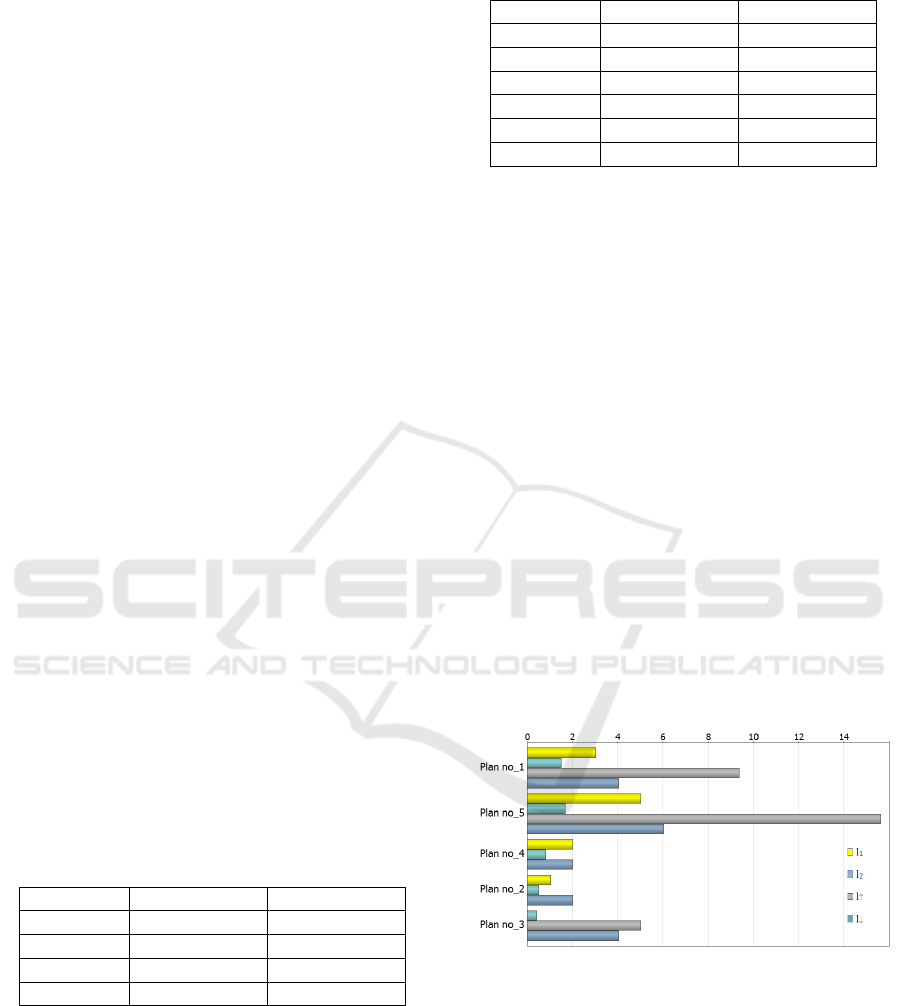
ting RARM. Figure 4 shows the results obtained when
running our architecture. Therefore, we compare their
performance on a set of plans for the RARM state-
transitions. Since the second plan of 2 steps with max-
imum satisfaction degree l
2
, the fifth plan of 15 steps
with satisfaction l
↑
. So, it is often possible to find
short, satisfactory plans quickly during the decision-
making mechanism. The quality of a plan is its sa-
tisfaction degree combined with its length, where the
shorter of two plans with equivalent satisfaction de-
grees is better.
Figure 4: Experimental results collected plan length and the
satisfaction degree.
These results are indicative of the ability to dy-
namically treat operating conditions among different
conveyors, a service robot and a treating-assembling
center over time, plays a critical role in the actions
selection during the planning. Further, making de-
cisions also affect the choice of process flexibility.
According to the software architecture, breakdown
of an individual robotic agent will have little effect
A Social Multi-agent Cooperation System based on Planning and Distributed Task Allocation: Real Case Study
453

on the whole team, because of the existence of the
technique satisfaction degree of the plan which sim-
plify the choice of the most satisfactory plan alterna-
tive. When the architecture is applied to multi-robot
system RARM, there are several important functions
that have been performed. The associated issues are
planning and intelligent decision making.
5 DISTRIBUTED TASK
ALLOCATION APPROACH
5.1 Problem Definition
We describe in this section the social task allocation
problem which can be defined as an agent not ade-
quate to complete a task by itself and it needs the
cooperation from other agents to achieve an action or
service. We denote A = {a
1
,..., a
m
} a set of agents,
that require resources to achieve tasks; and we denote
R = {r
1
,..., r
k
} a set of resources types available to A.
Each agent a ∈ A controls a fixed quantity of resour-
ces for each resource type in R, which is defined by
a resource function: rsc : A × R → N. Moreover, we
assume agents are connected by a social network as
discussed before in (Ben Noureddine et al., 2017).
Definition 1 (Social Network). An agent social net-
work SN = (A, AE) is an undirected graph, where A
is a set of agents and AE is a set of edges connecting
two agents a
i
and a
j
significant that it exists a social
connection between these two agents.
We define T = {t
1
, t
2
,..., t
n
} a set of needed tasks
at such an agent social network. Each task t ∈ T is
then defined by a 3-tuple {u(t), rsc(t), loc(t)}, where
u(t) is the utility gained if task t is accomplished, rsc:
T × R → N is the resource function that specifies the
amount of resources required for the accomplishment
of task t and loc: T → A is the location function that
defines the locations (i.e., agents) at which the tasks
arrive in the social network. An agent a is the location
of a task t, i.e. loc(t) = a, is called this task manager.
Each task t ∈ T needs some specific resources from
the agents to complete the task. A task allocation is
defined as the exact assignment of tasks to agents.
A task plan of agent consists of a list of actions to
be taken in order. Each action is an attempt to acquire
a particular resource, by asking the agent associated
with that resource for permission to use the resource.
A task agent builds a plan by maximizing the satis-
faction degree described in the section 4. At each
timestep, a task agent performs the action presently
prescribed by its plan. It does this by contacting the
agent associated with the targeted resource, and as-
king it whether it may take the resource.
Definition 2 (Multi-agent Planning Problem). We
denote π a plan which is described by a 5-tuple
{T, P(t), E(t), G, µ
t
}, where T is a set of tasks as men-
tioned above, P(t) is the set of action (task) precondi-
tions, E(t) is the set of task effects, G is the problem
goal and µ
t
the satisfaction degree of a multi-agent
flexible planning problem introduced in section 4.
Definition 3. Each agent a ∈ A is composed of 4-tuple
{AgentID(a), Neig(a), Resource(a), State(a) }, where
AgentID(a) is the identity of agent a, Neig(a) is a set
indicating the neighbors of agent a, Resource(a) is
the resource which agent a contains, and State(a) de-
monstrates the state of agent which will be described
in the following subsection.
Definition 4 (Task Allocation). We consider a set of
tasks T = {t
1
, t
2
,..., t
n
}, a set of agents A = {a
1
,..., a
m
},
a set of plans π = {π
1
,..., π
m
}, and a set of resources R
= {r
1
,..., r
k
} in a social network SN, a task allocation
is a mapping φ : T × A × R × π → SN.
5.2 The Principle of Distributed Task
Allocation
To guarantee a coherent behavior of the whole distri-
buted system, we define the following idea: we sup-
pose that Neig(a
i
) stores only directly linked neig-
hboring agents of agent a
i
where at each timestep,
these task neighboring agents perform the action pre-
sently prescribed by their most satisfying tasks. The
task neighboring agents do this by contacting the
agent associated with the targeted resource, and as-
king it whether it may take the resource.
To control system in our multi-agent architecture,
we introduce three types of agents like in (Ben Nou-
reddine et al., 2017): Manager is the agent which re-
quests help for its task, the agent which accepts and
performs the announced task is called Participant and
Mediator is the agent that receives another agent’s
commitments for assistance to find participants.
We propose a software multi-agent architecture
to handle distributed task allocation. To guaran-
tee a coherent behavior of the whole distributed sy-
stem, we define the following idea: we suppose
that Neig(a
i
) stores only directly linked neighboring
agents of agent a
i
.
We define as in (Ben Noureddine et al., 2017)
three states States = {Busy, Committed, Idle} in a
complex adaptive system and an agent can be only in
one of the three states at any timestep. When an agent
is a Manager or Participant, the state of that agent is
Busy. When an agent is a Mediator, the agent is in
Committed state. An agent in Idle state is available
and not assigned or committed to any task.
ICSOFT 2018 - 13th International Conference on Software Technologies
454

For efficient task allocation, it is supposed that
only an Idle agent can be assigned to a new task as
a Manager or a partial fulfilled task as a Participant,
or Committed to a partial fulfilled task as a Mediator.
A partial fulfilled task is a task, for which a full group
is in formation procedure and has not yet formed.
We present our approach which describes an inte-
ractive model between agents detailed as follows:
• When a Manager denoted by A
Mn
ought to apply
distributed task allocation, it then sends resource
announce messages described formally as Re-
sAnnounceMess = <AgentID(A
Mn
), TaskID(t
Mn
),
Resource(t
Mn
)>, to all its neighbors;
• These neighboring agents receiving the ResAn-
nounceMess sent by A
Mn
,
– If (state(neighboring agent) = Idle) Then
the neighboring agent A
j
applies the single-
agent planning to select the most appropri-
ate tasks and then proposes with information
about the types of resources it contains, the
execution time, the utility and the identities of
them, namely ProposeMess = <AgentID(A
j
),
Resource(A
j
), Execute(A
j
), Utility(A
j
)>.
– Else (state(neighboring agent) = Busy)
the neighboring agent A
j
refuses and
sends the following message RefuseMess
= <AgentID(A
j
)>.
• After answering the resource announce messages
sent by A
Mn
– If (A
Mn
is satisfied with many resource propo-
sals of the neighbor) Then A
Mn
will pick the
agent having the highest utility, denoted by A
j
,
and the state of A
j
will be changed to Busy. In
case the A
Mn
finds many agents having the hig-
hest utility then it chooses the agent A
j
propo-
sing the least execution time with a most appro-
priate task.
– Else the A
Mn
is satisfied with only one resource
of the neighbor, then the A
Mn
will choose this
agent without any utility consideration.
A
Mn
sends a contract to the chosen agent A
j
com-
posed of 4-tuple, Contract = <AgentID(A
Mn
),
AgentID(A
j
), TaskID(t
Mn
), Resource(A
Mn
)>.
• After obtaining the answer from its diffe-
rent cooperative neighbors, A
Mn
then compares
the available resources from its neighbors, i.e.
Resoneig(A
Mn
), with the resources required for its
task t
Mn
, namely rsc(t
Mn
). (Here, Resoneig(A
Mn
)
=
S
A
j
∈Neig(A
Mn
)
Resource(A
j
)). This comparison
would result in one of the following two cases:
1. If (rsc(t
Mn
) ⊆ Resoneig(A)) Then A
Mn
can
form a full group for task t
Mn
directly with its
neighboring agents which they apply the policy
of single-agent planning.
2. Else (Resoneig(A) ⊂ rsc(t
Mn
)), in this condi-
tion, A
Mn
can only form a partial group for task
t
Mn
. It then commits the task t
Mn
to one of its
neighbors. The commitment selection is based
on the number of neighbors each neighbor of
A
Mn
maintaining. The more neighbors an agent
has, the higher probability that agent could be
selected as a Mediator agent to commit the task
t
Mn
.
• After selection, A
Mn
commits its partial fulfil-
led task t
Mn
to the Mediator agent, denoted
as A
Md
. A commitment consists of 4-tuple,
Commitment = <AgentID(A
Mn
), AgentID(A
Md
),
TaskID(t
Mn
), rsc(t
Mn
)
1
>, where rsc(t
Mn
)
1
is a
subset of rsc(t
Mn
), which contains the unfulfilled
required resources. Afterwards, A
Md
subtracts 1
from N
max
and attempts to discover the agents
with available resources from its neighbors. If
any agents satisfy resource requirement, A
Md
will
send a response message, RespMess, back to A
Mn
.
The agent A
Mn
then directly makes contract with
the agents which satisfy the resource requirement
and have an appropriate plan of tasks. If the neig-
hboring agents of A
Md
cannot satisfy the resource
requirement either, A
Md
will commit the partial
fulfilled task t
Mn
to one of its neighbors again.
• This process will continue until all of the resource
requirements of task t
Mn
are satisfied, or the N
max
reaches 0, or there is no more Idle agent among
the neighbors. Both of the last two conditions, i.e.
N
max
= 0 and no more Idle agent, demonstrates
the failure of task allocation. In these two conditi-
ons, A
Mn
disables the assigned contracts with the
Participant s, and the states of these Participant
are reset to Idle.
• When finishing an allocation for one task, the sy-
stem is restored to its original status and each
agent’s state is reset to Idle.
Algorithm Communicate()
begin
switch (role)
case Manager:
switch (step)
case 0: // send a request to all neighbors Agents
for j = 1 to NbA do
send(ResAnnounceMes(Agents[j]));
step++;
break;
case 1: // Receive accept/refusal from neighbors Agents
reply ← receive();
if (reply = ProposeMess(Agents[j]))
A Social Multi-agent Cooperation System based on Planning and Distributed Task Allocation: Real Case Study
455

send(Contract(Agents[j]));
Res=Res+Res(Agents[j]);
Nb++;
if (Nb = NbA )
if (Res = Resource)
step ← 4; (execute step)
else
step ++;
break;
case 2: // choose the Mediator Agent
Max ← Neig(Agents[1])
Mediator ← 1
for j = 2 to NbA do
if Neig(Agents[j]) > Max ;
Mediator ← j
send(Commitment(Agents[Mediator]));
step++;
case 3: // wait the response from the Mediator Agent
reply ← receive();
if (reply = ResMess(Agents[Mediator]))
for j = 1 to list(Agents[Mediator]) do
send(Contract(Agents[j]));
Res += Res(list(Agents[Mediator]))
if (Res = Resource)
step ← 4; (execute step)
else
step ← 5; (cancel step)
break;
case 4:
for j = 1 to length(list(Agents)) do
send(Execute(list(Agents[j]));
step ← 0;
role ← participant;
break;
case 5:
step ← 0;
role ← participant;
break;
End switch
case Mediator:
switch (step)
case 0: // wait a message from the Manager Agent
reply ← receive();
if (reply = Commitment)
step++;
break;
case 1: // send a request to all neighbors Agents
for j = 1 to NbA do
send(ResAnnounceMes(Agents[j]));
step++;
break;
case 2: // Receive accept/refusal from neighbors Agents
reply ← receive();
if (reply = ProposeMess(Agents[j]))
Res=Res+Res(Agents[j]);
Nb++;
if (Nb = NbA )
step ← 3; (inform the manager)
break;
case 3: // inform the manager Agent
send(ResMess(Manager));
break;
End switch
case Participant:
switch (step)
case 0: // wait a message from the Manager Agent
reply ← receive();
if (reply = ResAnnounceMes(Manager))
if (state = IDLE )
send(ProposeMess(Manager));
step++;
else
step ← 0;
break;
case 1: // wait a CONTRACT from the Manager Agent
reply ← receive();
if (reply = CONTRACT(Manager))
state = BUSY
step++;
break;
case 2: // Receive accept/refusal from neighbors Agents
reply ← receive();
if (reply = Execute(Manager))
ExcuteTask();
state = IDLE
step← 0;
break;
End switch
end
5.3 Experiments
In order to strengthen the validity and to demonstrate
the quality of our approach, we have simulated our
distributed task allocation algorithm in different net-
works. To test the efficiency of our algorithm, we
compare it with the Greedy Distributed Allocation
Protocol (GDAP) (Weerdt et al., 2007). In this sub-
section, we briefly define GDAP. Then, we introduce
the experiment environment’ settings. And we depict
in the last sub-subsection the results and the relevant
analysis.
5.3.1 Greedy Distributed Allocation Protocol
GDAP is selected to handle task allocation problem
in agent social networks. It’s described briefly in
(Weerdt et al., 2007) as follows: All Manager agents
a ∈ A try to find neighboring contractors (the same
as Participant in this paper) to help them do their
tasks T
a
= {t
i
∈ T |loc(t
i
) = a}. They start offering
the most efficient task. Among all tasks offered, con-
tractors select the one having the highest efficiency
and send a bid to the related manager. A bid con-
sists of all the resources the agent is able to supply
for this task. If sufficient resources have been offe-
red, the manager selects the required resources and
informs all contractors of its choice. When a task is
allocated, or when a manager has received offers from
all neighbors but still cannot satisfy its task, the task
ICSOFT 2018 - 13th International Conference on Software Technologies
456
is removed from its task list. And this is the main dis-
advantage of GDAP that it only relies on neighbors
which may cause several unallocated tasks due to li-
mited resources, that is exactly what our approach
tries to solve.
5.3.2 Experimental Settings
We have been implementing our distributed task allo-
cation algorithm and (GDAP) in JAVA and we have
been testing them. There are two different settings
used in our experiment. The first setup has been done
in the Small-world networks in which most neighbors
of an agent are also connected to each other. The se-
cond setup has been done in the Scale free networks.
Setting 1: we consider the number of agents 40, the
number of tasks 20, the number of different resource’s
types 5, the average number of resources required by
each task 30 and the average number of resources nee-
ded by each tasks 30. We assume that tasks are dis-
tributed uniformly on each IDLE agent and resources
are normally allocated to agents. The only changing
variable in this setting is the average number of neig-
hbors. This setting intends to represent the influence
of neighbors’ number on the performance of both our
algorithm and GDAP.
Setting 2: we fix the average number of neighbors at
10. We consider that the number of agents increases
and varies from 100 to 2000. We fix the ratio between
the number of agents and tasks at 5/3 and the resource
ratio at 1.2. The number of different resource types is
20 and the average resource requirement of tasks is
100. The tasks are uniformly distributed. This setting
is defined to demonstrate the scalability of both our
algorithm and GDAP in a large scale networks with a
fixed average number of neighbors.
The algorithms have been evaluated according to two
criteria in this experiment; the Utility Ratio and the
Execution Time, where:
UtilityRatio =
∑
Success f ul − completed − tasks
Total − o f −tasks
(3)
The unit of Execution Time is millisecond. For sim-
plicity, we suppose that once a task has been allocated
to a Participant, the Participant would successfully fi-
nish this task without failure.
5.3.3 Experiment Results and Analysis
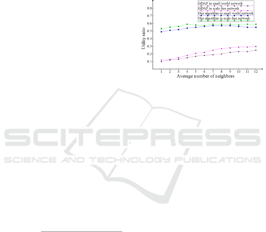
Experiment Results and Analysis from Setting 1: we
would like to test in this experiment the influence of
different average number of neighbors on both algo-
rithms. We notice in Figure 5 that the Utility Ratio
of our algorithm in different networks is more relia-
ble than the GDAP algorithm. For the reason that the
distribution of tasks in GDAP is only depending on
the Manager neighbors, contrary to ours, in the case
of need, other agents are allocated (i.e. not only the
neighbors).
Figure 5: The Utility ratio of the GDAP and our algorithm
depending on the average number of neighbors in different
type of networks.
We can mention another factor to compare both
approaches which is the network type. The results of
GDAP in a small world network is higher than in a
scale free network, and this could be explained by the
fact that the most agents have a very few neighbors in
the small network. Opposingly to that , in the scale
free network when the average number of neighbors
increases, the GDAP performance decreases. Which
leads to say that this factor does not affect the perfor-
mance of our algorithm as we take into consideration
enough neighbors to obtain satisfactory resources for
processing its tasks without reallocating tasks further.
Figure 6 presents the Execution Time of two algo-
rithms in different networks depending on the average
number of neighbors. The Execution Time of our
algorithm is higher than that of GDAP since du-
ring execution, the agents in our algorithm reallocate
tasks when resources from neighbors are unsatisfying.
Furthermore, we note that the results of GDAP in a
small world network is higher than in a scale free net-
work, but compared to our algorithm are still lower
and this is because it considers only neighbors which
could decrease the time and communication cost du-
ring task allocation process.
Experiment Results and Analysis from Setting 2: we
would like to test the scalability of both GDAP and
our algorithm in different large network scales like ap-
plications running on the internet. The Figure 7 pre-
sents the Utility Ratio of GDAP which is constantly
descending while that of our algorithm can save the
stability and it is higher than GDAP with the increase
of number of agents and simultaneously the number
A Social Multi-agent Cooperation System based on Planning and Distributed Task Allocation: Real Case Study
457
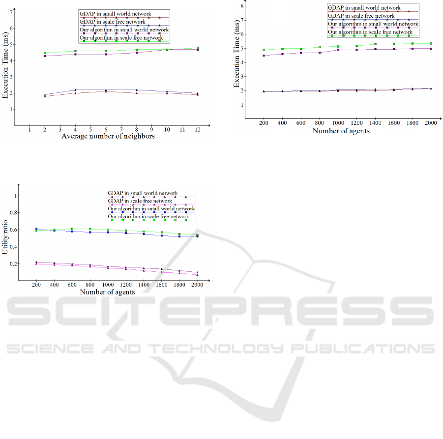
Figure 6: The Execution time in millisecond of the GDAP
and our algorithm depending on the average number of
neighbors in different type of networks.
Figure 7: The Utility ratio of the GDAP and our algorithm
depending on the number of agents in different type of net-
works.
of tasks in a large network scale. In fact, we can ex-
plain this by the proportional rise of the network scale,
the tasks and the resource types.
Moreover the condition in small world network is
better than that in scale free network. And this is justi-
fied by the same reason described above, that in scale
free network, several agents only have a few neig-
hbors which is not good for GDAP. Compared with
GDAP, our algorithm is more competitive and it is fa-
voured from task reallocation.
Figure 8 presents the Execution Time of our algo-
rithm and GDAP in different network types. GDAP
spends less time when there are more agents in the
network. This is because there are more tasks despite
the average number of neighbors is fixed. Accor-
dingly, more reallocation steps cannot be avoided to-
wards allocating these tasks, that leads to soaring in
time and overhead communication. Furthermore, the
graphs show that the GDAP and our algorithm almost
behaves linearly and the time consumption of GDAP
keeps a lower level than ours. This can be suppo-
sedly interpreted that GDAP only relies on neighbo-
ring agents.
Figure 8: The Execution time in millisecond of the GDAP
and our algorithm depending on the number of agents in
different type of networks.
6 CONCLUSION
Cooperation is a key process for multi-agent system’s
research and, as such, it has received a considerable
amount of attention in literature. In this paper we
propose an agent-based architecture to manage ser-
vices, handle and control embedded systems at run-
time to perform self-adaptation. An important origi-
nality of our work is the integration of the fuzzy lo-
gic technique to select plans in the planning phase, in
which a great attention is payed in this paper. All the
results are applied in this phase to a particular ben-
chmark production system. We also put forward a
distributed method to solve multi-task allocation pro-
blems in the MAS. Although our approach overcomes
many dilemmas, which exist in some current related
works, due to its decentralization and reallocation fe-
atures, it still has several deficiencies. They will be
faced in near future work, that will focus on asses-
sing the mechanism’s ability to deal with larger state
action spaces than the one exemplified in this paper
and review the performance benefits compared to the
heavier-weight alternative solutions.
REFERENCES
Ben Noureddine, D., Gharbi, A., and Ben Ahmed, S.
(2016). An approach for multi-robot system based
on agent layered architecture. International Jour-
nal of Management and Applied Science (IJMAS),
2(12):135–143.
Ben Noureddine, D., Gharbi, A., and Ben Ahmed, S.
(2017). Multi-agent deep reinforcement learning for
task allocation in dynamic environment. In In the Pro-
ceedings of the 12th International Conference on Soft-
ware Technologies (ICSOFT’17), pages 17–26.
Das, G. P., McGinnity, T. M., Coleman, S. A., and Behera,
L. (2014). A distributed task allocation algorithm for
ICSOFT 2018 - 13th International Conference on Software Technologies
458

a multi-robot system in healthcare facilities. Springer
Journal of Intelligent and Robotic Systems, 84:1–26.
Del Val, E., Rebollo, M., and Botti, V. (2013). Promo-
ting cooperation in service-oriented mas through so-
cial plasticity and incentives. Journal of Systems and
Software, 86:520–537.
Gharbi, A., Ben Noureddine, D., and Ben Hlima, N. (2015).
Building multi-robot system based on five capabilities
model. In In the Proceedings of the 12th Internatio-
nal Conference on Evaluation of Novel Approaches to
Software Engineering (ENASE’15), pages 270–275.
Hruz, B. and Zhou, M. (2007). Modeling and control of
discrete-event dynamic systems with petri nets and ot-
her tools. pages 67–78.
Jennings, N. R., Sycara, K., and Wooldridgse, M. (1998). A
roadmap of agent research and development. Autono-
mous agents and multi-agent systems, 1:7–38.
Mejia, M., Peña, N., Muñoz, J. L., Esparza, O., and Alzate,
M. (2012). Decade: Distributed emergent cooperation
through adaptive evolution in mobile ad hoc networks.
Ad Hoc Networks, 10:1379–1398.
Miguel, I. and Giret, A. (2008). Feasible distributed csp
models for scheduling problems. Engineering Appli-
cations of Artificial Intelligence.
Miguel, I., Jarvis, P., and Shen, Q. (2000). Flexible graph-
plan. In In the Proceedings of the 14th European Con-
ference on Artificial Intelligence, Berlin, pages 4506–
4514.
Sun, Q., Garcia-Molina, H., and Ben Ahmed, S. (2004).
Slic: A selfish linkbased incentive mechanism for un-
structured peer-to-peer networks. In In the Procee-
dings of the 24th International Conference in Distri-
buted Computing Systems, pages 506–515.
Weerdt, M., Zhang, Y., and Klos, T. (2007). Distributed task
allocation in social networks. In In the Proceedings of
the 6th Autonomous Agents and Multi-agent Systems
(AAMAS 2007), Honolulu, Hawaii, USA, pages 500—
-507.
Wei, G., Zhu, P., Vasilakos, A. V., Mao, Y., Luo, J.,
and Ling, Y. (2013). Cooperation dynamics on col-
laborative social networks of heterogeneous popula-
tion. IEEE Journal Selected Areas in Communicati-
ons, 31:1135–1146.
A Social Multi-agent Cooperation System based on Planning and Distributed Task Allocation: Real Case Study
459
