
Test Evaluation and Computational Modeling Applicability for
Compression Moldability of Inert Explosive
Jin Sung Lee and Jung Su Park
Agency for Defense Development, Yuseong P.O. Box 35-4, Daejeon, South Korea
Keywords: Shima-Oyane Yield Model, Powder, Moldability Behaviour, Double Action Pressing, Isostatic Pressing,
Computational Model Analysis.
Abstract: Using an inert explosive powder, molding experiments were carried out. And a computational model analysis
was performed to predict moldability behaviour of an inert explosive powder. In order to analysis the Shima-
Oyane yield model to predict the behaviour of the densification for inert explosive powder, using an inert
explosive powder was carried out moldability tests on the pressure, could be obtained volumetric strain on
the pressure, relative density and so on. Based on the results of the curve fitting, it could be derived the
parameters for the yield function of the cap with the critical state. Finite element analysis for both double
action pressing and isostatic pressing process of the two yield models were performed. And changes in relative
density and densification behaviour of an inert explosive powder were analysed. In addition, it investigated
the distribution of the relative density or volumetric strain caused by the overall and local variations. It was
founded the maximum stress and position etc. under working pressure of inert explosive powder.
1 INTRODUCTION
In the manufacturing technologies of P/M products,
isostatic pressing and die compression are widely
used. However, P/M parts formed by die compression
have inhomogeneous density distributions due to the
friction between the powder and die wall.
Process simulations by using a finite element
analysis may be useful to control the shape during
P/M forming process (Lewis, 1993), (Gethin, 1994).
The numerical modelling of the powder compression
process requires the appreciate constitutive models
for densification of a powder material. A number of
yield functions have been developed for densification
behaviour of powder material, so far.
By including the effect of hydrostatic stress on
plastic deformations of porous materials (Kuhn and
Downey, 1971), (Shima-Oyane, 1976), and
(Doraivelu et al., 1984) proposed yield functions from
uniaxial tests of powder compressions. (Fleck et
al.,1992) proposed a microscopic constitutive model
from particle deformations. The yield function by
Fleck et al., however, did not agree well with
experimental data of soft metal powder during die
compaction (Kwon, 1997). A number of researchers
also adopted models for densification of powder from
soil mechanics. Watson et al., (1993) investigated
yield criteria of powder by using the Drucker-Prager-
/Cap model.
In this paper, using an inert explosive powder as a
soft powder material, molding experiments were
carried out. And a computational model analysis was
performed to predict moldability behaviour of an inert
explosive powder.
To apply Shima-Oyane, Drucker-Prager/Cap
yield model to predict the behaviour of the
densification for inert explosive powder, using an
inert explosive powder were carried out moldability
tests. Finite element analysis for double action
pressing and isostatic pressing process were
performed.
2 ANALYSIS
2.1 Constitutive Model
In die compression, the deformation behaviour of the
powder body is based on the yield criterion. Unlike
bulk solids, the yield criterion includes the
hydrostatic pressure due to volume change in
compression. Among many yield criteria for
Lee, J. and Park, J.
Test Evaluation and Computational Modeling Applicability for Compression Moldability of Inert Explosive.
DOI: 10.5220/0006832504290434
In Proceedings of 8th International Conference on Simulation and Modeling Methodologies, Technologies and Applications (SIMULTECH 2018), pages 429-434
ISBN: 978-989-758-323-0
Copyright © 2018 by SCITEPRESS – Science and Technology Publications, Lda. All rights reserved
429
compression, Shima-Oyane’s criteria is of the
generalized form
(1)
Where, q and p are the effective stress and hydrostatic
pressure, is relative density
is the flow stress of
matrix material. c, and m are the material
parameters.
The complicated procedure to determine the
material parameters including the flow stress of
matrix material
and the friction coefficient has
obstructed the practical use of the numerical
simulation in the process. In this paper, we tried to
find the material parameters, from the die
compression test. We assumed the following
expression for the flow stress of matrix material
:
(2)
Where, a, b, and n are the material parameters and
is the effective strain of matrix material.
2.2 Damage Model
In die compression process, crack formulation during
compression and ejection is very important problem.
In this paper, we used Shima-Oyane yield model and
Drucker-Prager failure surface for the crack
formulation. Shima-Oyane model is elliptical shape
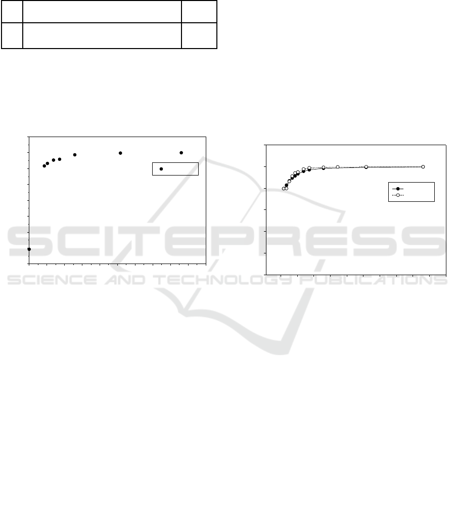
in the stress space as shown figure 1.
A new concept for crack formulation, failure
separation length(FSL), can be considered. FSL
means the accumulated separation length from
Drucker-Prager failure surface as shown in figure 1.
**FSL : Failure Separation Length
Figure 1: Shima-Oyane yield surface and Drucker-Prager
failure surface.
During the numerical simulation of die
compression process, we can investigate the stress
path of all elements and we can check whether a
specific region go over the Drucker-Prager failure
surface. The accumulated separation length from
Drucker-Prager failure surface can show the possibi-
lity of crack formulation.
Finite element calculations were obtained by
using Shima-Oyane model in the constitutive library
provide in PMsolver S/W.
3 EXPERIMENTS
3.1 Test Equipment
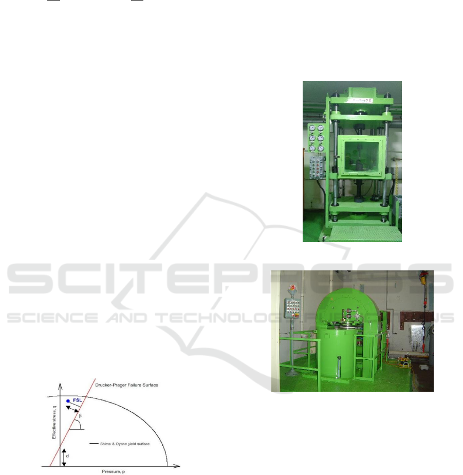
Figure 2: Hydraulic press.
Figure 3: Isostatic press.
The test equipment for this study are double action
hydraulic press and isostatic press. Double action
press in figure 2 was used to test the pressing of a
cylindrical shaped body to compare with the results
of computational analysis, the compression
moldability evaluation test to check the density
against various pressures, and the friction coefficient.
Isostatic press in figure 3 was used to make
shaped body for comparison with computational
analysis results.
3.2 Determination of Material
Parameters
Compression moldability is evaluated by using inert
SIMULTECH 2018 - 8th International Conference on Simulation and Modeling Methodologies, Technologies and Applications
430
explosive and a suitable compression molding
simulation model is presented. The composition used
for the test was compression molded at room
temperature as shown in table 1.
Table 1: Inert explosive composition.
No.
Composition(wt.%)
TMD
(g/cm
3
)
1
CaCO
3
/Pentaerythritol/(NH
4
)
2
SO
4
/Binder
system = 22/6/64/8
1.746
** TMD: Theoretical Maximum Density(g/cm
3
)
Die compression response of inert explosive
powder was investigated in a closed die under double
action pressing. The inert explosive powder was
pressed under axial pressure from 4.74 to 173 MPa as
shown in figure 4.
Figure 4: Variation of relative density with pressure of inert
explosive powder for various pressures (TMD = 1.746
g/cm
3
).
In this work, we used the same material
parameters c and that Shima-Oyane used for the
iron based powder as follows:
c = 6.20, =1.028
(3)
The material parameter m and the flow stress of
matrix material
were obtained by minimizing the
difference between the calculation and the measured
variation of relative density with pressure during the
die compression process without friction effect. The
material parameter m and the flow stress of matrix
material were determined as follows:
m = 4.1109
(4)
Where, a = 14.1248, b = 0.0001, and n = 11.358
Die compression tests were performed with two
different methods to get the pressure-density response
of the inert explosive powder without and with
friction effect as shown in figure 5.
To investigate the relation between the relative
density and pressure of the inert explosive powder
without the friction effect, silicone type lubricant was
applied on the die wall and small amount of
powder(15g) was poured in a closed with 36 mm in
diameter. The big amount(45g) of inert explosive
powder used to test friction effect.
It was found that specimen(15g) had a slightly
higher density than specimen(47g) in the low pressure
region, and the density difference between the two
specimens disappeared with increasing pressure. At
the final pressure of 173 MPa, the relative density of
the two specimens was 0.99, which was the same
value.
Figure 5: Variation of relative density with pressure of inert
explosive powder under frictional condition during double
action pressing.
Figure 6 shows variation of relative density with
pressure of inert explosive during die compression.
The friction coefficient between the inert explosive
powder and the mold was varied through
computational analysis to obtain the friction
coefficient with the pressure and relative density
curve shown in the experiment.
The friction coefficient was obtained by
minimizing the difference between the finite element
simulation results with the determined material
parameters in Eqs. (3) and (4) and the measured
variation of relative density with pressure during the
die compression process with friction.
Pressure(MPa)
0 20 40 60 80 100 120 140 160 180 200
Relative Density
0.3
0.4
0.5
0.6
0.7
0.8
0.9
1.0
1.1
Experiment
Pressure(MPa)
0 20 40 60 80 100 120 140 160 180 200
Relative Density
0.5
0.6
0.7
0.8
0.9
1.0
1.1
Friction
No Friction
Test Evaluation and Computational Modeling Applicability for Compression Moldability of Inert Explosive
431
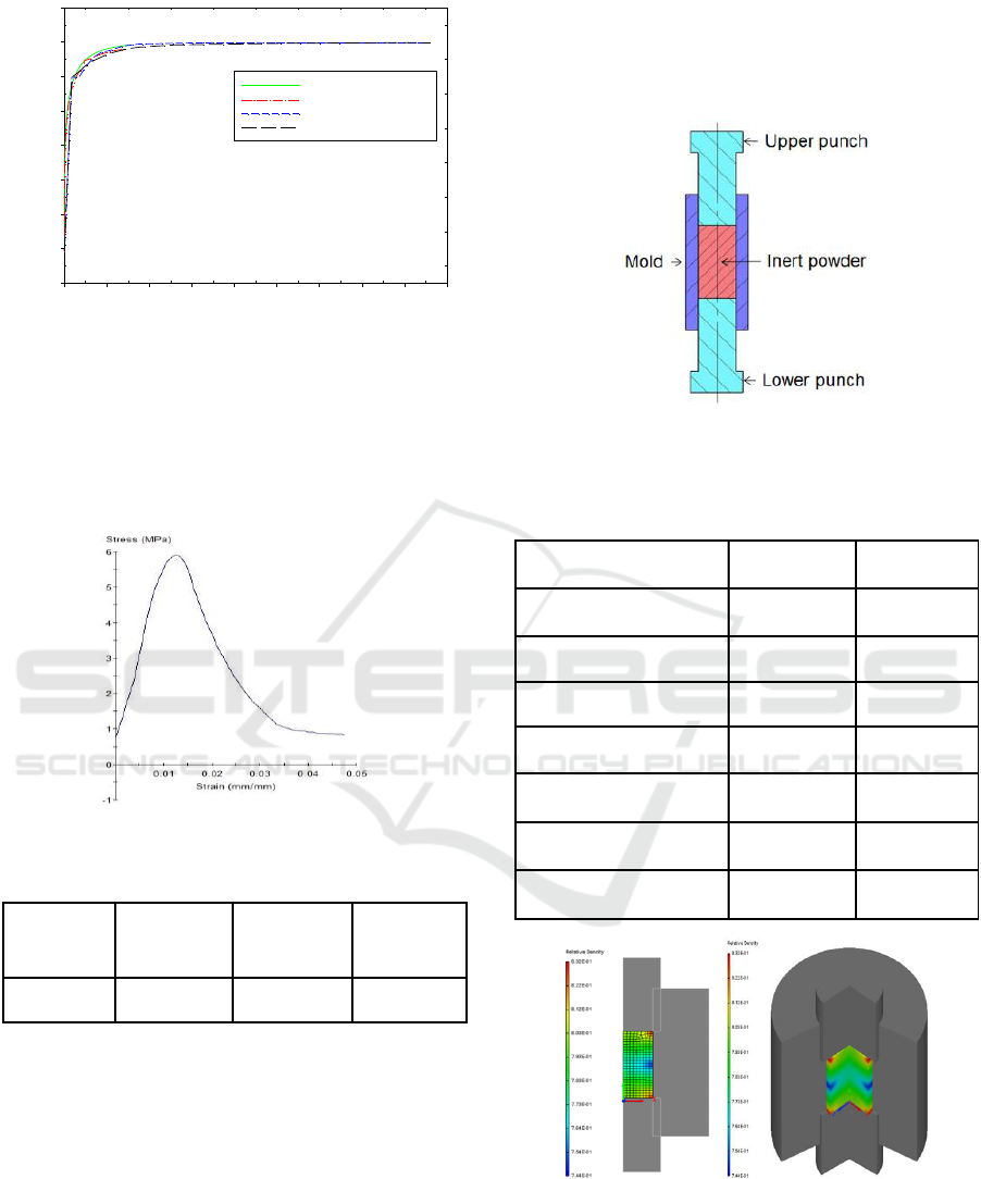
Figure 6: Variation of relative density with pressure of inert
explosive during die compression.
In this study, a uniaxial test was carried out using
a 36 mm diameter pellet. Figure 7 shows a stress-
strain curve of the inert explosive pellet. Table 2
shows mechanical properties of inert explosive pellet.
Figure 7: Stress-strain curve of the inert explosive.
Table 2: Mechanical properties.
Yield
Strength
(MPa)
Young’s
Modulus
(MPa)
Poisson’s
ratio
Shear
Modulus
(MPa)
5.87
608.97
0.272
239.37
4 RESULTS AND DISCUSSION
4.1 Double Action Pressing Model
Figure 8 shows the double action pressing model. The
analytical model uses a 36.09 mm diameter
cylindrical mold and compresses the inert explosive
powder by compressing both sides at the same time.
As a results of double action pressing for inert
explosive powder in table 3, the final shape was
almost identical when comparing the test results and
the analysis results. The difference between the initial
height of the test results and the analysis results in the
table 3 is the difference in applying the method to
reduce the mesh errors in the analysis.
Figure 8: Double action pressing model: Schematic
drawing of the mold.
Table 3: Results of inert explosive pellet.
Experiment
Simulation
Weight(g)
63.65
63.65
Initial diameter(mm)
36.09
36.09
Initial height(mm)
90.83
49.32
Initial density(g/cm
3
)
0.685
1.262
After pressing
diameter(mm)
36.04
36.09
After pressing
height(mm)
35.78
35.85
After pressing
density(g/cm
3
)
1.744
1.736
Figure 9: Double action pressing process with relative
density 0.74–0.83.
Figure 9 shows the range of relative density 0.74-
0.83 in the progress of compression, showing the
characteristic of double action pressing in which the
density of the end part of the shaped body is higher
Pressure(MPa)
0 20 40 60 80 100 120 140 160 180
Relative Density
0.3
0.4
0.5
0.6
0.7
0.8
0.9
1.0
1.1
FEM calculation(=0.1)
FEM calculation(=0.2)
Experinental Data(47g)
Experimental Data(15g)
SIMULTECH 2018 - 8th International Conference on Simulation and Modeling Methodologies, Technologies and Applications
432
and the density of the intermediate part of the shaped
body is lower.
Figure 10 shows the state over the range of
relative density 0.99 in the progress of compression
and shows that the shaped body has a uniform density
distribution as a whole.
Figure 10: Double action pressing process with relative
density 0.99 over.
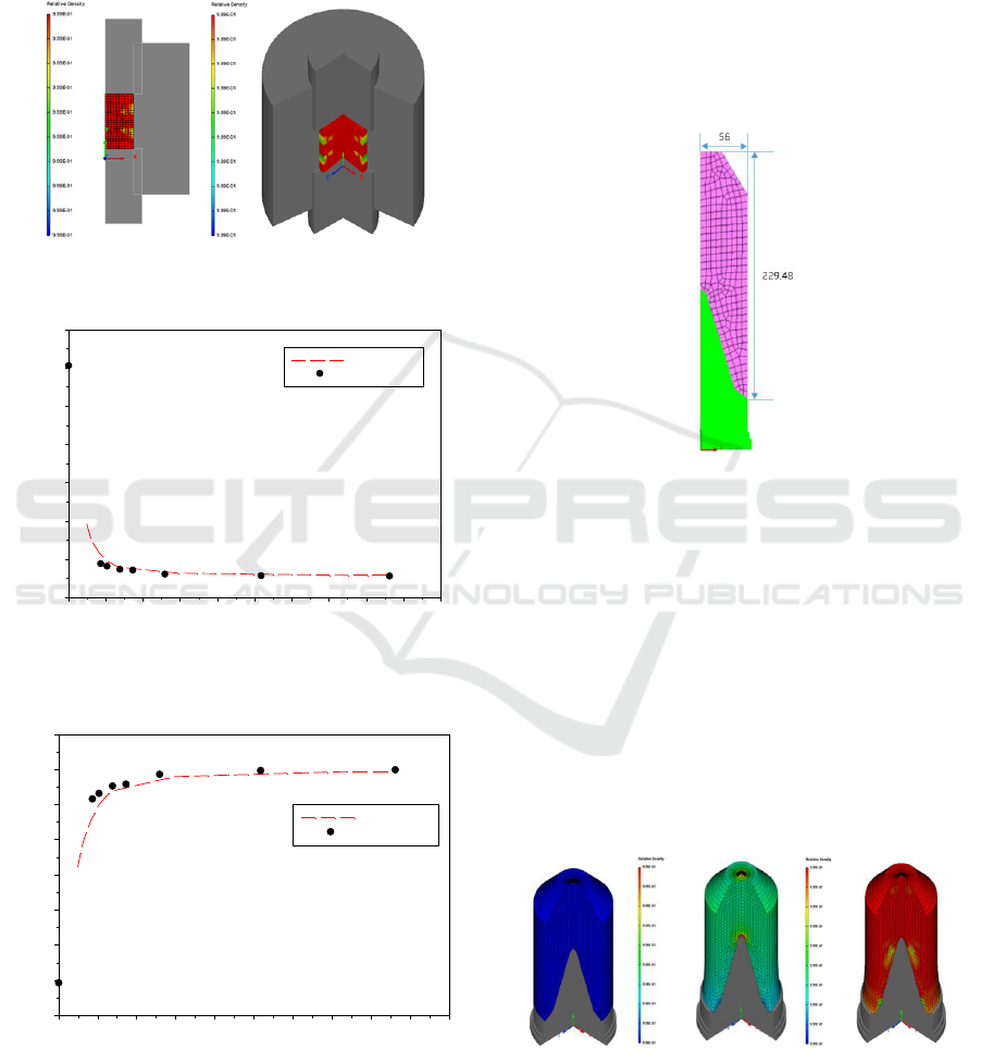
Figure 11: Variation of pellet height with pressure during
die compression of Shima-Oyane yield model.
Figure 12: Variation of relative density with pressure during
die compression of Shima-Oyane yield model.
Figure 11 shows variation of pellet height with
pressure during die compression of Shima-Oyane
yield model. It can be seen that the height difference
of the shaped body is relative large in the low pressure
range of the test process and analysis process, and the
difference is small as it goes the height pressure
range.
Figure 12 shows variation of relative density with
pressure during die compression of Shima-Oyane
yield model. As the compressive pressure increase,
the maximum relative density approaches 1.
4.2 Isostatic Pressing Model
Figure 13: Isostatic pressing modeling of Shima-Oyane
yield model.
Figure 13 shows isostatic pressing modeling of
Shima-Oyane yield model. Axisymmetric modelling
was carried out based on tests using mold of shaped
charge type with a diameter of 112 mm.
Figure 14 shows results of inert explosive
pressing simulation about pressing states with relative
densities. Figure 14(b) shows density concentration
or stress concentration at the top of the mold in the
progress of compression. When changing the shape
of a mold in a similar shape, it is necessary to consider
the design of the mold because the concentrated stress
may appear at that part.
(a) (b) (c)
Figure 14: Results of inert explosive pressing simulation :
(a) Before pressing with relative density 0.573 ; (b) Pressing
with relative density 0.98 – 0.99; (c) After pressing with
relative density 0.99 over.
Pressure(MPa)
0 20 40 60 80 100 120 140 160 180 200
Height(mm)
30
40
50
60
70
80
90
100
Simulation
Experiment
Pressure(MPa)
0 20 40 60 80 100 120 140 160 180 200
Relative Density
0.3
0.4
0.5
0.6
0.7
0.8
0.9
1.0
1.1
Simulation
Experiment
Test Evaluation and Computational Modeling Applicability for Compression Moldability of Inert Explosive
433
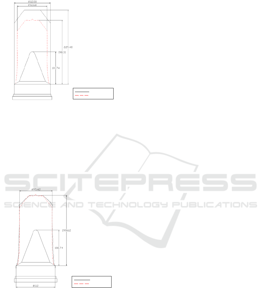
Figure 15: Result of isostatic pressing simulation with
Shima-Oyane yield model.
Figure 15 shows result of isostatic pressing
simulation with Shima-Oyane yield model. The black
line is the shape before pressing, and the red brocken
line is the shape after pressing.
Figure 16 shows comparison of inert explosive
shaped body between experiment and simulation
results. The shape of the experiment result and the
shape of the analysis result are almost the same in the
width and height of the shaped body.
Figure 16: Comparison of inert explosive shaped body
between experiment and simulation results.
5 CONCLUSIONS
The results of the double action pressing test and
analysis, in the case of the Shima-Oyane yield model
showed the results to be almost the same degree of
test results and analysis results. The results of the
isostatic pressing test and analysis, yield model for
test and analysis results showed little difference
compared to the height of the molding. Prediction of
densification behaviour for inert explosive and the
size of the final shape were obtained.
REFERENCES
Lewis RW, Jinka AGK, Gethin DT., 1993. Computer-aided
simulation of metal powder die compaction processes.
Powder Metallurgy International.
Gethin DT, Tran VD, Lewis RW, Ariffin AK., 1994. An
investigation of powder compaction process.
International Journal of Powder Metallurgy.
Kuhn HA, Downey CL., 1971. Deformation characteristics
and plasticity theory of sintered powder material.
International Journal of Powder Metallurgy.
Shima S, Oyane M., 1976. Plasticity theory for porous
metals. International Journal of Mechanical Science.
Doraivelu SM, Gelgel HL, Gunasekera JS, Malas JC,
Morgan JT., 1984. A new yield function for
compressible P/M materials. International Journal of
Mechanical Science.
Fleck NA, Huhn LT, McMeeking RM., 1992. Yielding of
metal powder bonded by isolated contacts. Journal of
the Mechanics and Physics of Solids.
Kwon YS, Lee LT, Kin KT., 1997. Analysis for cold die
compaction of stainless steel powder. ASME Journal of
Engineering Materials and Technology.
Watson TJ, Wert JA., 1993. On the development an
application of constitutive relations for metallic
powders. Metallurgical Transaction.
Before pressing
After pressing
Experiment
Simulation
SIMULTECH 2018 - 8th International Conference on Simulation and Modeling Methodologies, Technologies and Applications
434
