
TCP Congestion Control over IEEE 802.11 Wireless Lans based on
K-Means Clustering Focusing on Congestion Window Size and
Round-trip Time
Tomokazu Moriyama, Ryo Yamamoto, Satoshi Ohzahata and Toshihiko Kato
Graduate School of Informatics and Engineering, University of Electro-Communications,
1-5-1, Chofugaoka, Chofu, Tokyo 182-8585, Japan
Keywords: TCP, Congestion Control, Packet Loss Classification, IEEE 802.11 WLAN, K-Means Clustering.
Abstract: Recent IEEE 802.11 wireless LANs provide high speed data transfer using the newly introduced physical and
MAC technologies. Although packet losses over a wireless link are also decreased by the help of new MAC
technologies, some packet losses still occur randomly. Those packet losses invoke TCP congestion control,
which reduces the TCP level throughput, even if congestion does not occur at al. In order to resolve this
problem, some machine learning based approaches have been proposed, which use K-means clustering in
order to discriminate congestion triggered packet losses and wireless error triggered packet losses. However,
those proposals use only delay related parameters, but delay may increase due to non-congestion reasons, in
which case the conventional proposals fail discrimination. This paper proposes a method to classify packet
losses by the K-means clustering focusing on congestion window size and round-trip delay, and to stop
decreasing congestion window when losses are triggered by wireless errors. We develop the proposed method
as a Linux kernel module and show the performance evaluation results that the throughput increases by 40%
without increasing unnecessary packet losses.
1 INTRODUCTION
Recently, the data transfer throughput over IEEE
802.11 WLANs (Wireless LANs) has increased
significantly. The recent IEEE standards, such as
IEEE 802.11n and 11ac, introduced new PHY
(physical) and MAC (medium access control)
mechanisms (IEEE, 2016). The PHY mechanisms
including new modulation methods, MIMO
(multiple-input and multiple-output), and channel
bonding realize high data rate, and the MAC
mechanisms such as frame aggregation and block
acknowledgment (Block Ack) provide not only low
protocol overheads but also powerful data
retransmission capability.
Most of communications over IEEE 802.11
WLAN, such as web access and e-mail, use TCP
(transmission control protocol) as their transport
prptocol (IETF, 1981). One of noteworth functions in
TCP is the congestion control. When congestion
occurs at some nodes within a network, the TCP
module in a data sending node decreases its data
sending rate. However, since TCP works only at an
end node, it cannot detect a precise condition of the
node suffering from congestion. So far, dozens of
congestion control methods have been proposed
(Afanasyev et al., 2010), and most of them consider
that, if there are any packet losses, congestion occurs
somewhere in a network.
When a WLAN link exists within a path between
communicating nodes, the possibility of packet losses
will be larger than a path consisting of wired links
only, even if the recent IEEE 802.11 standards are
used. In such a case, TCP in a sending node considers
that congestion occurs and decreases the congestion
window size unnecessarily. This is a traditional issue
on TCP over wireless links and has been studied
actively (Sardar and Sara, 2006). There are many
proposals, such as modifying TCP, dividing TCP
connections, and support by lower layer protocols.
Recently, there are new trends; a machine learning
approach, i.e., the discrimination of TCP packet
losses by use of machine learning technologies.
Machine learning is a useful method which can be
applied to various fields. TCP communication is one
of the targets and several studies are proposed.
(Nunes et al., 2011) applied the Experts Framework
Moriyama, T., Yamamoto, R., Ohzahata, S. and Kato, T.
TCP Congestion Control over IEEE 802.11 Wireless Lans based on K-Means Clustering Focusing on Congestion Window Size and Round-trip Time.
DOI: 10.5220/0006836800250032
In Proceedings of the 15th International Joint Conference on e-Business and Telecommunications (ICETE 2018) - Volume 1: DCNET, ICE-B, OPTICS, SIGMAP and WINSYS, pages 25-32
ISBN: 978-989-758-319-3
Copyright © 2018 by SCITEPRESS – Science and Technology Publications, Lda. All rights reserved
25
technique to RTT (round-trip time) estimation.
(Mirza et al., 2010) proposed how to predict TCP
throughput using the SVR (support vector regression)
technique. (Chung et al., 2017) applied the random
decision forests to an MPTCP scheduler that selects a
subflow to send data segments by considering
performance metrics such as the MAC data rate,
signal strength, and network congestion.
As for the packet loss discrimination,
(Sooriyabandara et al., 2010) and (Morifuji and
Hiraki, 2013) proposed approaches that a data sender
infers the cause of packet losses by use of the K-
means clustering method (Hand et al., 2001). (Deng
and Cai, 2009) focused on MANET (mobile ad hoc
network) and adopted SVM (support vector machine)
to allow a data receiver to differentiate packet losses.
This paper improves the work done by
(Sooriyabandara et al., 2010) and (Morifuji and
Hiraki, 2013). These two papers focused only delay
related parameters such as one way delay and RTT.
In this paper, we use congestion window size (cwnd)
as well as RTT, and classify two types of packet
losses, i.e. congestion losses and wireless losses, by
use of the K-means clustering. Moreover, we propose
a congestion control method that skips the cwnd
decreasing when a packet loss is classified as a
wireless loss. The rest of this paper is organized as
follows. Section 2 gives some background
information including the overview of IEEE 802.11
WLAN and the TCP congestion control, some
previous comments on packet losses over WLAN, the
overview of K-means clustering, and some related
work. Section 3 describes the proposed method and
Section 4 gives the performance evaluation results. In
the end, Section 5 concludes this paper.
2 BACKGROUNDS
2.1 IEEE 802.11 WLAN and TCP
Congestion Control
As described above, the recent IEEE 802.11
standards, 11n and 11ac, introduce new MAC
mechanisms for high speed and efficient data frame
transmission; the frame aggregation and Block Ack.
The frame aggregation allows multiple data frames
(called MAC protocol data units: MPDUs) to be
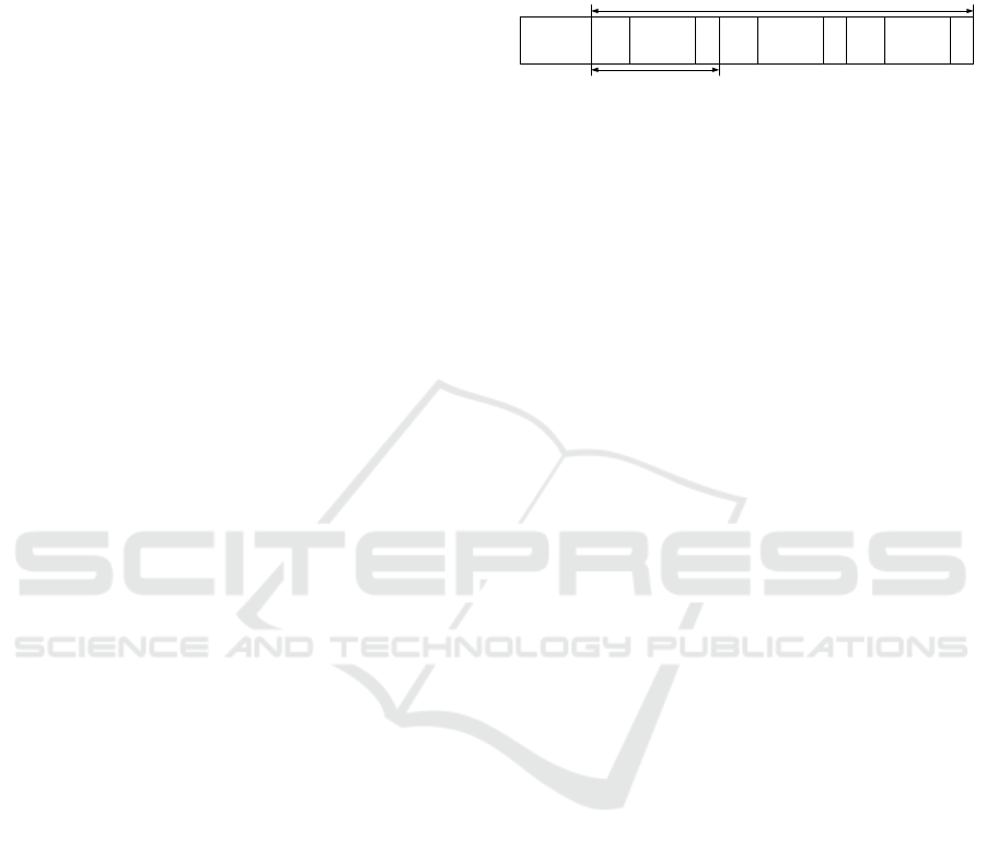
aggregated and sent together. The whole transmitted
frame is called A-MPDU (Aggregation MPDU), and
is a collection of A-MPDU subframes, each of which
includes an MPDU delimiter, an MPDU body, and a
padding, as shown in Figure 1. An MPDU delimiter
contains the MPDU length, a cyclic redundancy
check (CRC) to detect bit errors within the delimiter
itself. A padding consists of 0 through 3 bytes, which
make the length of an A-MPDU subframe a multiple
of 4 bytes.
MPDU
delimiter
WLAN
data frame
(MPDU)
PAD
PLCP preamble,
PLCP header
MPDU
delimiter
WLAN
data frame
(MPDU)
PAD
MPDU
delimiter
WLAN
data frame
(MPDU)
PAD
A-MPDU
A-MPDU subframe
PLCP: physical layer convergence protocol,
MPDU: MAC protocol data unit,
A-MPDU: Aggregation MPDU, PAD: padding
Figure 1: Structure of A-MPDU.
The IEEE 802.11n and 11ac standards adopt an
acknowledgment scheme called high throughput
(HT)-immediate Block Ack. When a receiver
receives an A-MPDU, it replies a Block Ack frame
which contains a Block Ack Bitmap parameter
indicating whether it correctly receives a MPDU with
a specific sequence number. The Bitmap indicates
receipt or non-receipt of 64 MPDUs. The data sender
retransmits non-received MPDUs according to the
Bitmap. When a Block Ack frame itself is lost, the
whole A-MPDU is retransmitted by timeout.
TCP uses cwnd in addition with an advertised
window size (awnd) which a data receiver reports in
a TCP header. A data sender transmits data segments
according to the smaller of cwnd and awnd. TCP
Reno / NewReno (Henderson et al., 2012) is a
traditional congestion control method, which is still
used widely. cwnd is controlled in an AIMD (additive
increase and multiplicative decrease) mechanism.
When receiving an ACK segment reporting the
receipt of new data segments (a new ACK), cwnd is
increased by 1/cwnd (segments), and when any data
segments are retransmitted in response to three
duplicate ACKs (fast retransmit), cwnd is halved.
CUBIC (Ha et al, 2008) is a relatively new congestion
control method, which is a default in the Linux
operating system. cwnd increases in a cubic function
of time from the last fast retransmit. At the fast
retransmit, cwnd decreases to 70% (80% in the
original version) of the cwnd value just before the
retransmission.
In those methods, a data sender detects congestion
by a packet loss (retransmission). In TCP Vegas
(Brakmo and Peterson, 1995), on the other hand, a
data sender monitors RTT and estimates the queue
length at a bottleneck node. If the estimated queue
length is smaller than a threshold, a sender increases
cwnd by one segment during one RTT timeframe. If
the queue length is larger than another threshold, a
sender decreases cwnd by one segment during one
RTT timeframe. Otherwise, a sender keeps cwnd as it
is. That is, TCP Vegas is a mechanism based on the
delay.
DCNET 2018 - International Conference on Data Communication Networking
26
There are some congestion control methods based
on packet losses and delay. TCP Veno (Fu and Liew,
2003) and Compound TCP (Tan et al., 2006) are
examples. They decrease cwnd at a packet loss, and
control the cwnd increase and decrease depending on
the congestion status estimated by RTT. If network is
congested, they work like TCP Reno, and if not
congested, they increase cwnd more aggressively.
2.2 Packet Losses over 802.11 WLAN
As mentioned in the previous subsection, the recent
IEEE 802.11 WLANs provide highly reliable data
transfer by use of the HT-immediate Block Ack
mechanism, compared with the older IEEE standards
that used the one-to-one mapping between data and
Ack frames. However, a few packet losses occur
resulting from the retry-out in the MAC level
retransmission.
(a) Network configuration
(b) Packet loss rate
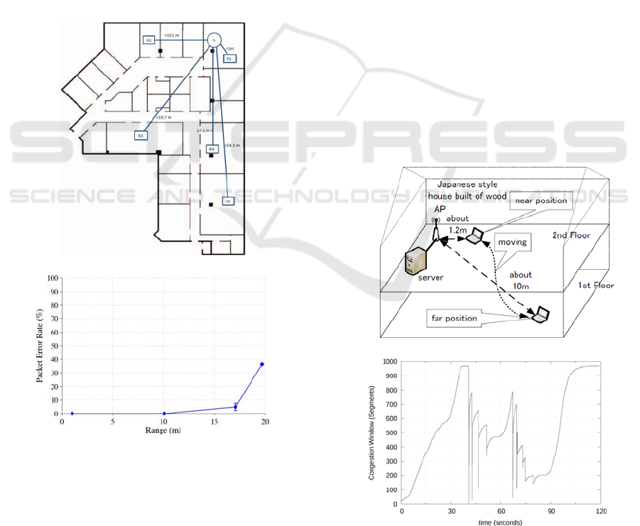
Figure 2: UDP data transfer over 802.11ac WLAN. (Dianu
et al., 2014).
Figure 2 shows a result of the performance
evaluation of 802.11ac LAN in an indoor
environment given in (Dianu et al., 2014). As shown
in Figure 2 (a), a sender is located at position S and a
receiver is at one of positions R1 through R5. A
sender generates 30 second UDP data traffic using
iperf. Figure 2 (b) shows the result of packet error
ratio in response to the distance between the sender
and the receiver. In the case that the distance is 10.1
m (position R2), there are some packet losses
although the rate is under 1%, which means that
wireless losses happen in an IEEE 802.11ac WLAN.
Figure 3 shows another example of performance
evaluation of 802.11n WLAN, which was conducted
for evaluating Bufferbloat problem (Nomoto et al,
2014). As shown in Figure 3 (a), a station starts
sending data to the server at the far most position for
30 seconds, moves to the nearest position, and stays
there for 30 seconds. Then, it moves to the far position
again. At the far most position, the station uses 6.5 or
13 Mbps data rate, and uses rate close to 300 Mbps at
the nearest position. Figure 3 (b) shows the time
variation of cwnd measured at the station. From time
0 to 40 seconds, and 80 to 120 seconds, that is, while
the station is moving or in the far most position, cwnd
keeps increasing. This means there are no packet
losses. On the other hand, while the station stays at
the nearest position, there are ten drops in the cwnd
graph, each of which corresponds to a packet loss.
Since there are no bottlenecks in the data transfer
from the station to the server, these losses are
considered as wireless losses. This result shows
wireless losses happen in an 802.11n WLAN.
(a) Network configuration
(b) cwnd vs. time
Figure 3: TCP data transfer over 802.11n WLAN. (Nomoto
et al., 2014).
TCP Congestion Control over IEEE 802.11 Wireless Lans based on K-Means Clustering Focusing on Congestion Window Size and
Round-trip Time
27
2.3 K-Means Clustering
In this subsection, we explain the K-means clustering
that we use to classify TCP packet losses. The K-
means algorithm is a type of unsupervised learning.
The goal of this algorithm is to categorize unlabelled
data into K groups. Specifically, it minimizes an
objective function ∅;
∅
‖
̅
‖
.
∈
(1)
Here, is a set of data,
is a cluster, i.e. a disjoint
subset such that
⋃
the set of data, and ̅
is
the cluster center of
in a Euclidean distance sense.
The algorithm is summarized in the following way.
1. Assign data into K clusters randomly.
2. Calculate the center of each cluster by
̅
1
|
|
∈
.
(2)
3. Reassign all data into a new cluster in a way that
a Euclidean distance
‖
̅
‖
is the minimum for
̅
.
4. Repeat steps 2 and 3 until there are no changes in
clusters or the maximum repeat count is exceeded.
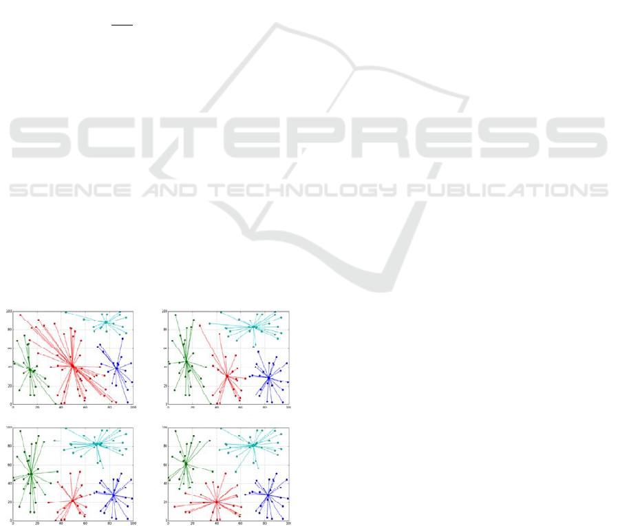
Figure 4 shows an example of the K-means clustering.
A hundred points are selected randomly in the field of
(0, 0) through (100, 100). The above algorithm is
applied once, twice, three times and eight times. As
the repeat count increases, the total of distance
between individual points and the corresponding
cluster center becomes small.
2.4 Related Work
repeat count = 1 repeat count = 2
repeat count = 3 repeat count = 8
Figure 4: Example of clustering by K-means clustering.
In order to classify TCP packet losses as a congestion
loss and a wireless loss, (Sooriyabandara et al., 2010)
uses two delay based parameters, one way delay
(OWD) and inter-arrival time (IAT) of ACK
segments, as data for the K-means clustering. A TCP
data sender keeps a record of OWD and IAT for the
three most recent ACKs, and if there is a packet loss,
that is, a duplicate ACK is received, a sender
classifies this loss event into two groups. A sender
determines this loss as a congestion loss or a wireless
loss depending on the mean OWD of last three ACKs.
If it belongs to a congestion loss category, then a
sender follows the standard TCP back-off procedure,
and if not, cwnd is not decreased. (Sooriyabandara et
al., 2010) shows some performance results by use of
the network simulator ns-2 successfully, but OWD is
difficult to measure in an actual network.
(Morifuji and Hiraki, 2013), on the other hand,
uses RTT for discriminating packet losses. It records
RTT for packets and discriminates the type of losses
based on RTT records. Only if a packet is classified
into the congestion loss, a data sender decreases cwnd.
Through a simulation based performance evaluation,
they confirmed that this method improves TCP
throughput.
3 PROPOSAL
Basically, both of the related work discussed in the
previous section use a delay based parameter for the
K-means clustering. That is, if congestion occurs,
OWD or RTT will increase, and so a packet loss with
a large delay may be a congestion loss in a high
probability. On the other hand, a packet loss with a
small delay might be a wireless loss. However, over
an IEEE 802.11 WLAN link, delay may change for
other reasons. For example, IEEE 802.11 WLAN
uses multiple data rates and the dynamic rate
switching, and when a station is located far from an
access point and the data rate is low, the transmission
delay will increase. Besides, in our previous paper
(Moriyama et al., 2017), we showed that, if there is
an unbalanced traffic load when the multi-user
MIMO is used together with the frame aggregation in
802.11ac, transmission delay may increase. Therefore,
it is possible that the K-means clustering using only
delay based parameters may lead to wrong
categorization.
In this paper, we focus on cwnd itself together
with RTT to apply the K-means clustering, because it
is considered that the probability of congestion
increases when the value of cwnd is large. In the
proposed method, cwnd is decreased as in the original
DCNET 2018 - International Conference on Data Communication Networking
28
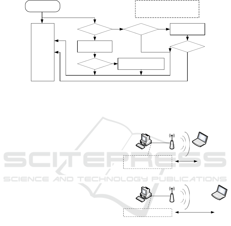
Figure 5: Flow chart of proposed method.
TCP if the data retransmission is classified as a
congestion loss, but if classified as a wireless loss, a
data sender does not decrease cwnd.
Figure 5 shows detailed algorithm flow of the
proposed method. For new ACKs, a sender records
(cwnd, RTT) pair, and the average of three of these
pairs is maintained as y[j]. If a sender receives a
duplicate ACK segment, then it applies the newest
y[j] to the K-means clustering. If y[j] is categorized as
a wireless loss, then the cwnd decreasing is stopped
in the original ACK processing. Otherwise, the
original TCP congestion control is performed.
4 PERFORMANCE EVALUATION
4.1 Experiment Conditions
In order to evaluate the performance of the proposed
method, we implemented it over the Linux operating
system (Ubuntu 16.04LTS). We also implemented
the method described in (Morifuji and Hiraki, 2013),
which uses only RTT for the K-means clustering (we
call this method conventional method). The
maximum number of data used in the K-means
clustering is 10,000 and the maximum repeat count is
set to 50,000.
Figure 6 shows the experimental configuration. A
server, a data sender, is connected to Gigabit Ethernet,
which is connected with an IEEE 802.11ac access
point at the other end. There is one station, a data
receiver, in this WLAN.
We used two scenarios in the experiment. In
scenario 1, 30 msec delay and random packet errors
are inserted at the output port in the server. The
distance between the access point and the station is
about 1 m. The inserted packet loss rate is 0.03%,
0.3%, or 3%. In scenario 2, on the other hand, only 30
msec delay is inserted at the server, and the distance
between the access point and the station is about 7 m.
Server
(sender)
Access point
802.11ac
Station (receiver)
Ethernet
1Gbps
insert 30 msec delay and
random packet errors
〜 1m
(a) Scenario 1
Server
(sender)
Access point
802.11ac
Station (receiver)
Ethernet
1Gbps
insert 30 msec delay
〜 7m
(
b
)
Scenario 2
Figure 6: Experimental configuration.
In the experiment, the communication duration is
90 sec. We compare the performance of TCP Reno,
the conventional method (Morifuji and Hiraki, 2013),
and the proposed method. For each method, we
executed twenty-five experiment runs for measuring
throughput and number of duplicate ACKs.
4.2 Evaluation Results in Scenario 1
Figure 7 shows the average throughput measured in
scenario 1. The graph shows the results of Reno, the
conventional method (Conv. Method in the figure),
and the proposed method (Prop. Method). Along with
the increase of packet error rate inserted artificially,
Receiving ACK
segment
original
ACK
processing
duplicate ACK ?
i++;
x[i] = (cwnd, RTT)
j>3
j++;
y[j]=(x[i]+x[i-1]+x[i-2])/3
j>10
apply
K
-means to
y
y[j] is congestion
no action
N
YY
Y
N
N
N
Y
stop decreasing cwnd
x[i]: recorded data,
j: number of data
y[j]: average of recent three data
TCP Congestion Control over IEEE 802.11 Wireless Lans based on K-Means Clustering Focusing on Congestion Window Size and
Round-trip Time
29
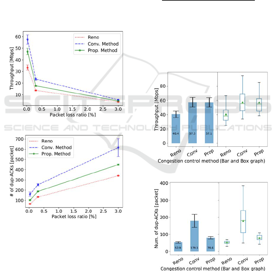
the throughput decreases in all the cases. The
throughput is the lowest in the original TCP Reno.
The two K-means clustering methods improve the
throughput. The conventional method provides better
throughput than the proposed method. Figure 8 shows
the number of duplicate ACKs during one
experimental run. This has a similar trend with the
average throughput. TCP Reno is the smallest and the
conventional method is the largest.
Those results mean that the conventional method
is the most aggressive, that is, the conventional
method handles large number of packet losses as
wireless losses and does not decrease cwnd. As a
result, the average throughput becomes high, and
consequently the number of packets sent increases,
which increases the packet losses again.
Figure 7: Throughput in scenario 1.
Figure 8: Number of duplicate ACKs in scenario 1.
4.3 Evaluation Results in Scenario 2
Figure 9 shows the average throughput in scenario 2.
In this scenario, both the conventional method and the
proposed method realize 40% improvement
compared with the original TCP Reno. On the other
hand, as shown in Figure 10, the number of duplicate
ACKs is 3.4 times in the conventional method and 1.5
times in the proposed method, compared with Reno.
This means that, although the throughput
improvement is similar for the conventional method
and the proposed method, the conventional method
induces the increase of packet losses.
The number of transmitted packets increases as
the throughput increases. Along that, the number of
duplicate ACKs also increases. In order to evaluate
the number of duplicate ACKs independently of the
amount of transmitted packets, we define the
congestion index α by the following equation;
α
.
(3)
Figure 11 shows the average of congestion index.
From this graph, the proposed method does not
increase the congestion index from the original Reno,
while the congestion index of the conventional
method increases, as twice as the original Reno. This
result means that the proposed method realizes high
performance without increasing unnecessary packet
losses, that is, without deteriorating congestion.
Figure 9: Throughput in scenario 2.
Figure 10: Number of duplicate ACKs in scenario 2.
DCNET 2018 - International Conference on Data Communication Networking
30
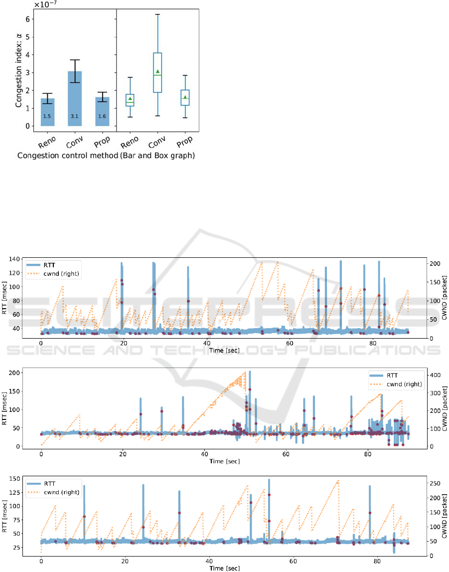
Figure 11: Ratio of duplicate ACKs for total segments in
scenario 2.
In the end of this subsection, we show a detailed
result for individual experimental run for 90 seconds.
Figure 12 shows the time variation of RTT and cwnd
for TCP Reno, the conventional method, and the
proposed method. Red dots in the graph of RTT show
three duplicate ACKs triggering fast retransmit. In the
case of TCP Reno, every three duplicate ACK
decreases cwnd as indicated in Figure 12 (a). Some of
these decreases are wireless loss driven events. In the
conventional method given in Figure 12 (b), cwnd
does not decrease when RTT is small, and so, there
are many chances that cwnd take larger value than
TCP Reno. But, sometimes cwnd does not decrease
even if the value is large (see around 50 seconds and
80 seconds). It is considered that these situations
deteriorate congestion. On the contrary, in the
proposed method given in Figure 12 (c), cwnd does
not decrease while RTT is small and cwnd decreases
when the cwnd value itself is large.
5 CONCLUSIONS
In this paper, we proposed a method to classify TCP
packet losses over IEEE 802.11 WLAN into conges-
(a) TCP Reno
(b) Conventional method
(c) Proposed method
Figure 12: Time variation of RTT and cwnd in scenario 2.
TCP Congestion Control over IEEE 802.11 Wireless Lans based on K-Means Clustering Focusing on Congestion Window Size and
Round-trip Time
31

congestion losses and wireless losses by the K-means
clustering focusing on both congestion window size
and round-trip time. The proposed method modifies
the TCP congestion control such that if packet losses
are categorized as wireless losses, the congestion
window size does not decrease. We implemented the
proposed method within the Linux operating system
and conducted the performance evaluation using real
WLAN network. The results showed that the
proposed method provides 40% higher throughput
than TCP Reno and that it does not increase the ratio
of duplicate ACKs to the total packets, which the
conventional method focusing only on RTT suffered
from.
REFERENCES
IEEE Std 802.11-2016, 2016. IEEE Standard for
Information technology – Part11: Wireless LAN
medium Access Control (MAC) and Physical Layer
(PHY) Specifications.
IETF, 1981. Transmission Control Protocol, DARPA
Internet Protocol Specification. RFC 793.
Afanasyev, A., Tilley, N., Reiher, P., Kleinrock, L., 2010.
Host-to-Host Congestion Control for TCP. IEEE
Commun. Surv. Tut., Vol. 12, No. 3, pp. 304-342.
Sardar, B., Saha, D., 2006. A Survey of TCP Hnhancements
for Last-hop Wireless Networks. IEEE Commun. Surv.
Tut., Vol. 8, No. 3, pp. 20-34.
Nunes, B, et al., 2011. A Machine Learning Approach to
End-to-End RTT Estimation and its Application to TCP.
In Proc. 20th Int. Conf. on Computer Communications
and Networks (ICCCN), pp. 1-6.
Mirza, M., Sommers, J., Barford, P., Zhu, X., 2010. A
Machine Learning Approach to TCP Throughput
Prediction. IEEE/ACM Trans. Networking, Vol. 18, No.
4, pp. 1026-1039.
Chung, J., Han, D., Kim, J., Kim, C., 2017. Machine
Learning based Path Management for Mobile Devices
over MPTCP. In Proc. 2017 IEEE Int. Conf. Big Data
and Smart Computing (BigComp), pp. 206-209.
Sooriyabandara, M., et al., 2010. Experience with
Discriminating TCP loss using K-Means Clustering. In
Proc. 2010 Int. Conf. Information and Communication
Technology Convergence (ICTC), pp. 352-357.
Morifuji, F., Hiraki, K., 2013. Loss Classification
Algorithm for Enhancing TCP Data Transmission (in
Japanese). In IEICE Technical Report CPSY2013-19.
Hand, D., Mannila, H., Smyth, P., 2001. Principles of Data
Mining. MIT Press.
Deng, Q., Cai, A., 2009. SVM-based loss differentiation
mechanism in Mobile Ad hoc Networks. In Proc. 2009
Global Mobile Congress, pp. 1-4.
Henderson, T., Floyd, S., Gurtov., A., Nishda, Y., 2012.
The NewReno Modification to TCP’s Fast Recovery
Algorithm. IETF RFC 6582.
Ha, S, Rhee, I., Xu. L., 2008. CUBIC: a new TCP-friendly
high-speed TCP variant. ACM SIGOPS Op. Syst. Rev.,
Vol. 42, Issue 5, pp. 64-74.
Brakmo, L., Peterson, L., 1995. TCP Vegas: End to End
Congestion Avoidance on a Global Internet. IEEE J. Sel.
Areas Commun., Vol. 13, No. 8. pp. 1465-1480.
Fu, C., Liew, S., 2003. TCP Veno: TCP Enhancement for
Transmission Over Wireless Access Networks. IEEE J.
Sel. Areas Commun., Vol. 21, No. 2, pp. 216-228.
Tan, K., Song, J., Zhang, Q., Sridharan, M., 2006. A
Compound TCP Approach for High-speed and Long
Distance Networks. In Proc. IEEE INFOCOM 2006, pp.
1-12.
Dianu, M., Riihijarvi, J., Petrova, M., 2014. Measurement-
Based Study of the Performance of IEEE 802.11ac in
an Indoor Environment. In Proc. IEEE ICC 2014 –
Wireless Communications Symposium, pp. 5771-5776.
Nomoto, M., Kato, T., Wu, C, Ohzahata, S., 2014.
Resolving Bufferbloat Problem in 802.11n WLAN by
Weakening M\ac Loss Recovery for TCP Stream. In
Proc. IASTED Int. Conf. Parallel and Distributed
Computing and Networks (PDCN 2014), pp. 293-300.
Moriyama, T., Yamamoto, R., Ohzahata, S., Kato, T., 2017.
Frame Aggregation Size Determination for IEEE
802.11ac WLAN Considering Channel Utilization and
Transfer Delay. In Proc. WINSYS 2017, pp. 89-94.
DCNET 2018 - International Conference on Data Communication Networking
32
