
Adaptive Channel Allocation Algorithm Suitable for WDM
Networks: An Analytical Study
Peristera A. Baziana
School of Electrical and Computer Engineering, National Technical University of Athens, Athens, Greece
Keywords: Performance Evaluation, Wavelength Assignment, Wavelength Division Multiplexing.
Abstract: In this paper, we adopt a network configuration and an efficient synchronous transmission access protocol
suitable for WDM networks of passive star topology. Especially, a single control channel is assumed for the
control information exchange, prior to the data packets transmission, in order to properly coordinate the data
packets communication. According to the proposed WDMA scheme, a data channel is assigned at each
station that attempts data packet transmission, totally avoiding the collisions over the data multi-channel
system. The system performance measures are analytically derived based on a Markovian model. Numerical
results are studied for diverse numbers of data channels.
1 INTRODUCTION
Modern trends in Wavelength Division Multiplexing
(WDM) (Zheng and Mouftah, 2004) networks are
dealing with the idea of exploring diverse network
resources allocation methods in order to improve the
performance. Many different topologies and network
configurations have been proposed, not only in
literature but also in implemented projects.
Especially, the use of a single control channel for
the control information exchange, prior to the data
packets transmission, has been extensively studied
by Pountourakis (1998). The provided benefits, as
compared with the case where there are no pre-
transmission coordination access schemes, are based
on the fact that the packets competition is restricted
during the control transmission phase, while the
packet loss can be totally avoided during the data
transmission phase. In this way, the network is
capable of reaching high performance. Also,
Pountourakis et al., (2006) and Baziana (2014 and
2016) adopt the Multi-Channel Control Architecture
(MCA) where there are multiple parallel control
channels for the control information exchange, in
order to reduce the control processing time at the
station electronics (Humblet et al., 1993).
It is obvious that the WDM networks
performance is restricted by the packets loss due to
the concurrent transmission of more than one
packets over the same channel. This phenomenon is
referred as WDM channels collisions. It causes
system throughput reduction and delay increase.
In this paper, we explore the idea of adopting a
wavelength assignment algorithm in order to
improve the system performance. We assume a
WDM passive star Local Area Network (LAN) that
uses a single control channel in order to coordinate
the data packets transmission and to reduce the data
packets collisions over the data channels. A pre-
transmission coordination scheme is considered in
order for the stations to gain collisions-free access
over the data channel multi-channel system. For this
reason, we assume the division of the set of the data
channels into two equal sets. At each station, a
wavelength assignment algorithm over the two data
channels sets is implied in a decentralized way. A
synchronous transmission WDM Access (WDMA)
protocol is proposed that takes under consideration
the control channels collisions and the data packets
loss due to the wavelength assignment competition.
The proposed protocol provides significant
performance improvement, as compared to the
network case that uses a single data channel set.
The performance measures evaluation is based
on the study of the closed mathematical formulas
provided by a Markovian model. The proposed
protocol performance is extensively studied for
several, numbers of data channels.
The paper is organized as follows. Section 2
presents the network model and the assumptions.
The analysis is provided in Section 3. Numerical
Baziana, P.
Adaptive Channel Allocation Algorithm Suitable for WDM Networks: An Analytical Study.
DOI: 10.5220/0006848402350240
In Proceedings of the 15th International Joint Conference on e-Business and Telecommunications (ICETE 2018) - Volume 1: DCNET, ICE-B, OPTICS, SIGMAP and WINSYS, pages 235-240
ISBN: 978-989-758-319-3
Copyright © 2018 by SCITEPRESS – Science and Technology Publications, Lda. All rights reserved
235

results are studied in Section 4. The conclusion is
outlined in Section 5. The Appendix gives the proof
of the closed formula for the probabilistic evaluation
of the wavelength assignment access scheme over
the data channels system.
2 NETWORK MODEL AND
ASSUMPTIONS
We assume a LAN that uses a passive star coupler to
interconnect a finite number M of stations, as Fig. 1
shows. The bandwidth is divided into (N+1) WDM
channels, each using in a different wavelength {λ
0
,
λ
1
,.... λ
Ν
}, where N is an even integer. The channel
λ
0
is called control channel, while the channels {λ
1
,
λ
2
,.... λ
N
} are called data channels. The set of data
channels is divided into two sets with equal number
of wavelengths. Thus, the first data channel set A
1
consists of the wavelengths {λ
1
, λ
2
,.... λ
Ν/2
}, while
the second data channel set A
2
consists of the
wavelengths {λ
1+N/2
, λ
2+N/2
,.... λ
Ν
}. In this way, the
data channel λ
x
, where: x ϵ {1, 2,.... Ν/2} from the
set A
1
has an one to one correspondence to the data
channel λ
y
, where: y ϵ {Ν/2+1, Ν/2+2,....N} from
the set A
2
. Each station is equipped with a tunable
transmitter and a tunable receiver that can be tuned
to any channel. For the tunable transceivers, we
assume large tuning range.
The control packet transmission time is defined
as time unit and is called mini-slot. The data packet
transmission time is L time units and is called data
slot. We denote as t
t
and t
r
the tunable transmitter
and receiver tuning time respectively. We define the
time interval T in time units as: T=max{t
t
, t
r
}. The
control packet consists of the source and the
destination address and the data channel λ
k
, where: k
ϵ {1, 2,.... Ν/2} that has been chosen from the set A
1
for the data transmission. The normalized round trip
propagation delay between any pair of stations is
assumed to be R time units.
All channels use the same time reference which
is called cycle. The cycle is defined as the time
interval that includes: T time units for the
transceivers tuning, plus v time units for the control
packets transmissions, plus the normalized
propagation delay R, plus T time units for the
transceivers tuning, plus the normalized data packet
transmission time L, as Fig. 2 shows. The cycle time
duration C is:
Figure 1: Network model.
Figure 2: Cycle duration.
C=T+v+R+T+L time units (1)
Time axis is divided into contiguous cycles. Each
cycle consists of the tuning phase for the control
packets communication, the control phase, the
propagation delay, the tuning phase for the data
communication, and the data phase, as Fig. 2 shows.
The control phase consists of v time units, while the
data phase lasts for L time units. At the beginning of
the data phase, each station is able to transmit with it
tunable transmitter at a data channel λ
T
, while
simultaneously receive from a data channel λ
R
,
where λ
T
, λ
R
ϵ {λ
1
, λ
2
,.... λ
N
}.
At the beginning of a cycle, each station tunes its
tunable receiver to the control channel λ
0
to monitor
the control packets transmissions from all stations
during the control phase. Also, if it has to send a
data packet to another station, it tunes its tunable
transmitter to the control channel λ
0
. The tunable
transceivers tuning is performed during the first T
mini-slots of the cycle. After the end of this time
period, the station chooses randomly one of the data
channels from the set A
1
for the data packet
transmission, let’s say data channel λ
i
ϵ {λ
1
,.... λ
Ν/2
}.
Also, it chooses randomly one of the control mini-
slots for the control packet transmission, let’s say the
control mini-slot j ϵ {1, 2,.... v}. Then, it informs the
other stations about the λ
i
selection, by transmitting
a control packet during the j-th control mini-slot
with its tunable transmitter. The control packets
from all stations compete according to the Slotted
Aloha scheme. The station continuously monitors
the control channel with its tunable receiver during
the control phase and the propagation delay time
OPTICS 2018 - International Conference on Optical Communication Systems
236

period. After the end of this period, the station is
aware of the data channel claims for transmission of
all stations, grace to the broadcast nature of the
control channel. We can say that the successfully
transmitted control packets are uniformly distributed
to the N/2 data channels with equal and constant
probability 2/N. So, if one or more other stations
have selected the same j-th control mini-slot for
transmission, the corresponding control packets have
collided during the j-th control mini-slot and are all
aborted. On the contrary if the control packet has
been successfully transmitted over the j-th control
mini-slot, the station has to check the data channel
field of the other successfully transmitted control
packets. Thus, if exactly one more station has
chosen the same data channel λ
i
for transmission and
its control packet transmission was successful, then
the i-th data channel from the set A1 is assigned to
the first station for transmission, while the i-th data
channel from the set A
2
is assigned to the second
station for transmission, i.e. the λ
i
and λ
i+N/2
data
channels respectively. Also, if more than one
stations have chosen the same data channel λ
i
for
transmission and their control packets transmissions
were successful, then an arbitration rule for the data
channels assignment may be considered, such as
priority. In this case, only two of these stations gain
access to the data channels λ
i
and λ
i+N/2
for
transmission during the cycle data phase, while the
other data packets transmissions are cancelled. The
stations who gain the access over the data channels
start tuning their tunable transmitter to the assigned
channels for the transmission. The tuning period
lasts for T time units. The data packet transmission
will start R+T time units after the end of the control
phase, as Fig. 2 shows. At the same time instant, the
data packets reception will also start by the
destination stations.
Packets are generated independently at each
station following a geometric distribution, i.e. a
packet is generated at each cycle with birth
probability p. A backlogged station retransmits the
unsuccessfully transmitted packet following a
geometric distribution with probability p
1
. We
assume that each station is equipped with a
transmitter buffer with capacity of one data packet.
If the buffer is empty the station is said to be free,
otherwise it is backlogged. If a station is backlogged
and generates a new packet, the packet is lost. Free
stations that unsuccessfully transmit on the control
channel or in case of loss at the channel assignment
competition during a cycle, are getting backlogged
in the next cycle. A backlogged station is getting
free at the next cycle, if it manages to retransmit
without collision over a control channel and its data
packet retransmission is not aborted due to the
channel assignment competition.
3 ANALYSIS
The examined system performance can be described
by a discrete time Markov chain. We denote the
state of the system by Xt, t=1,2… where Xt=0,1…M
is the number of backlogged stations at the
beginning of a cycle. Let:
Hc =The number of new control packets arrivals
at the beginning of a cycle, c=0,1,2,…
Ac = The number of successfully transmitted
data packets over the N data channels at the end of a
cycle, c=0,1,2…
S(x)=The number of successfully transmitted
control packets during the v control mini-slots,
conditional that x (re)transmissions occurred during
a cycle, c=0,1,2,….
The probability of y successes over the v control
mini-slots from x (re)transmissions during a cycle is
given by Szpankowski (1983):
)x,vmin(
yj
jxj
x
y
)!jx()!jv()!yj(
)jv()1(
!yv
!x!v)1(
]y)x(SPr[
(2)
and 0 ≤ y ≤ min(v,x) and x-y ≠ 1
Also, let:
A(y)=The number of successfully transmitted
data packets over the N data channels, conditional
that y successful (re)transmissions occurred during
the v control mini-slots, during a cycle.
The probability
]z)y(APr[ of z successfully
transmitted data packets over the N data channels,
conditional that y successful (re)transmissions
occurred during the v control mini-slots, during a
cycle, is given by:
)2y AND zy(:if ),z,y(prob
2)y AND zy(:if ,1
)2z AND zy( OR )zy(:if ,0
]z)y(APr[
(3)
where:
i,i2zyS ! i
i
iz
! i2z
i2z
y
iz
2
N
N
2
)z,y(prob
2
2
z
ui
y
(4)
and:
Adaptive Channel Allocation Algorithm Suitable for WDM Networks: An Analytical Study
237

zy:if ,0
zy:if ,1
u
(5)
The proof of (4) is given in the Appendix.
We define the function Φv(x,y,z) as the product
of the probability of y successes from x
(re)transmissions during the v control mini-slots,
times the probability of z successfully transmitted
data packets over the N data channels during a cycle,
i.e.:
]z)y(APr[]y)x(SPr[)z,y,x(
v
(6)
The Markov chain Xt t=1,2.. is homogeneous,
aperiodic and irreducible. The one step transition
probabilities , 0≤i,j≤M, are defined as:
)iX|jX(P
t1tij
(7)
and they are given by Pountourakis and Baziana
(2005).
The steady state probabilities
i
, 0≤i≤M, are
given by Pountourakis and Baziana (2005).
Performance Measures. The conditional throughput
)(iThr is defined as the expected value of the
successful data packet transmissions over the N data
channels during a cycle, given that the number of the
backlogged stations at the beginning of the cycle is i,
i.e:
)k,sk,mn(qQk
)k,sk,mn(qQk
)k,sk,mn(qQk
)i(Thr
1kv
0s
v
i
0n
i,n
i
2
N
1Nm
i,m
1v
1k
1kv
0s
v
i
1vn
i,n
)v,i
2
N
min(
0m
i,m
1v
1k
kv
0s
v
)i,mvmin(
knm
0n
i,n
)v,i
2
N
min(
0m
i,m
v
1k
(8)
where: q
i,n
gives the conditional probability that i out
of n backlogged stations attempt to retransmit with
probability p
1
, while Q
i,n
gives the conditional
probability that i out of (M-n) free stations attempt
to transmit with probability p during the cycle. Q
i,n
and q
i,n
are given by Pountourakis and Baziana
(2005).
The steady state average throughput
Th
r
is given
by:
M
0i
i
πiThr
C
L
iThrE
C
L
Thr
(9)
The steady state average number B of backlogged
stations is given by:
M
0i
i
i]i[EB
(10)
The conditional input rate
)i(Thr
in
is the expected
number of new packet arrivals during a cycle given
that the backlogged stations at the beginning of the
cycle are i:
p)iM(]iX|H[EiThr
ttin
(11)
The steady state average input rate
Th
r
in
is given
by:
M
0i
iin
p)iM(Thr
(12)
The average input rate
Th
r
in
should equal to the
average throughput
Th
r
, i.e. it is:
p)BM(Thr
(13)
The average delay D is defined as the average
number of cycles that a packet has to wait until its
successful transmission. According to the Little’s
formula, it is:
Thr
B
1 L+T+R+v+TD
(14)
4 PERFORMANCE
EVALUATION
For the numerical solutions, we consider that: L=10
time units, R=50 time units, T=2 time units and
p
1
=0.3. Also, for computational reasons, we assume
that N=2×M.
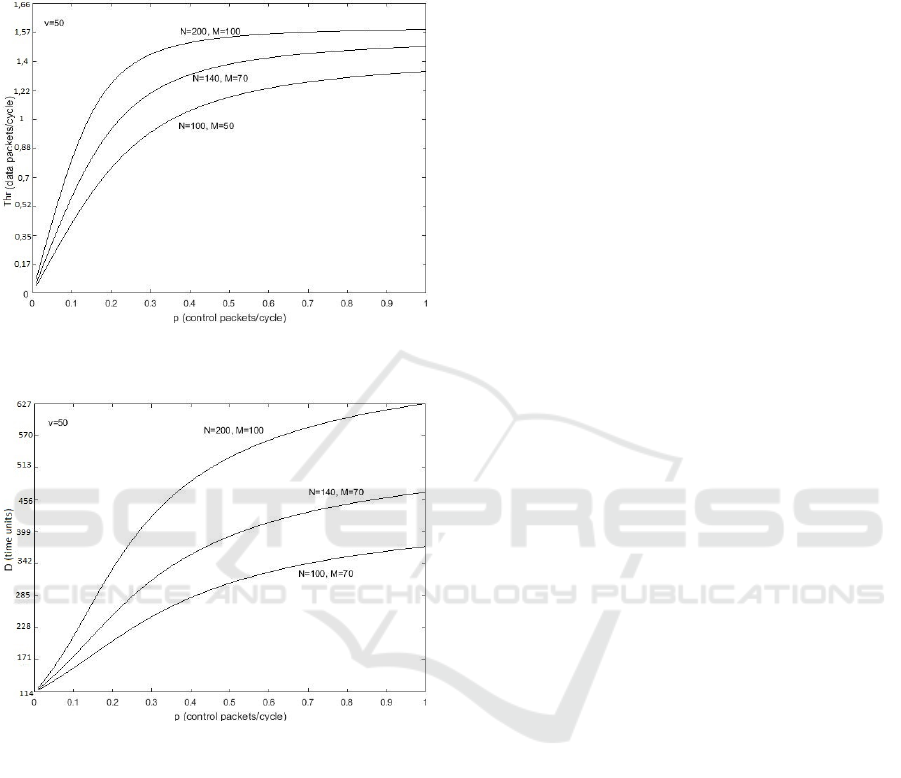
Fig. 3 shows the average throughput Thr versus
the birth probability p, for v=50 control mini-slots,
N=100, 140, 200 data channels. It is remarkable that
the Thr is an increasing function of N. For example
for p=0.9, the Thr is: 1.59 data packets/cycle for
N=200, 1.5 data packets/cycle for N=140, and 1.35
data packets/cycle for N=100. This is because as the
number N increases, the sets A
1
and A
2
of data
channels over which the number of stations with
successfully transmitted control packets distribute
their data packets, are getting larger. As a sequence,
the probability that more than two stations whose
control packets have been successfully transmitted
to have selected the same data channel for
OPTICS 2018 - International Conference on Optical Communication Systems
238
transmission is getting lower. Thus, as the number N
increases, the number of correctly transmitted data
packets over the data channels system increases too,
giving rise to the Thr values.
Figure 3: Throughput Thr versus birth probability p, for
v=50, N=100, 140, 200.
Figure 4: Delay D versus birth probability p, for v=50,
N=100, 140, 200.
Fig. 4 shows the average delay D versus the birth
probability p, for v=50 control mini-slots, N=100,
140, 200 data channels. As it is shown, the proposed
protocol behaviour when the number N increases
conforms to the above discussion. In other words, as
the number N increases and consequently the
number M increases, the total delay D is getting
higher. This is because as the number of stations
increases, the offered load to the system increases
too. In this case, the probability of control packets
collisions over the v control mini-slots rises. This
fact gives rise to the probability of a data packet
rejection when requesting access over the data
channels due to the applied wavelength assignment
algorithm. This is because, as the number M
increases the probability that more than two stations
whose control packets have been successfully
transmitted to have selected the same data channel
for transmission is getting higher. This is the reason
why, the total delay D reaches higher values.
5 CONCLUSIONS
In this paper, we explore an effective wavelength
assignment algorithm suitable for passive star WDM
LANs that use as single control channel. Our
objective is to improve the system performance by
dividing the set of multiple data channels into two
groups and by applying an efficient access scheme
that avoids the collisions over the WDM data
channels. An analytical model for the probabilistic
evaluation of the wavelength assignment is adopted,
while the performance measures of average
throughput and delay are derived by a Markovian
model study.
REFERENCES
Jun Zheng, and H. T. Mouftah, Optical WDM Networks:
Concepts and Design Principles. J. Willey & Sons Inc.
Publication - IEEE Press, 2004, pp. 3-6.
I.E.Pountourakis, “Performance Evaluation with Receiver
Collisions Analysis in Very High-Speed Optical Fiber
Local Area Networks Using Passive Star Topology”,
IEEE Journal of Lightwave Technology, Vol. 16, No.
12, pp. 2303-2310, Dec. 1998.
I.E.Pountourakis, P.A.Baziana, G.Panagiotopoulos,
“Propagation Delay and Receiver Collision Analysis
in WDMA Protocols”, in Proc. 5th International
Symposium on Communication Systems Networks and
Digital Signal Processing (CSNDSP 2006), Patra,
Greece, 2006, pp. 120-124.
P.A.Baziana: “An Approximate Protocol Analysis with
Performance Optimization for WDM Networks”,
Optical Fiber Technology, Vol. 20, Issue 4, pp. 414-
421, 2014.
P.A.Baziana: “Performance Analysis and Transmission
Strategies Comparison for Synchronous WDM Passive
Star LANs”, Springer Photonic Network
Communications Journal, Vol. 31, Issue 3, pp 457–
465, June 2016.
P.A. Humblet, R. Ramaswami, K.N. Sivarajan, An
Efficient Communication Protocol for High-Speed
Packet Switched Multichannel Networks, IEEE
Journal on Selected Areas Communications, Vol. 11,
pp. 568-578, 1993.
W. Szpankowski, “Packet switching in multiple radio
channels: analysis and stability of a random access
system,” Comput. Netw., vol. 7, no. 1, pp. 17–26,
1983.
Adaptive Channel Allocation Algorithm Suitable for WDM Networks: An Analytical Study
239

I.E.Pountourakis, P.A.Baziana: “Multi-channel Multi-
access Protocols with Receiver Collision Markovian
Analysis”, WSEAS Transactions on Communications,
Is. 8, Vol. 4, pp. 564-569, Aug. 2005.
P. Baziana, G. Fragkouli, and E. Sykas: “Analytical
Receiver Collisions Performance Modeling of a Multi-
channel Network”, in Proc. of the 2017 IEEE
Conference of Russian Young Researchers in
Electrical and Electronic Engineering (ElConRus
2017), Paper No. 008, Feb. 01-03, 2017, St.
Petersburg, Russia.
L. Comtet, Advanced Combinatorics: The Art of Finite
and Infinite Expansions, D. Reidel Publishing
Company, 1974, pp. 221-222.
APPENDIX
We explore the probability ]z)y(APr[ of z
successfully transmitted data packets over the N data
channels, conditional that y successful
(re)transmissions occurred during the v control mini-
slots, during a cycle, in case that
2y AND zy .
This problem is a special case of the problem studied
Baziana et al., (2017). Let:
Ed = The number of data channels from the set
A
1
where each of them has been selected by exactly
d stations whose control packets transmission was
successful, by the end of a cycle, where: d ϵ
[0,min(v,M)], Ed ϵ [0,N/2].
Md = The number of data channels from the set
A
1
where each of them has been selected by more
than d stations whose control packets transmission
was successful, by the end of a cycle, where: d ϵ
[0,min(v,M)], Ed ϵ [0,N/2].
Let be: M
2
=i.
J = The number of ways to choose the data
channels from the set A
1
in order at least one station
whose control packet transmission was successful to
have selectected each of them. It is:
iz
2
N
J
(15)
K = The number of ways in which the stations
whose control packet transmission was successful
can be chosen in order each of them to have
selectected a data channel from the set A
1
with no
other station to have selected it. It is
i2z
y
K
(16)
L = The number of possible replacements of stations
whose control packet transmission was successful
and that have selected a data channel from the set A
1
with no other station to have selected it. It is:
! i2zL
(17)
P = The number of ways in which the data channels
from the set A
1
can be chosen in order at least two
stations whose control packet transmission was
successful to have selectected each of them. It is:
i
iz
P
(18)
Q = The number of ways in which the data packets
from the stations whose control packet transmission
was successful can be distributed to the data
channels from the set A
1
in order at least two
stations to have selected each of them. It is:
i,i2zyS ! iQ
2
(19)
where the function S
2
(n,k) denotes the 2-associated
Stirling number of the second kind and provides the
number of ways n data packets from the stations
whose control packet transmission was successful
are distributed to k data channels from the set A
1
, in
order at least two packets to have selected each of
them. S
2
(n,k) is given by the retroactive equation
(Comtet, 1974):
)1k,2n(S
1
1n
)k,1n(kS)k,n(S
222
(20)
where:
Thus, in case that:
2y AND zy , it is:
i,i2zyS ! i
i
iz
! i2z
i2z
y
iz
2
N
N
2
)z,y(prob]z)y(APr[
2
2
z
ui
y
(21)
where:
zy:if ,0
zy:if ,1
u
(22)
Finally, we denote as
b
a
the integer part of the
division
b
a
.
OPTICS 2018 - International Conference on Optical Communication Systems
240
