A Training Simulator for Teleoperated Robots Deployed at CERN
Clare Saliba
1
, Marvin K. Bugeja
1
, Simon G. Fabri
1
, Mario Di Castro
2
,
Alessandro Mosca
2
and Manuel Ferre
3
1
Department of Systems & Control Engineering, University of Malta, Msida, Malta
2
Engineering Department EN-STI, CERN, Geneva, Switzerland
3
Centre for Automation and Robotics UPM-CSIC, Universidad Politecnica de Madrid, Madrid, Spain
Keywords: Teleoperated Robot, Telemax, EOD Robots, ROS, Gazebo, Modelling and Simulation, Robot Control, Virtual
Environment.
Abstract: This paper presents the design and implementation of a training simulator for the teleoperated robot Telemax.
Telemax is used at CERN for inspection and maintenance operations to reduce the exposure of personnel to
radiation. The robot is modelled using a robot description format and spawned in the robotic simulator
Gazebo. Control schemes are implemented in ROS in order to actuate the robotic arm in both joint-by-joint
space and operational-space. Control of the robot base is also modelled. A graphical user interface is used in
order to interface with the simulation, and control the robot with the help of live images coming from the
robot’s on-board cameras. The resulting simulator was tested by robot operators at CERN and is envisaged to
be of great help in the training of new operators, as well as in the testing of robot interventions in new scenarios
and environments.
1 INTRODUCTION
At the European Council for Nuclear Research
(CERN), the safety of personnel is given the utmost
importance. In fact, teleoperated robots are used for
inspection and maintenance in areas that are prone to
radiation contamination, such as in the Large Hadron
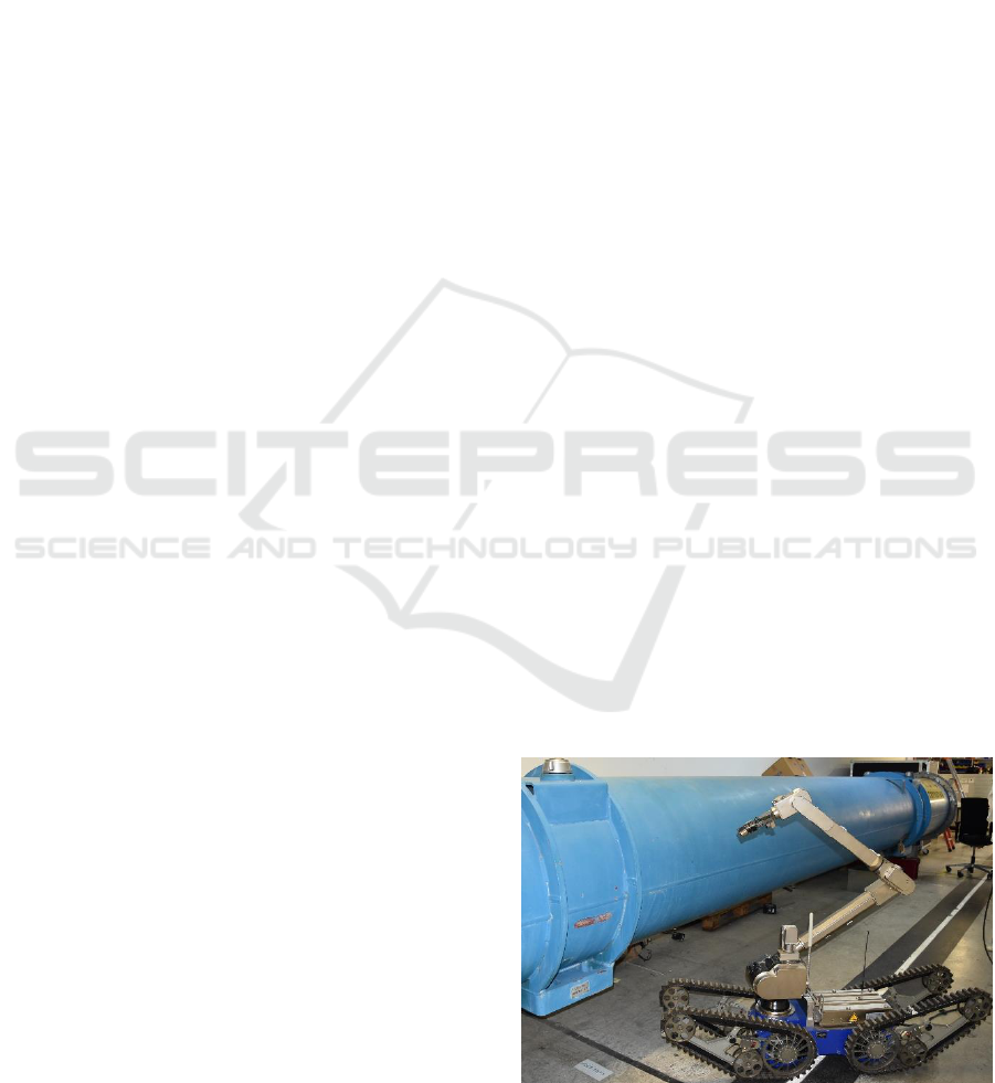
Collider (LHC). One of the robots used for this
purpose is Telemax which is shown in Figure 1.
Telemax is an explosive ordnance disposal (EOD)
robot manufactured by Telerob (Telerob, 2017). It is
equipped with tracked wheels for enhanced mobility,
with a seven degrees of freedom manipulator to
perform various tasks, and with six colour cameras
used for inspection and to provide visual feedback
during teleoperation.
Operators need to be well trained to use such
robots during various complex interventions.
However, the robots are not always available for
training, and it can be unsafe for a novice operator to
test dangerous manoeuvers on the real robot itself.
Moreover, it can be risky to try out new manipulation
procedures on the real robot since it can lead to
expensive damages. In such situations, the use of
training simulators is very convenient. Training
simulators are a virtual medium where the operators
can use a virtual imitation of the robots to learn how
to operate them safer and better.
In literature, one can find a number of works on
EOD robot simulators. In (Li et al., 2007) information
is provided about the software used to build both the
robot model and its simulated environment. In
addition, the authors document the kinematic model
of their robot, the collision detection algorithm and
how to grade the training system. Schoor et al. (2012)
present the training stages of EOD robots, and the
Figure 1: The teleoperated robot, Telemax, during one of its
maintenance procedures at CERN.
Saliba, C., Bugeja, M., Fabri, S., Castro, M., Mosca, A. and Ferre, M.
A Training Simulator for Teleoperated Robots Deployed at CERN.
DOI: 10.5220/0006849302830290
In Proceedings of the 15th International Conference on Informatics in Control, Automation and Robotics (ICINCO 2018) - Volume 2, pages 283-290
ISBN: 978-989-758-321-6
Copyright © 2018 by SCITEPRESS – Science and Technology Publications, Lda. All rights reserved
283
operational requirements for realistic training
simulation, such as 3D rendering techniques. Their
paper also discusses a number of challenges that are
typically encountered when building robot
simulations, such as the challenge to simulate
gripping. However, neither of the aforementioned
works gives any detail on the robot simulation
software itself, such as how the robot was visually
modelled and how the control system was
implemented.
Szenaris GmbH, a company that supplies training
and simulation solutions, has put on the market a
virtual reality robotic vehicle simulation (Szenaris
GmbH, 2016) for both teleoperated robots, Telemax
and Teodor. The software can control the arm, base,
and camera using the actual remote control of the
vehicles Telemax and Teodor in a virtual training
environment, such as in an aircraft or in a building.
Unfortunately, this software does not allow the user
to customise the robot model and its virtual
environment. For this reason, it cannot be used with
altered robot models, such as to reflect hardware
changes and add-ons, or to design custom training
scenarios. As expected, the inner workings of this
software are not documented in literature.
For this reason, it was decided that in order to
have the required customisability and full flexibility
to generate new training scenarios and other features,
it is best to design and implement a custom robot
simulator using generic robot simulation software
that includes physics and visualisation engines. This
is the main contribution of the work reported in this
paper.
Various commercial, as well as open-source
software for simulation of different robots is
available. Gazebo, as reported in the survey by Ivaldi
et al. (2014), is one of the most used and popular robot
simulation software. Gazebo offers a robust physics
engine, high quality graphics, and convenient
programming and graphical interfaces. It also offers
applications such as data visualisation, simulation of
remote environments, and even reverse engineering
of black-box systems. In Gazebo all objects have a
defined mass, velocity, friction, and other physical
attributes. Hence, when a force is exerted on an
object, all the physics is simulated for a realistic
behaviour. Gazebo maintains all functions provided
by the physics engine, open dynamic engine (ODE),
to simulate the dynamics and kinematics of bodies.
Gazebo is also compatible with ROS (Quigley et al.,
2009). ROS is a robot framework that can be used to
write code for robot control, and is adaptable to
different robot platforms. In this work, Gazebo is
used as the robotic simulator, with ROS acting as the
middleware between the user and the model in order
to control the robot model in Gazebo. Apart from the
benefits found in literature, Gazebo and ROS were
chosen since these software were already used at
CERN for other projects. Hence, it is easier to
integrate all projects together.
2 SYSTEM OVERVIEW
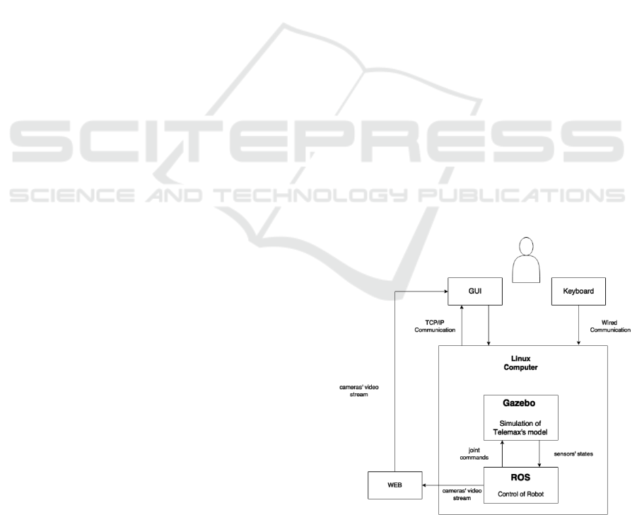
Figure 2 provides an overview of the designed
simulator and its operation. The generic robotic
simulator Gazebo, which runs on a Linux computer,
is used to simulate the physics and the visuals of the
realistic and functional custom-made model of
Telemax. Thus, Gazebo can provide all the sensors’
states, including the state of all the joints declared in
the model of the robot, as well as information on the
cameras that Telemax is equipped with, since these
are also modelled and simulated. On the other hand,
ROS is used to actuate the robot via the available
control library, get the required actuators’ data from
the controllers developed in the mentioned library,
and send it to Gazebo to actuate the joints. The user
can operate the simulator using either a keyboard or a
specifically designed GUI that runs on Windows. In
order to capture the information from the user,
analyse it, and feed it to ROS, executable programs
were written. The output of virtual cameras is also
streamed on a web server using ROS libraries. This
allows the user to access the cameras’ data and have
it displayed in real-time via the GUI.
Figure 2: Block diagram of the operation of the simulator.
ICINCO 2018 - 15th International Conference on Informatics in Control, Automation and Robotics
284
3 SYSTEM MODELLING
For the simulator to be as realistic as possible, both
the mathematical and visual models of the robot
needed to be as faithful to the real robot as possible.
The mathematical model of the robot was derived and
tested. This was followed by the visual modelling of
the robot using a robot description format.
Furthermore, a simple test environment was also
modelled for the robot to operate in.
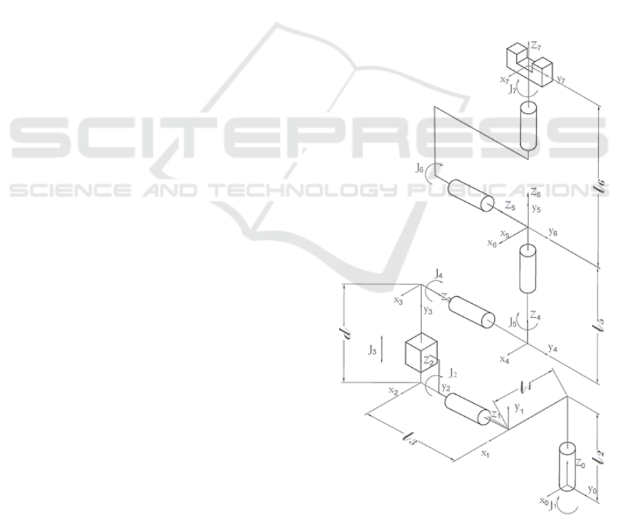
3.1 Kinematic Model of the Robotic
Arm
The first step in obtaining the kinematic model of
Telemax’s robotic arm, was to determine the Denavit-
Hartenberg parameters. In this manner the reference
frames could be attached properly to the links of the
robot’s arm. This was done by accurately sketching
the robotic arm’s configuration, to clearly show all
the joints and their frames as depicted in Figure 3.
Then, the Denavit-Hartenberg convention (Sciavicco
and Siciliano, 2005) was used to generate the
transformation matrix of each link with respect to the
parent link. At the end, the transformation matrix
between the base reference frame and the end-effector
was found by multiplying all transformation matrices.
3.2 Physical Model of Telemax
The first step in modelling a robot in ROS is to create
a 3D mock-up of the robot in a CAD modelling tool
such as Inventor (Autodesk, 2017). Then, each link of
the model that has a different degree of freedom is
exported in the STL file format (since it is a geometry
file format supported by URDF). This enables the
links to perform different movements once in
operation. The model is simulated in ROS by using
URDF (Coleman, 2013).
URDF is an XML format that describes a robot
model, its links, and the joints connecting the links
together. The link element describes the body, both
kinematically and dynamically. This includes the
visual part of the body, the collision part, and its
inertial properties. The collision and inertial
properties are important to model the robot in
Gazebo. The joint is defined by the joint type, in this
case there were: six revolute joints and one prismatic
joint for the robotic arm. Another four revolute joints
were defined for the flippers of the robotic base.
Furthermore, each joint is defined by its joint
position. The limitations of rotation or extension, and
the maximum joint effort and velocity are also
defined for each joint. The position of the frames of
the non-fixed joints were set according to the
kinematic chain derived. Another useful element used
is the transmission element. This element describes
the relationship between joints and their actuators.
The cameras mounted on the robot are also modelled
using an ROS plugin, the camera_controller plugin
(Gazebo, 2017). This plugin acquired the cameras’
data from Gazebo and outputs it to the user as an
image. Once the model is defined, it is spawned into
Gazebo.
3.3 Physical Model of the Environment
A simple test environment was also set up using a
procedure similar to that followed to build the model
of the virtual robot. A custom training scenario was
built to test the basic functionalities of the robot. This
includes stairs and ramps, and different objects that
are used to test grasping and handling training
procedures.
Figure 3: The joints and links comprising Telemax's robotic
arm.
A Training Simulator for Teleoperated Robots Deployed at CERN
285
4 SYSTEM DESIGN
4.1 Control of the Robot’s Joints
To actuate the joints of the robot, the ros_control
(Lamprianidis, 2017) package in ROS is used. A ROS
controller is assigned to each of the robot’s joints. The
controller needs to be compatible with the hardware
interface declared in the transmission tag in the
URDF. This is because the hardware interface acts as
the mediator between the controller and, in this case,
the simulator. It is able to convert from joint torques
to motor torques, and gives access to read and
command actuator properties in Gazebo. On the other
hand, the ROS controller uses a feedback mechanism
where the controller receives a reference value, such
as a desired joint angle, and varies the control variable
(or effort) to adjust the controlled output accordingly,
based on the signals fed back from the sensors. The
closed-loop control scheme uses a Proportional
Integral Derivative (PID) loop.
The joint position controller and the effort joint
interface are implemented on the joints of the robotic
arm and the joints of the flippers. However, during
teleoperation, the user cannot control the joints by
sending a reference angle, but rather by sending a
desired velocity. Hence, a velocity controller needed
to be emulated to change the velocity reference input
from the user to a reference position of the joints
(angle in case of revolute joints). This is done by
incrementing the angle or position value of each joint
with a constant value every time a specific key on the
keyboard is pressed and until the key is released.
Thus, the joints move with a constant velocity. If the
velocity needs to be changed, the user can decrease or
increase the constant value of increment until it
reaches its limits.
4.2 Design of the Robotic Arm Control
System
The robotic arm can be controlled in two modes,
either in a joint-by-joint control mode or in
operational-space control mode. In the former the
user controls each joint individually. In the
operational-space control mode, the user specifies the
required end-effector position and orientation in
operational space (also referred to as Cartesian
space). Then, a controller is used to find the required
joint variables, q
d
, so that the manipulator reaches the
reference position and orientation in 3D space.
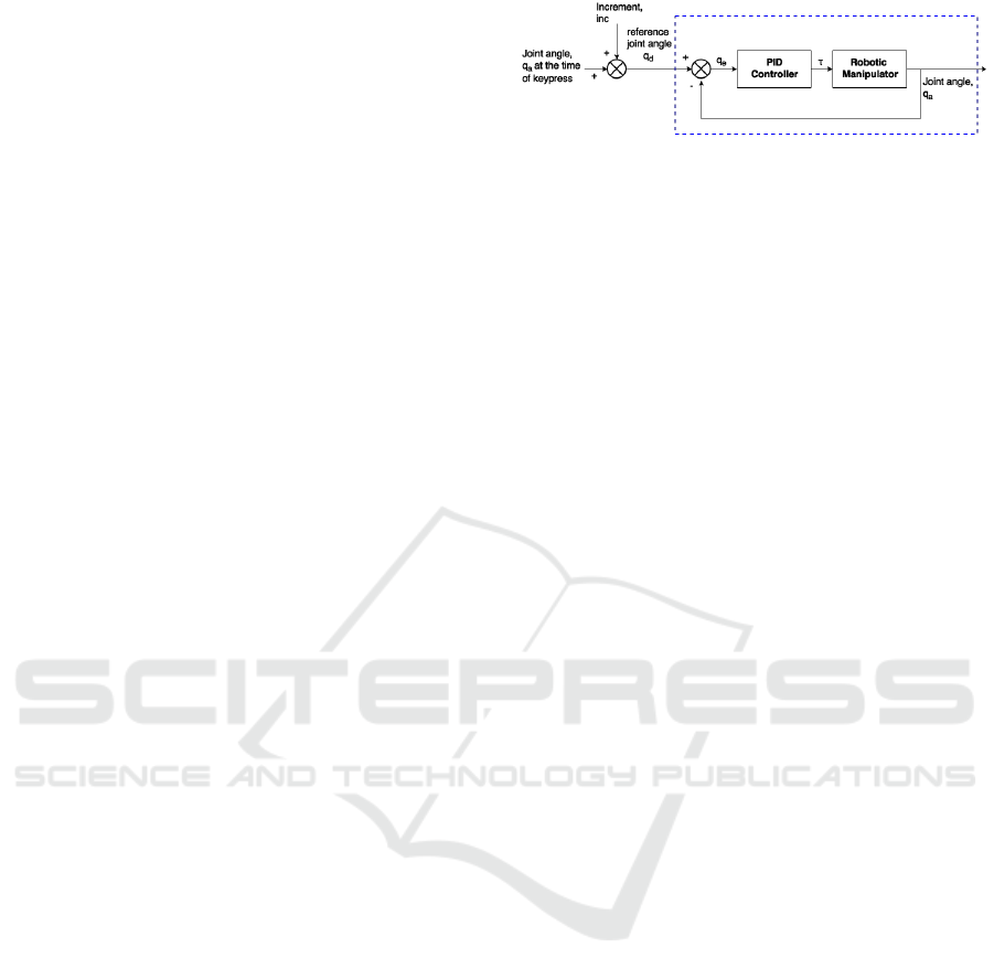
Figure 4 depicts the adopted joint-by-joint control
scheme. Every time the user presses the keyboard
Figure 4: Joint-by-joint control scheme.
button corresponding to a joint, the current actual
joint angle (in case of revolute joints) or joint position
(in case of prismatic joints) q
a
is read from Gazebo
and increased (or decreased) by adding (or
subtracting) the constant value, inc. This constant is
set according to the speed predefined by the user.
Consequently, the desired joint angle, q
d
, is
computed. This value is then sent to the joint angle
controller that uses an internal feedback mechanism
to calculate the torque required to actuate the joints
according to the PID control algorithm. The
controller developed in ros_control is enclosed in the
blue dotted box in Figure 4 and allows only the
reference joint position as an input.
The operational-space control scheme is shown in
Figure 5. Once the user activates the operational-
space control mode, the actual joint angles q
a
are used
to find the matrix x
a,
containing the orientation R(q
a
)
and the position P(q
a
) (as in (1)) of the end-effector,
by performing the forward kinematics.
(1)
Then, each time the user needs to change the
position/orientation of the end-effector, the new
desired rotational matrix x
d
which is a function of the
desired joint angles q
d
is found using the
incrementing vector, inc. This vector contains six
constants, three that give an increment in the x, y, and
z axis of the end-effector (
, and
three that give a rotation around the x (yaw), y (pitch),
and z (roll) axis (
. To find the
new position of the end-effector, the first three
constants of inc are added with the current x, y, and z
position (
as follows
(2)
To find the orientation of the new frame, R(q
d
), as
denoted by Siciliano and Sciavicco (2005), the
composition of successive rotations with respect to a
fixed frame is obtained by premultiplying of the single
rotation matrices in the order of the given sequence of
rotations.
ICINCO 2018 - 15th International Conference on Informatics in Control, Automation and Robotics
286
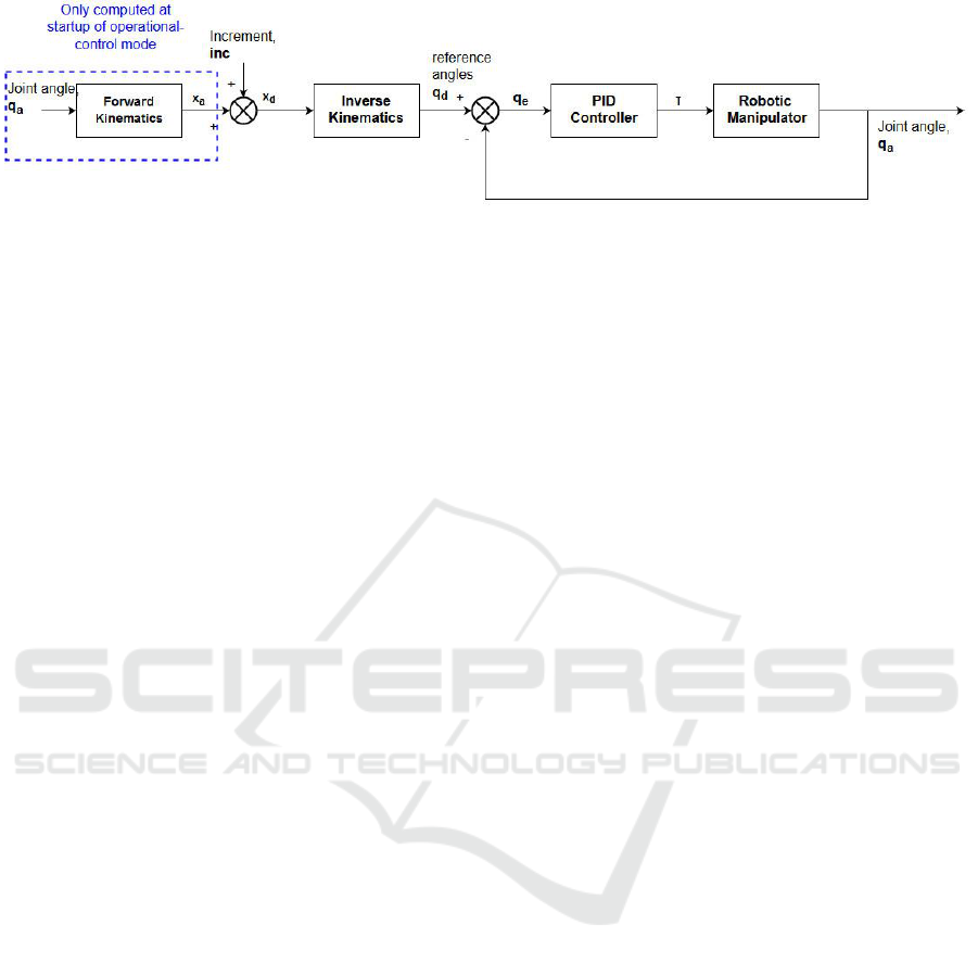
Figure 5: Operational-space control scheme.
Hence,
(3)
where, is the orientation matrix as a
function of the desired increment angles
(
. Hence, this matrix gives the
desired rotation transformation. In (Sciavicco and
Siciliano, 2005), the authors also show that the
orientation matrix R(ϕ) is given by
(4)
In this equation, c and s denote the cosine and sine
trigonometric functions of the subscript angle
respectively.
Taking,
(5)
the set of angles in (5) are computed in (4), and the
orientation matrix that the actual coordinate frame
needs to be rotated with, is found. In order to find the
final desired orientation matrix, R(q
d
), R(q
a
) and
R(ϕ) are multiplied together as in (3). Once the
required rotation matrix x
d
, is found, one can move
on to change from the coordinate space to the joint
space. To find the joint variables required for the
robotic arm to move to the desired position and
orientation, the inverse kinematics are computed on
the desired frame. Following this, the newly
computed reference joints are passed through the joint
angle controller that is the same as that used in the
joint-by-joint control.
For the computation of the kinematics that were
used in the operational-space control, the Kinematics
and Dynamics Library (KDL) (Orocos, 2017a) by the
Orocos Project (Orocos, 2017b) was used. It provides
generic forward and inverse kinematic solvers by the
use of numerical solutions. The forward kinematic
solver of KDL is used in real time to calculate the
forward kinematics of the manipulator. To calculate
the inverse kinematics, the solver TRAC-IK (Beeson
and Ames, 2015) was used. TRAC-IK gives solution
in a relatively low computational time whilst taking
in consideration the joint limits. The gripper of the
robotic arm was also modelled and controlled in a
similar way to the joint-by-joint control scheme. The
gripper consists of six revolute joints which are
moved simultaneously in order to open and close its
claws.
4.3 Control of the Robot Base
The mobile base of Telemax consists of four flippers
which can be rotated clockwise and anti-clockwise
for better maneuverability and to make the base reach
different heights. These flippers are modelled in ROS
as revolute joints and are controlled in a similar
manner to the joint-by-joint scheme. Telemax is also
equipped with tracked wheels. Since Gazebo does not
support tracked vehicles, a way around the issue of
simulating the tracked wheel behaviour needed to be
found. A plugin developed by Team Hector (2017)
was used to simulate the wheels. The motion is led by
a simple controller that exerts forces on the main
robot based on commanded linear and rotational
velocities.
4.4 Graphical User Interface
The user can interface with the simulator via a
keyboard, by which the user can switch from one
mode to another and move the robotic arm, or the
robot base, using the assigned key. Furthermore, The
interface is shown in Figure 6, a GUI developed by
the robotics team at CERN (Lunghi, Marin Prades
and Di Castro, 2016) is interfaced with the simulator.
The user can control the robot using a keyboard or a
A Training Simulator for Teleoperated Robots Deployed at CERN
287
joystick and can only use the output of the cameras
mounted on the robot for teleoperation.
Figure 6: The GUI used with the simulator.
5 RESULTS
To achieve the best computational performance,
different parameters of the physics engine were
adjusted in a heuristic manner, in order to reach a
compromise between the accuracy of the simulation
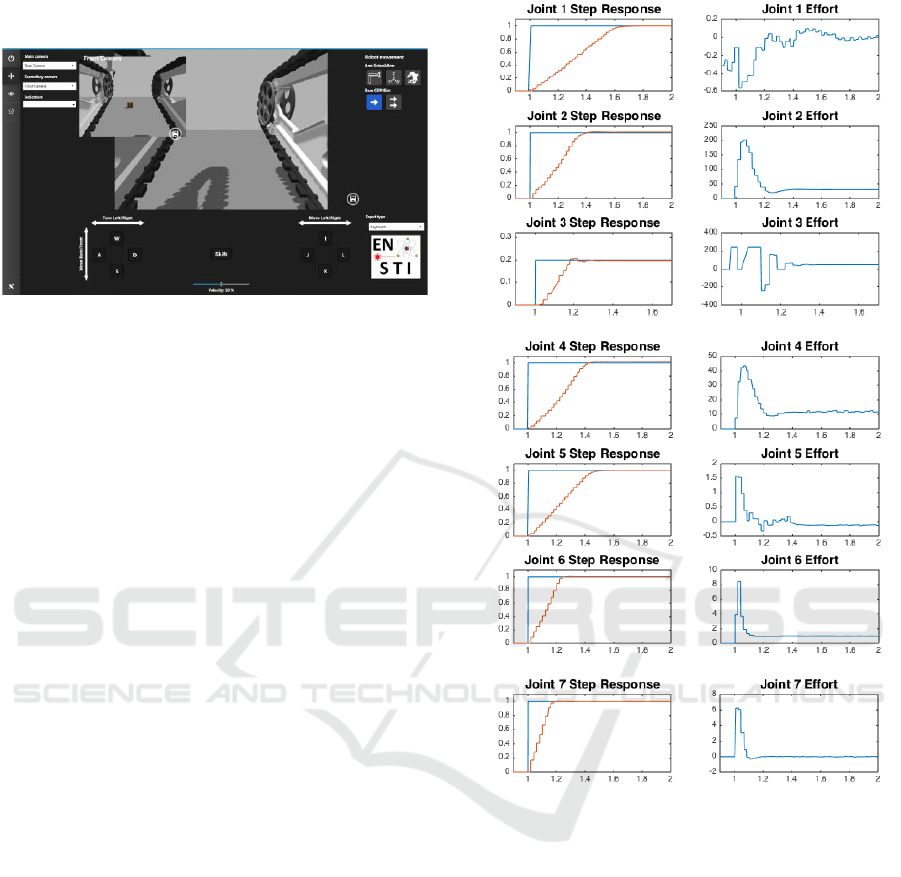
and its performance. Then, the step response of each
joint was analysed in order to tune the corresponding
PID parameters for a non-oscillatory, accurate but
fast response. The results are shown in Figure 7,
where (a) shows the step responses for each joint of
the manipulator and (b) shows the effort of each joint
of the manipulator.
In order to test the operational-space control
scheme, the robotic arm was programmed to follow
different trajectories, both in 2D and 3D, leaving the
base at rest. The base was left at rest since during
interventions, at CERN, the control and movement of
the manipulator is done whilst the base is stationary.
This test was done by feeding the desired coordinates
in the x, y, and z axes into the operational-space
control scheme. Figure 8 shows the robotic arm
tracking a spiral trajectory with very little error. Some
minor deviations are noticed in Figure 8 and these are
attributed to the PID’s inability to compensate fully
for the system’s coupling effects and nonlinearities.
The gripper of the robot was tested by grasping
different objects that have different weights and
shapes, such as a pallet as seen in Figure 9. The
experiments included also grasping and carrying
around a briefcase, grabbing a small cube from one
box and placing it into another one by using only
visual feedback from the on-board cameras. As in
reality, the operator can deduce that an object is
grasped either visually or by performing some
movements with the arm such as moving the arm
upwards.
Time (seconds)
(a)
Time (seconds)
(b)
Figure 7: (a) shows the step response for each joint, where
the blue graph shows the reference input and the red graph
shows the controlled joint variables. (b) shows the effort
force (Nm) of each joint.
Figure 10 shows a testing exercise of the
simulated robotic base. In this test the operator drove
the robot around a maze and made it climb different
obstacles. By controlling the flippers of the robot,
Telemax was able to successfully climb up a
maximum height of 50 cm. Finally, Figure 11
provides a complete picture of the simulation in use.
Joint Torque (Nm)/Joint Force (N)
Joint Angle (rad) / Joint Length (m)
ICINCO 2018 - 15th International Conference on Informatics in Control, Automation and Robotics
288
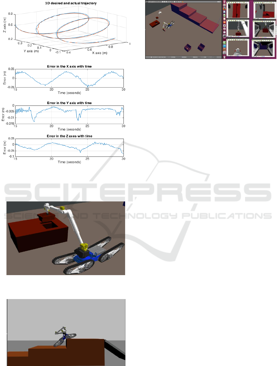
Figure 8: Tracking of a 3D spiral trajectory. Blue plot shows
the desired path and red plot shows the path followed. Error
with time in the x, y, z directions are shown underneath for
each trajectory.
Figure 9: Telemax robot operated to grasp and handle
objects.
Figure 10: Telemax operated to climb up stairs by setting
the flippers accordingly.
Figure 11: Telemax simulation using visual feedback from
the on-board cameras of teleoperation.
The figure shows the robot being operated in a virtual
environment in Gazebo and it also shows the visual
feedback from its onboard cameras made available to
the operator. These exercises help users to gain
confidence in the control of Telemax.
6 CONCLUSIONS
This paper presented the physical and dynamic
modelling of a realistic simulated version of the robot
Telemax, as well as its controller in its working
environment. The virtual robot was designed,
implemented, and simulated in the generic robotic
simulator Gazebo. The physical model was built
using the robotic description format, URDF. To set an
interface between the user and the robot, and the robot
and the simulator, ROS was used. ROS was also used
in order to implement the control algorithms of the
robot.
The robotic arm was modelled by deriving its
kinematic equations. Then, a control system was
implemented to drive the robotic arm in two different
modes, namely: joint-by-joint mode and operational-
space mode. The gripper was also modelled to open
and close accordingly. The drive of the robotic base
was also developed by using a velocity control loop
where the linear or angular reference velocity of the
base is specified and varied by the user in real-time.
Furthermore, another angle control loop is used for
the control of the four flippers of the robotic base.
For the main operation of the robot, a keyboard as
well as a GUI developed at CERN for the
teleoperation of the robots, were interfaced with the
simulator. As in real scenarios, the robots are
teleoperated, hence the operators use the cameras
mounted on the robot for visual feedback. These
cameras were also modelled so that the user can make
use of them to control the robot during training. This
helps the user gain more confidence in teleoperation.
Finally, tests were performed to evaluate the
robustness of the system developed.
A Training Simulator for Teleoperated Robots Deployed at CERN
289

To render the system more realistic, future work
can interface the actual remote control with the
simulator, such that the user obtains the same feel as
when operating the real robot. Furthermore, a better
solution needs to be found to simulate the tracked
wheels. Moreover, the gripping function of the robot
needs to be tested on more objects that differ in shape
and weight to test the robustness of the simulator in
this respect.
In conclusion, a simple to use, low-cost,
reprogrammable and effective training simulator for
the EOD robot Telemax was developed. Operators of
Telemax at CERN performed some tests with the
robotic arm and the drive of the robot. Positive
feedback about the training simulator in general was
given. The operators agreed that such simulator is
easy to use and the manipulation is very realistic.
Furthermore, the operators stated that such tool is
very useful in the training procedure both for new
operators as well as for training before interventions.
One of the advantages of having such a model is that
it can be adapted and tested in different scenarios.
Moreover, using this system, other robots can be
modelled and allowed to interact together in Gazebo.
Hence, when operators are on the real scene, time is
gained as operators are prepared before hand.
ACKNOWLEDGEMENTS
This research was supported by Endeavour
Scholarship Scheme 2016 (Malta) and CERN Trainee
Programme.
REFERENCES
Autodesk (2017) Inventor. Available at: https://www.auto
desk.com/products/inventor/overview (Accessed: 27
September 2017).
Beeson, P. and Ames, B. (2015) ‘TRAC-IK : An Open-
Source Library for Improved Solving of Generic
Inverse Kinematics’, pp. 928–935.
Coleman, D. (2013) urdf. Available at: http://wiki.ros.org/
urdf/XML (Accessed: 2 September 2017).
Gazebo (2017) Gazebo plugins in ROS. Available at:
http://gazebosim.org/tutorials?tut=ros_gzplugins
(Accessed: 4 September 2017).
Ivaldi, S., Padois, V. and Nori, F. (2014) ‘Tools for
dynamics simulation of robots: a survey based on user
feedback’, CoRR, p. 15. doi: 10.1109/HUMANOIDS.
2014.7041462.
Lamprianidis, N. (2017) ros_control. Available at:
http://wiki.ros.org/ros_control (Accessed: 9 September
2017).
Li, X. et al. (2007) ‘Research on simulation and training
system for EOD robots’, 2006 IEEE International
Conference on Industrial Informatics, INDIN’06, pp.
810–814. doi: 10.1109/INDIN.2006.275666.
Lunghi, G., Marin Prades, R. and Di Castro, M. (2016) ‘An
advanced , adaptive and multimodal graphical user
interface for human-robot teleoperation in radioactive
scenarios’, ICINCO, 2, pp. 224–231.
Orocos (2017a) KDL wiki. Available at: www.orocos.
org/kdl (Accessed: 16 September 2017).
Orocos (2017b) The Orocos Project. Available at: http://
www.orocos.org (Accessed: 16 September 2017).
Quigley, M. et al. (2009) ‘ROS : an open-source Robot
Operating System’.
Schoor, W., Förster, M. and Radetzky, A. (2012) ‘Realistic
training simulations of explosive ordnance disposal &
improvised explosive device disposal robots’, IEEE
International Conference on Industrial Informatics
(INDIN), 49(0), pp. 875–880. doi: 10.1109/INDIN.
2012.6300831.
Sciavicco, L. and Siciliano, B. (2005) Modelling and
Control of Robot Manipulators. Second. Springer.
Szenaris GmbH (2016) Remote Controlled Vehicle
Simulation. Available at: https://www.szenaris.com/
wp-content/uploads/2016/09/szenaris_ausbildungsaus
stattung_manipulatorfahrzeuge.pdf (Accessed: 3
August 2017).
Team Hector (2017) Team HECTOR. Available at: http://
www.teamhector.de (Accessed: 10 September 2017).
Telerob (2017) Telerob. Available at: http://www.telerob.
com/en/products (Accessed: 16 August 2017).
ICINCO 2018 - 15th International Conference on Informatics in Control, Automation and Robotics
290
