
VDES Performance Evaluation for Future e-navigation Services
M. Luglio, C. Roseti and F. Zampognaro
∗
University of Rome Tor Vergata, Via del Politecnico 1, 00133 Rome, Italy
Keywords:
VDES, AIS, Satellite, VHF, e-navigation, Simulation.
Abstract:
E-navigation aims at increase safety and efficiency of navigation, defining reliable data exchange formats and
communication channels between either ship to ship or ship to shore. New technological advancements start
from the consolidation of Automatic Identification System (AIS), which is mandatory in some classes of ships
for the notification of the position and to send distress signals. In pair with AIS baseline services, additional
services are gaining momentum and are available in state of the art equipment, including the handling of sen-
ding and receiving Application-Specific Messages (ASMs). In this direction, the VHF Data Exchange System
(VDES) standard was recently introduced, to improve on both messaging capabilities and system flexibility
(standardizing the use of satellite channels) as well as to allow higher bitrates for application messages with
regard to AIS and ASM. In this paper, we reviewed the main characteristics of VDES, then we carried out
a technical analysis of the new communication standard in terms of channel compositions, supported rates,
access schemes and latency. Finally, we focus on the performance of two possible future VDES applications,
namely “dematerialization” and “towage” through a MATLAB model of the VDES communication channels.
1 INTRODUCTION
The International Maritime Organization (IMO) de-
veloped the e-navigation strategy to increase safety
of navigation through a better organization of data on
ships and on shore, better data exchange and com-
munication between ships or ship to shore (and vice-
versa). According to the official IMO definition, e-
navigation is “the harmonized collection, integration,
exchange, presentation and analysis of marine infor-
mation on board and ashore by electronic means to
enhance berth to berth navigation and related servi-
ces for safety and security at sea and protection of
the marine environment”. E-navigation has been for
long time associated to Automatic identification sy-
stem (AIS) (IMO, 2001) technology, using commu-
nication in VHF bands and offering a transmission
range of up to 10–20 nautical miles, accordingly to
the used equipment.
AIS is an important framework for safety of na-
vigation and it is a carriage requirement defined by
the International Convention for the Safety of Life
at Sea (SOLAS) for big-sized vessels (e.g, 300 tons
and upwards). Because of its effective and useful
technology, the use of AIS is often extended to vessels
not complied with the carriage requirement (i.e., AIS
∗
Authors in alphabetical order
Class-B) and allows other applications such as Aids
to Navigation (AtoN), Application Specific Messages
(ASM), Search and Rescue Transmitter (SART), Man
Over-Board unit (MOB) and Emergency Position-
Indicating Radio Beacon (EPIRB-AIS). This exten-
ded use of AIS technology has caused significant in-
crease in VHF Data Link (VDL) load, which has be-
come an active concern in IMO and International Te-
lecommunication Union (ITU).
Because of increasing general demand of radio
spectrum for digital communication (mobile pho-
nes and data), ITU issued recommendation ITU-R
M.1842 (ITU, 2009) to define characteristics of an en-
hanced VHF radio systems for maritime mobile servi-
ces. In addition, ITU defined techniques for efficient
and standardized maritime communications at higher
data rates (up to 32-fold) providing the core element
of the upcoming VHF data exchange system (VDES),
which has been standardized in the 2015 with the re-
commendation ITU-R M.2092-0 (ITU, 2015).
VDES aims at first complementing/extending and
in the next future (tentatively by year 2019-2022), re-
placing current AIS, by providing a vast gamut of data
exchange channels and methods. Thereby, the AIS ra-
dio channels will be resilient to overload as AIS po-
pulations increase, and new services will be enabled
by the progressive introduction of alternative VDES
channels.
Luglio, M., Roseti, C. and Zampognaro, F.
VDES Performance Evaluation for Future e-navigation Services.
DOI: 10.5220/0006850200670075
In Proceedings of the 15th International Joint Conference on e-Business and Telecommunications (ICETE 2018) - Volume 1: DCNET, ICE-B, OPTICS, SIGMAP and WINSYS, pages 67-75
ISBN: 978-989-758-319-3
Copyright © 2018 by SCITEPRESS – Science and Technology Publications, Lda. All rights reserved
67
VDES supports terrestrial data communication as
well as a satellite component, leveraging VHF ra-
dio channels. The traditional SAT-AIS (ESA, 2018)
was provided as an added option to exploit the ad-
vantage of global satellite coverages for AIS broad-
casting beyond the coastal areas, without increasing
the actual terminal capabilities. On the contrary, the
combined use of terrestrial and satellite channels is
defined in the early stages of the VDES standards, as
a design requirement. This represents an opportunity
to offer worldwide coverage and facilitate the imple-
mentation of interoperable e-navigation and moderni-
zation of the Global Maritime Distress Safety System
(GMDSS) by specific optimizations coming from the
use of satellite communications.
The evaluation of VDES theoretical performance
as inferred by a critical analysis of the standards is
the first focus of the paper. Next, taking as a refe-
rence two VDES-compliant applications defined in
the frame of an ongoing European Space Agency
(ESA) project, named MARVELOWS (ESA, 2017),
a preliminary feasibility study through a simulation
campaign is presented and discussed.
2 VDES OVERVIEW
The VDES aims to provide an effective and efficient
use of radio spectrum, enhancing the capabilities of
AIS and addressing the increasing requirements for
data exchange. New VDES channels and techniques
enable higher data rates than those used for AIS. Furt-
hermore, VDES network protocol is optimized for
data communication so that each VDES message can
be transmitted with a high confidence of reception, on
either terrestrial or satellite VHF channels.
The VDES system supports the unique identifica-
tion and location of all active maritime stations as a
default service. For the purpose of identification, the
Maritime Mobile Service Identity (MMSI) is used,
as defined in the latest version of Recommendation
ITU-R M.585 (ITU, 2012). Therefore, VDES com-
prises the functions of the existing AIS, the additional
communication links for the exchange of Application
Specific Messages (ASM) and further dedicated com-
munication links enabling dedicated higher capacity
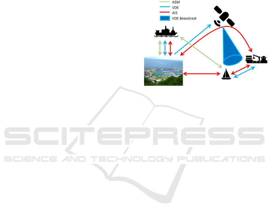
VHF data exchange (VDE). Figure 1 depicts possible
VDES communication options and includes in parti-
cular:
– Shore-to-ship (and vice versa) VHF terrestrial
communications for AIS, VDE and ASM servi-
ces;
– Ship-to-ship (and vice versa) VHF terrestrial
communications for AIS, VDE and ASM servi-
ces;
– Shore-to-ship (and vice versa) VHF satellite aided
AIS services;
– Satellite broadcasting services for e.g., VDE mes-
sages of general interest.
Figure 1: VDES/AIS communication framework.
VDES is currently a work-in-progress activity,
where in the period 2019–2020 VDES is expected to
replace AIS and evolved ASM services, to be part in
year 2021 of a generalized maritime access, including
Satellite channels. Therefore, today is the right time
to define and study advanced services over VDES, ex-
ploiting the additional capabilities introduced by the
terrestrial component (first to be introduced according
the the VDES implementation roadmap), and by the
satellite component later on.
3 USE OF VDES FOR FUTURE
E-NAVIGATION SERVICES
The availability of a standardized messaging system
extending current AIS capability will allow in the near
future to define a wide set of standardized enhanced
e-navigation services, tailored to specif user require-
ments and use cases.
Currently, several use cases associated to speci-
fic services are being defined. For instance we have
the UKCM (Under Keel Clearance Management), de-
fined by the Australian Maritime Safety Authority,
Route Exchange Ship to Ship, Logistic services, etc
(The Nautical Institute, 2015).
In this direction, the European Space Agency
(ESA) project named “Maritime Applications exploi-
ting Reliable VHF data Exchange LOW cost System”
(MARVELOWS) (ESA, 2017), provided a feasibi-
lity study of VDES-related services starting from a
complete understanding of the users and stakeholders
DCNET 2018 - International Conference on Data Communication Networking
68

needs. In particular, MARVELOWS project foresees
the development of two upcoming VDES services:
– Dematerialization, which is aimed to share in-
formation among vessels navigating the same ge-
ographical area, typically delivered on paper on
a weekly or even monthly frequency, in addition
to nautical charts exchange and weather forecast
updates.
– Towage, which provides a technological support
for real-time communications between personnel
on the field and headquarter during towage ope-
rations. The main information that could be ex-
changed are: start and end of the service, routes
and anchorages, crew list, weather now-casting.
The definition of the corresponding use-cases
(UCs) and operational scenarios has been then ba-
sed following the IALA Guideline 1117 “VHF Data
Exchange System (VDES) Overview” resulting in the
identification of the following combination of IALA
UCs, which for MARVELOWS Dematerialisation
service are:
– UC5 Chart updates and publications;
– UC6 - Route exchange.
and for MARVELOWS Towage service are:
– UC7 Logistic and services.
In all these UCs, it is requested to perform one
or a combination of ship-to-shore, shore-to-ship and
ship-to-ship data exchange, with different communi-
cation requirements, which will affect the configura-
tion of the VDES system. Such communication re-
quirements are:
– Message size - either short or longer messages are
possible; message size affects the selection of a
specific VDES channel configuration and access
scheme;
– Message timing - this indicates how frequent send
a message and which scheduling scheme to adopt:
periodic or sporadic/event-drive. This parameter
affects as well the selection of a specific access
scheme;
– Message reliability - Reliability refers to the gua-
rantee of a message reception. Within some
access schemes, collisions are possible with sub-
sequent transmission failure. It is possible
either to avoid collision (through suitable access
scheme) or implement a retransmission function
at the application layer;
– Real-Time delivery - A time interval may occur
between the data availability and its actual trans-
mission. It is possible to properly tune this time
by properly select the access scheme.
More specifically, and in relation to message ti-
ming, the following classification can be taken as a
general reference from the standards:
– Static information. Every 6 minutes or when data
is amended (on request);
– Dynamic information. Dependent on speed and
course alteration can vary from 2 s (i.e. speed >
23 knots and changing course) to 3 min (i.e. at
anchor or speed < 2 knots);
– Voyage related information. Every 6 minutes or
when data is amended (on request);
– Safety related messages. As required.
4 ANALYSIS OF VDES
VDES defines VDE terrestrial (VDE-TER) channels,
enabling a seamless two-way data exchange between
ships and between ships and shore in coastal coverage
areas, beyond the capabilities of ASM. The commu-
nication range of VDE-TER is typically 20 – 50 nau-
tical miles (NM) and the supported capacity is up to
32 times higher than AIS. VDE allows data exchange
not bounded to the message structure of ASM, ena-
bling a whole range of new applications which may
require data exchange of higher volume and with dif-
ferent formats. In VDE-TER, data transmission is
made in the VHF maritime mobile band, within the
spectrum allocated for the uplink (ship-to-shore), na-
mely VDE1-A, and for the downlink (shore-to-ship
and ship-to-ship), namely VDE1-B. The spectrum can
be used as 25 kHz, 50 kHz or 100 kHz channels and
transmission leverage Time Division Multiple Access
(TDMA) techniques in a synchronized manner.
In addition to VDE-TER, the VHF Data Exchange
by satellite (VDE-SAT) is defined, to provide data ex-
change between ships and shore via satellite. VDE-
SAT complements the VDE-TER outside the coast
station coverage area, enabling a global coverage
for VDES. Low Earth Orbit (LEO) satellites, with
600 km altitude, are considered at the present for
typical VDE satellite solutions, altought other orbi-
tal configurations (i.e., GEO) are also possible ac-
cording to the overall system design consideration.
The technical characteristics of communications ship-
to-satellite-to-shore and shore-to-satellite-to-ship are
still under development and they will be reviewed at
World Radiocommunication Conference WRC-19.
4.1 VDES Channels Configuration
The spectrum allocation for the whole set of VDES
services is reported in figure 2.
VDES Performance Evaluation for Future e-navigation Services
69
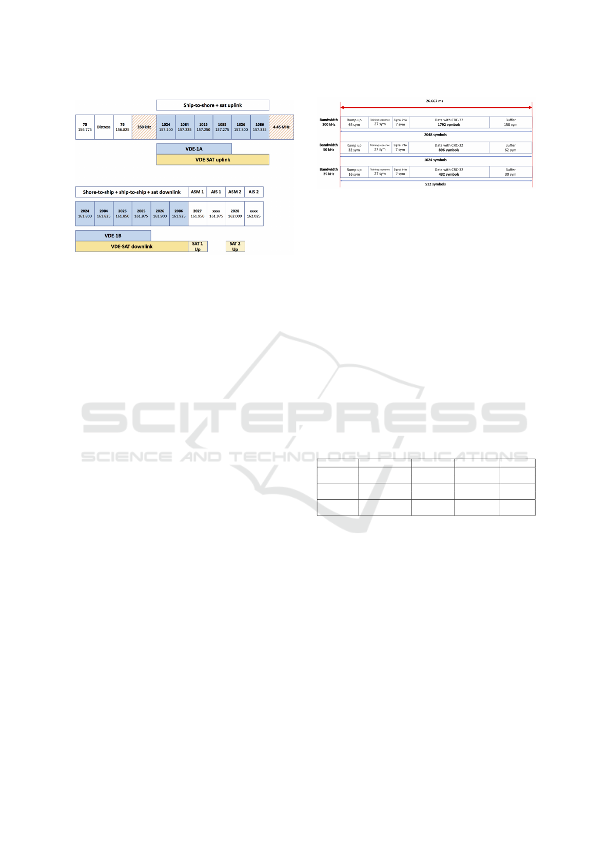
Figure 2: VDES transmission channels.
All the VDES components (legacy AIS, ASM,
VDE-SAT and VDE-TER) leverage a common frame
structure, which has a duration of 60 seconds and con-
sisting of 2250 slots. A time slot is a time interval of
approximately 26.667 ms. An Hexslot is a group of 6
consecutive time slots (duration = 160 ms). An Uber-
slot is a group of five Hexslot (duration = 800 ms). A
subframe is a group of 15 Uberslot (duration = 12 s).
Then, a frame is composed of 5 subframe. The basic
frequency allocation plan respects the following rules
to guarantee interoperability:
– 4 channels (1024, 1084, 1025 and 1085) shared
for ship-to-shore and ship-to-satellite services;
– 2 channels (1026 and 1086) exclusively reserved
for ship-to-satellite communications;
– 4 channels (2024, 2084, 2025 and 2085) shared
between shore-to-ship, ship-to-ship and satellite-
to-ship services;
– 2 channels (2026 and 2086) are exclusively reser-
ved for satellite-to-ship communications.
It is important to highlight that the range of fre-
quencies for VDE-TER and VDE-SAT is overlap-
ping, so that specific mechanisms for VDES termi-
nal to use either terrestrial or satellite slots must be
defined. The coordination between the VDE terres-
trial (ship-to-shore) and VDE-SAT uplink is achieved
using Terrestrial bulletin board (TBB) and Announ-
cement signalling channels (ASC).
4.2 VDES Burst Formats
The VDE-TER allows to alternatively use 25 kHz, 50
kHz or 100 kHz channels. The burst format varies de-
pending on the channel bandwidth as shown in Figure
3.
The data field carried on each burst consists of
multiple variable-length datagrams composed in turn
Figure 3: Burst format.
of the following fields: Datagram Type, Datagram
Size, Destination (optional), Transaction ID (Optio-
nal), Datagram Sequence Number (for multi-segment
datagrams), Source ID, Datagram Payload (variable
size), Data padding and a 4-bytes CRC.
In each of above channels, three different Modu-
lation and Coding Schemes (MCS) are applicable:
– MCS-1. Modulation = QPSK, Coding Rate = 1/2,
communication distance = 50 NM.
– MCS-3. Modulation = 8-PSK, Coding Rate = 3/4,
communication distance = 35 NM.
– MCS-5. Modulation = 16-QAM, Coding Rate =
3/4, communication distance = 50 NM.
VDE-SAT uses 50 kHz channels only. VDE-
SAT downlink supports three different Physical Layer
frame (PL-Frame) formats spread over 90 VDE slots,
as summarized in the Table 1.
Table 1: VDE-SAT downlink formats.
Format Usage Modulation Coding Rate Duration
PL-Frame 1
Bulletin
BPSK 1/2 90 slots
Board
PL-Frame 2
Multicast, ACK
QPSK 1/4 90 slots
Announcements
PL-Frame 3
File segment
8PSK 1/2 90 slots
transfer
VDE-SAT downlink can efficiently support multi-
cast of multi-packet data formats and shore originated
unicast data transfer via satellite. VDE-SAT uplink
provides the following types of functionalities:
– Two-way communications; this includes:
•
Shore initiated information polling from ships;
•
Ship initiated inquiry for information from
shore;
•
Ship initiated data transfer to shore
– Transmit Only. Collection of information from
transmit-only VDES terminals. This can be either
event-driven or periodic. The time slot and fre-
quency band for this service should be assigned
by the bulletin board and announcement signal-
ling channels.
Table 2 reports the characteristics of the five PL-
Frame formats defined for the satellite uplink.
DCNET 2018 - International Conference on Data Communication Networking
70
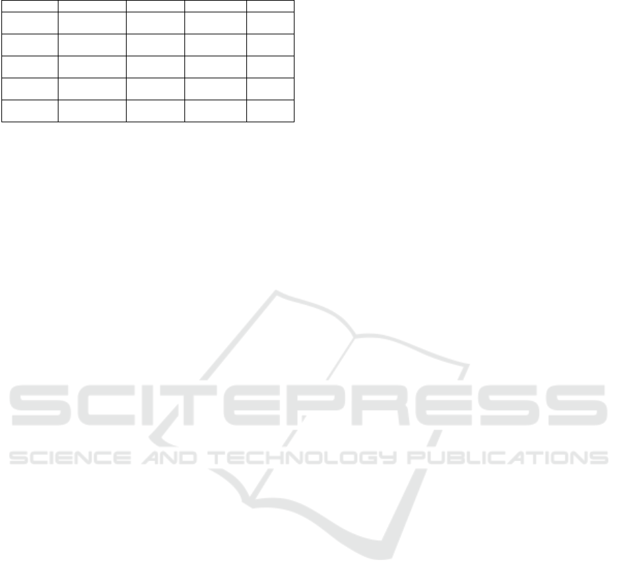
Table 2: VDE-SAT uplink formats.
Format Usage Modulation Coding Rate Duration
PL-Frame 1
ACK and short
QPSK 1/3 5 slots
messages
PL-Frame 2
ACK and short
CMP/QPSK 1/3 5 slots
messages
PL-Frame 3
ACK and short
OQPSK 3/4 1 slot
messages
PL-Frame 4
ACK and short
16APSK 3/4 1 slot
messages
PL-Frame 5
Long packet
16APSK 3/4 30 slots
file transfer
4.3 VDES Shared Medium Access
Access schemes used in the VHF maritime communi-
cations are defined in (ITU, 2014). Different TDMA-
based techniques are available in VDES to access
VHF channels in accordance to both the information
type and update timing requirements.
VDES defines three modes of operations. The first
is named “autonomous and continuous” where VDES
stations must determine their own schedule for trans-
mission, resolve scheduling conflicts with other sta-
tions. The second mode is the “assignement” one,
allowing transmission by the reception of an explicit
allocation message. Last, the “polled” mode is based
on sending an response replying to an interrogation
message. Operations in the polled mode do not con-
flict with operation in the other two modes, because
the response is expected on the channel where the in-
terrogation message was received. In order to support
the above operation modes, VDES comprises five dif-
ferent access schemes.
4.3.1 SOTDMA
The Self-Organized Time-Division Multiple Access
(SOTDMA) is the basic access scheme for AIS and
can be used for VDE messages. Suitable for perio-
dic transmissions (i.e. AIS-like), it allows to embed
in the transmitted data also the indication of the Sta-
tion ID and slot selected for the subsequent frames.
This makes possible for receiving stations to build up
a “map” of which slots are in use in the current and
in subsequent slots, supporting autonomous and con-
tinuous operations.
4.3.2 RATDMA
The Random Access Time-Division Multiple Access
(RATDMA) is suitable for sporadic (i.e. event-driven)
short messages. RATDMA is used when a station
needs to allocate a slot, which has not been pre-
announced. This is generally done for the first trans-
mission slot during data link network entry, or for
messages of a non-repeatable type. A VDES station
randomly selects a slot among the unused ones, and
it assumes that such message can collide with other
transmissions.
4.3.3 ITDMA
The Incremental Access Time-Division Multiple
Access (ITDMA) is not used as a stand-alone access
scheme but in combination with others (usually with
SOTDMA). It is useful when there is a temporary
change in the reporting period or to announce a not
periodic message. In other words, ITDMA allows a
station to pre-announce transmission slots for a non-
repeatable message (autonomous and continuous ope-
ration). A station can begin its ITDMA transmission
by either substituting a SOTDMA allocated slot or, by
allocating a new, unannounced slot, using RATDMA.
Either ways, this becomes the first ITDMA slot.
4.3.4 FATDMA
The Fixed Assignment Time-Division Multiple Access
(FATDMA) is applicable for base stations on shore,
for instance to support AtoN services. FATDMA allo-
cated slots are used for repetitive messages delivery,
assuming a pre-allocation of channels configured at
the installation of the VDES terminals; FATDMA sta-
tions broadcast a Data Link Management message to
advice other stations about FATDMA allocation.
4.3.5 CSTDMA
The Carrier Sensing Time-Division Multiple Access
(CSTDMA) is suitable for low-cost transceivers, fully
interoperable with SOTDMA (priority is given to
SOTDMA). Only a slot per frame can be allocated
with this scheme. Using this access method requires
no strict synchronization (which in fact is granted by
GPS units for the previous access mechanisms associ-
ated to Class A devices) but rather on timing derived
by ongoing transmissions by other stations. This re-
duces the complexity of the station, while requiring
to implement a “Listen before transmit” mechanism,
limiting the number of bytes that can be transmitted
in a slot.
5 PRELIMINARY ASSESSMENT
OF VDES PERFORMANCE
On the basis of all configurations and methods presen-
ted in section 4, it is possible to perform a preliminary
performance assessment of VDES based communica-
tion. Three application-oriented Key Performance In-
dicators (KPIs) were evaluated: nominal bit rate, i.e.,
VDES Performance Evaluation for Future e-navigation Services
71
the physical throughput that can be achieved (inclu-
ding overhead); user bit rate, which is the throughput
as experienced by the application; Data per frame,
which indicates the actual number of bytes that an ap-
plication can send over a single frame.
These KPIs are necessary both to properly design
the application and to identify the most suitable burst
format and transmission channels for the target ap-
plications. In addition to that, the access mechanism
shall be considered as well, in accordance to the ap-
plication requirements in terms of reliability, and pe-
riodicity. Possible combinations are proposed in the
following analysis as well.
Table 3 proposes the KPI values when consi-
dering VDE-TER downlink channels (VDE-1B) for
shore-to-ship communications. Either SOTDMA or
FATDMA can be used as access schemes and they
present identical values. In fact, shore station can be
assumed as a source of periodic updates (multicast or
unicast) towards the vessels.
Table 3: VDE-1B SOTDMA/FATDMA performance.
Burst Channel Nominal bit User bit Date per
format bandwidth rate (kbit/s) rate (kbit/s) frame (Bytes)
MCS-1
25 kHz 38.4 16.2 54
50 kHz 76.8 33.6 112
100 kHz 153.6 67.2 224
MCS-3
25 kHz 57.6 36.5 121
50 kHz 115.2 75.6 252
100 kHz 230.4 151.2 504
MCS-5
25 kHz 76.8 48.6 162
50 kHz 153.6 100.8 336
100 kHz 307.2 201.6 672
In the VDE-TER uplink, a high variability in both
size and time of sent messages can be assumed. In
case of large file transfer, ITDMA allows a better effi-
ciency because the use of up to 5 slots per frame. On
the other hand, ITDMA needs to pre-announce first
the request of slots. Consequently, actual data trans-
mission is affected by an “access delay” higher than
60 s (frame duration). Corresponding values are re-
ported in Table 4.
Table 4: VDE-1A ITDMA performance.
Burst Channel Nominal bit User bit Date per
format bandwidth rate (kbit/s) rate (kbit/s) frame (Bytes)
MCS-1
25 kHz 38.4 16.2 270
50 kHz 76.8 33.6 560
100 kHz 153.6 67.2 1120
MCS-3
25 kHz 57.6 36.5 605
50 kHz 115.2 75.6 1260
100 kHz 230.4 151.2 2520
MCS-5
25 kHz 76.8 48.6 810
50 kHz 153.6 100.8 1680
100 kHz 307.2 201.6 3135
In case the application data exceeds the allowed
data per frame, the overall application-level transmis-
sion is performed over consecutive frames, then ad-
ding 60 s time contribution per extra frame in the
message delivery time. To opposite, small sporadic
messages (i.e. requests messages, reception acknow-
ledgement, etc.) can leverage RATDMA. This latter
reduces the access delay, while presenting a collision
probability. In this case the KPIs are identical to those
presented for SOTDMA/FATDMA (Table 3). As an
alternative to RATDMA for small sporadic messages
also CSTDMA can be taken into consideration, for
low-cost receivers.
As far as the VDE-SAT downlink is concerned,
the KPIs are reported in Table 5. Similarly to the ter-
restrial component, SOTDMA and FATDMA are the
eligible access schemes.
Table 5: VDE-SAT downlink SOTDMA/FATDMA perfor-
mance.
Burst Channel Nominal bit User bit Date per
format bandwidth rate (kbit/s) rate (kbit/s) frame (Bytes)
PL-Frame 1 50 kHz 3.7 2.1 560
PL-Frame 2 50 kHz 34.1 9.6 2560
PL-Frame 3 50 kHz 51.2 28.8 7681
In the satellite uplink, the number of accessible
slots per frame is constrained by the PL-frame defi-
nition. Therefore, without loss of generality we can
refer to an ITDMA scheme as a representative of all
the other schemes. Table 6 reports the corresponding
performance. It is evident that the number of bytes
hosted in a single frame is much lower than in the do-
wnlink.
Table 6: VDE-SAT ITDMA/RATDMA performance.
Burst Channel Nominal bit User bit Date per
format bandwidth rate (kbit/s) rate (kbit/s) frame (Bytes)
PL-Frame 1 50 kHz 38.4 1.6 27
PL-Frame 2 50 kHz 76.8 1.6 27
PL-Frame 3 50 kHz 67.2 50.4 168
PL-Frame 4 50 kHz 134.4 100.8 336
PL-Frame 5 50 kHz 134.4 100.8 336
6 SIMULATION
Ad-hoc simulations are executed using the Matlab
software with the aim to characterize the models of
MARVELOWS applications over VDES. In particu-
lar, VDES channel structures have been implemented
giving the flexibility in selecting the channel band-
width (i.e. 25 kHz, 50 kHz and 100 kHz), the burst
format and the access scheme. Only VDE-TER chan-
nels have been considered. In the simulation models,
the traffic generation model allows the specification
of the message size (or of a probability distribution
of message sizes) and the message transmission sche-
duling. Mobility models was not implemented (i.e.,
ships entering and exiting the coverage area), because
for the proposed initial assessment the total number
of active ships in a given instant is sufficient.
DCNET 2018 - International Conference on Data Communication Networking
72
We set up two different simulation scenarios: i)
transmission of short periodic messages, representa-
tive of applications falling in the proposed Towage
service, where periodic notification are expected; ii)
the transmission of larger objects associated to future
data-intensive applications, such as those related to
the Dematerialisation. For the first category of ser-
vice, it is considered of paramount importance to eva-
luate the overall load of the system and the maximum
number of users able to successfully transmit short
messages without losses. Here, the assumption is that
messages fill a single slot and then data delivery is
entirely performed within the current frame if no con-
gestion occurs. For the second category of service,
instead, data transmission can require multiple slots
and then can span over consecutive frames depending
on the message size, the maximum number of slots
eligible per frame and the number of simultaneous
transmissions. In this second case, an autonomous
and continuous operational mode with different sized
messages sent in parallel by multiple VDES terminals
is assumed.
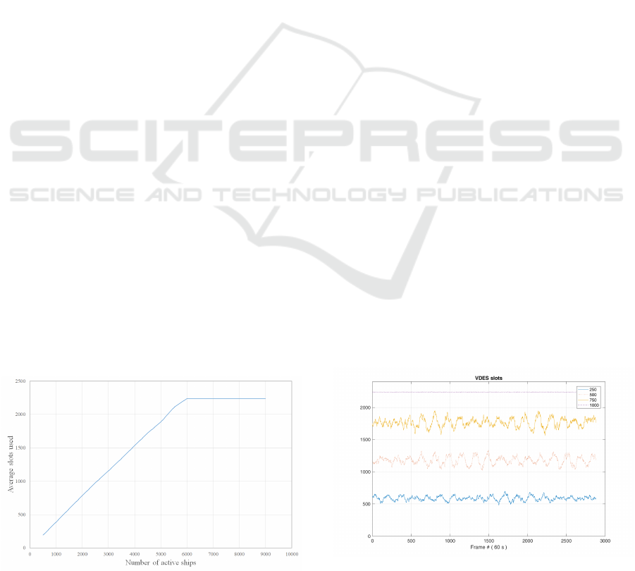
6.1 Simulation Results
The first test envisages a terrestrial 25 kHz channel for
SOTDMA ship-to-shore communications. The fre-
quency of these messages are assumed in the range
of 1 – 6 min, while the number of active ships is in-
creased from 500 to 9000 during the simulation.
Simulation output records the average number of
slots occupied by the transmissions over the 2250
available. The results are shown in figure 4: with
growing number of active ships, the average num-
ber of busy slots increases with a linear trend, unless
the limit of slots is reached (i.e., at 2250 slots) when
about 6000 ships are active. Nonetheless, when ap-
proaching (and exceeding) this saturation limit, the
number of eligible slots for transmission is reduced,
so that the competition lead to an additional access
delay and messages loss, due to collisions of the ini-
Figure 4: Simulation of AIS messages channel occupation.
tial RATDMA access. It is important to highlight that
such service can co-exist with AIS legacy transmissi-
ons, alleviating the AIS channels by delivering addi-
tional information on the new VDE channels. Furt-
hermore, VDES data channels can leverage satellite
transmissions, to completely overcome VHF terres-
trial ranges limits of 10–20 NM. In this way, VDES
opens the way to a completely new classes of applica-
tions and overcome limitations of present AIS based
services.
Concerning the second test, a VDE-TER channel
is used to allow transmission of large data messages,
i.e. associated to images, navigation-related publica-
tions or chart updates related to the Dematerialization
service. The goal of the test is to identify the sy-
stem limit in sending relatively large-amounts of data,
when the number of active ships increases. The follo-
wing setup is considered:
– 250, 500, 750 or 1000 active terminals;
– message size is 250 Kbytes, which represents for
instance the size of a good quality compressed
image;
– each active ship transmits the message each 1 to 2
hours as sporadic guaranteed messages using ter-
restrial 100 KHz channel and MCS5;
– simulation duration of 2 days;
The first result presented is the evolution of slots
occupation over time, shown in figure 5 for the dif-
ferent amount of active ships. Due to the necessity
of delivering data without contention, a SOTDMA
access scheme was enabled during these tests. The
average number of slots occupied for transmission is
577, 1157, 1732 and 2179 when the number of active
terminals goes from 250 to 1000 in steps of 250. The
system shows a moderate load for up to 750 terminals,
with a practical saturation of slots measured when the
terminals are 1000.
When there is a large availability of slots (which in
practice is experienced up to 750 terminals), the mes-
Figure 5: Slots used for VDE transmission as function of
time.
VDES Performance Evaluation for Future e-navigation Services
73
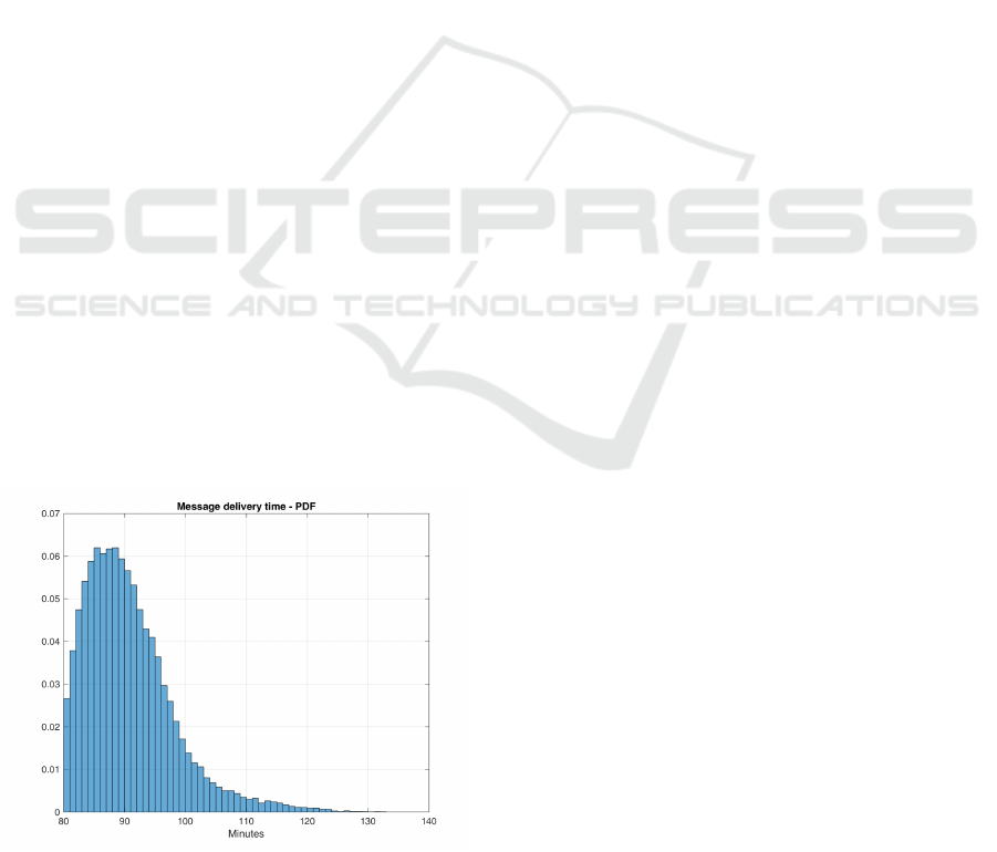
sage transmission time is predictable and solely due
to the access to the channel and the channel bitrate.
In this situation, the messages delivery time is 80 mi-
nutes in average. On the contrary, when the number of
active terminals is 1000, the effect of the access me-
chanism (SOTDMA)results into an average delivery
time of 90.42 minutes. In this case, the experienced
delay in average is similar to the average transmis-
sion intervals defined for the test (i.e., 90 minutes).
In fact, if looking at figure 6, where the probability
distribution function of the message full reception is
reported (for all messages generated during the simu-
lation), it is possible to verify that few objects are for
sure delivered exceeding the 120 minutes. This means
that, according to the application transmission period
(which was defined within 1 hour to 2 hours), some
data objects can be ready for the transmission while
the transmission of the previous one is not yet com-
pleted: this can create problems to the application it-
self.
The modeling of the MARVELOWS applications,
allowed to identify the target performance as function
of the number of active terminals (expected into a gi-
ven coverage area) and the channels in use. These as-
pects shall be carefully considered for the definition
of future e-navigations systems. For instance, the ex-
pected maximum and average time for the delivery of
a data object must be taken into account in designing
the application, so that transmission periods and data
sizes are carefully tailored to avoid communication
overlaps.
As support for future applications definition, the
combined use of satellite channels for VDES will pro-
vide a significant help, since some service can be mi-
grated on satellite frequencies which offer wider co-
verage (e.g., not limited to the VHF terrestrial co-
verage of 10–20 NM) and may be less congested by
Figure 6: Probability Density Function of messages deli-
very times in saturation conditions (message load exceeding
100%, 1000 terminals).
the lack of legacy communications. This aspect will
be addressed in future work, improving the simulation
models and scenarios considered.
7 CONCLUSIONS
This paper proposes a detailed characterization of the
upcoming VDES technology with the aim to provide
a preliminary assessment of supported performance.
VDES significantly improves on traditional AIS, by
introducing additional channels and transmission me-
chanisms. Therefore, higher data rates and more re-
sources foster the definition of new maritime data ex-
change applications. We proposed two possible ad-
vanced services leveraging VDES: Towage and De-
materialisation. The former represents a sort of en-
hancement of traditional AIS dealing with short mes-
sages, while the latter aims to extend data exchan-
ges to larger messages. In this regard, VDES of-
fers a good flexibility in configuring the service allo-
wing different channel bandwidths, burst formats and
access schemes. Nevertheless, the definition of new
maritime services requires a fine-tuning and tailoring
to the VDES link layer characteristics. In fact, appli-
cation requirements need to meet timing and format
constraints imposed by the standards. Simulation re-
sults provide a clear indication on such limits in terms
of maximum number of served terminals and message
delivery times. Awareness on such performance fra-
mework is deemed of paramount importance in the
definition of future services, when the satellite com-
ponent will become available and will increase the
overall system capacity and service coverage out of
the coastal areas.
REFERENCES
ESA (2013-2018). European Space Agency, European-
based SAT-AIS system. https://artes.esa.int/sat-ais.
ESA (2017). Maritime applications exploiting reliable VHF
data exchange low-cost system (MARVELOWS) Pro-
ject. https://business.esa.int/projects/marvelows.
IMO (2001). Guidelines For The Onboard Operational Use
Of Shipborne Automatic Identification Systems (AIS).
A.917(22).
ITU (2009). Characteristics of VHF radio systems and
equipment for the exchange of data and electronic
mail in the maritime mobile service RR. ITU-R,
M.1842.
ITU (2012). Assignment And Use Of Maritime Mobile Ser-
vice Identities. ITU-R, M.585-6.
ITU (2014). Technical characteristics for an automa-
tic identification system using time division multiple
DCNET 2018 - International Conference on Data Communication Networking
74

access in the VHF maritime mobile frequency band.
ITU-R, M.1371-5.
ITU (2015). Technical characteristics for a VHF data
exchange system in the VHF maritime mobile band-
width. ITU-R, M.2092.
The Nautical Institute (2015). Definition of the future vhf
data exchange system for maritime. Introduction to
the VDES.
VDES Performance Evaluation for Future e-navigation Services
75
