
A Chain Topology for Efficient Monitoring of Food Grain Storage using
Smart Sensors
Alekha Kumar Mishra
1
, Asis Kumar Tripathy
1
, Mohammad S. Obaidat
2, ∗
, Zhiyuan Tan
3
,
Mukesh Prasad
4
, Balqies Sadoun
5
and Deepak Puthal
4
1
Vellore Institute of Technology, Vellore, India
2
ECE Department, Nazarbayev University, Astana, Kazakhstan
2
KASIT, University of Jordan, Jordan
3
Edinburgh Napier University, U.K.
4
University of Technology Sydney, Australia
5
Al Balqa’ Applied University, Jordan
Keywords:
Food Grain Storage Monitoring, Smart Sensor Devices, Sensor Networks, Network Topology, Chain
Topology.
Abstract:
Due to lack of an efficient monitoring system to periodically record environmental parameters for food grain
storage, a huge loss of food grains in storage is reported every year in many developing countries, especially
south-Asian countries. Although Smart Sensor Networks have been successfully implemented in various ap-
plications such as health-care, military, and wildlife monitoring, there are still various issues to be addressed
in food grain storage monitoring applications. Due to the food grain storage infrastructure constraints, the
commonly practiced network topologies of sensor devices such as mesh, star, and grid cannot provide an ef-
fective monitoring environment. In this paper, we proposed a topology using smart sensors that can effectively
cover and monitor the food grain storage area. It uses a chained structure of sensor devices with directional
antennas to accurately sense and report the environmental data. The proposed topology works better than
common topologies due to its chain-based structure which remains unaffected by various hindrance imposed
due to food grain storage infrastructure. From the experimental results it is conclude that the proposed topol-
ogy has effective coverage percentage, detection accuracy, and message delivery over Cluster-based and Mesh
topologies in food grain storage environments.
1 INTRODUCTION
Due to climatic changes, irregularities were observed
in weather conditions in recent years. These changes
directly affect the longevity and utility period of food
grains. It is reported that the wheat and rice produc-
tion is passing the record level every year in south-
Asian countries. However, due to lack of adequate
monitoring infrastructure and process, the loss of
food grains in these years apprehend the productiv-
ity (Manay and M.Shadaksharaswamy, 2008; Sawant
et al., 2012). Irregular changes in weather condi-
tions provides favorable conditions for growth of in-
sect, pests, molds, rodents, fungi, and mycotoxins in
food grain storage. It is reported that around twenty
percent of food grains are wasted in food storage.
∗
Fellow of IEEE and Fellow of SCS
The above fact demands a monitoring and control
environment for food grain in food depot across the
agricultural zones of a country. In this environment,
the influential factors of the food storage depots are
continuously observed to maintain favorable scenario
for food grains. It is found that traditional or man-
ual food grain storage monitoring by store officials
is inefficient as they cannot reach to all locations on
regular basis. The smart sensor devices are playing
these years in the sensing domain these days where
these devices detect and collect relevant environmen-
tal data such as temperature, atmospheric pressure,
humidity, and light (Sahoo et al., 2012; Sharma et al.,
2017b). Securing such infrastructure is also playing
a vital role in current communication infrastructure
(Puthal et al., 2018). Therefore, a smart sensor net-
work can be effectively used for monitoring influenc-
Mishra, A., Tripathy, A., Obaidat, M., Tan, Z., Prasad, M., Sadoun, B. and Puthal, D.
A Chain Topology for Efficient Monitoring of Food Grain Storage using Smart Sensors.
DOI: 10.5220/0006850600890098
In Proceedings of the 15th International Joint Conference on e-Business and Telecommunications (ICETE 2018) - Volume 1: DCNET, ICE-B, OPTICS, SIGMAP and WINSYS, pages 89-98
ISBN: 978-989-758-319-3
Copyright © 2018 by SCITEPRESS – Science and Technology Publications, Lda. All rights reserved
89

ing parameters in food grain storage (Hadjidj et al.,
2013; Carlos-Mancilla et al., 2016). It is observed
from the literature that the smart sensor devices are
commonly deployed in free space. If more number
of smart sensors are involved for a particular monitor-
ing application, then it is found that there exists suf-
ficient free space for direct communication between
these devices. These common deployment structure
is provided by various network topologies such as
tree, mesh, grid, star, and clustered. However, these
topologies may not be suitable for food grain storage
monitoring application, since the food grain storage
are often filled with grain bins and there is hardly
a clear line of sight inside the storage area of bins.
This paper devises an effective topology of smart sen-
sors to monitor influential environmental parameters
in a food grain storage depot. It is efficient and more
suitable for this monitoring environment compared to
mesh, tree, and clustered topology. It is shown that
the proposed topology can perform effectively with
sensor devices equipped with directional antenna and
sectored sensing disc. The performance of the pro-
posed topology is compared with mesh and clustered
topology using simulation experiments and found to
be better in terms of detection accuracy, energy effi-
ciency, and message delivery ratio. The sections of
this contribution are organized in the following way.
Section 2 provides a detailed report on infrastructure
of food grain storage depot. Section 3 summaries the
characteristics along with pros and cons of existing
smart sensor network topologies. Section 4 provides
an analysis on unsuitability of existing topologies for
monitoring food grain storage depot. Section 5 elab-
orates on the structure and operational details of the
proposed topology for food grain storage monitor-
ing. Section 6 analyzes the coverage and energy ef-
ficiency of the proposed topology. Section 7 summa-
rizes simulation results of comparison between pro-
posed topology and existing competing schemes fol-
lowed by concluding remarks in Section 8.
2 SURVEY OF FOOD GRAIN
STORAGE INFRASTRUCTURE
Almost a common standard is followed throughout
the globe for constructing infrastructure for food grain
storage depot. The dimension and facilities may vary
up to some extent depending on the kind of food
grain. The most common shape of storage is pyramid
dome shaped as shown in Figure 1.
The standard storage area of the depot is 126 meters
× 22 meters. The height of the depot varies from 5.5
meters to 6.25 meters. The entire capacity of the de-
Figure 1: The dimension and shape of a food grain depot.
pot is divided into 3 compartments with each com-
partment of capacity 5000 metric ton (MT). The num-
ber of stacks for each compartment is twelve. The
ventilators are used on both top and bottom side of the
walls. The stack size is approximately 6 meters × 10
meters. The Galvanized Iron Corrugated (GIC) silos
storage are used for longterm storage in selected de-
pots where food grain may be stored for a longer pe-
riod (years). GIC silos are quite expensive compared
to standard storage depot (Deshpande et al., 2010).
Additionally, cover and plinth (CAP) storage struc-
tures are the most common among the farmers. Some-
times, cover and plinth structures are also practiced by
food grain depot officials to store excess amount of
food grains with depot’s premise. Sufficient space are
provided between food grain stacks inside a depot to
facilitate smooth movement of carriage vehicles. But,
during post-harvesting months the food grain depots
are often full occupied with food grain bins.
The essential parameters that are monitored regularly
in the food grain depot is temperature and air flow
inside depot, and moisture content of the food grains.
Table 1 shows the drying temperature and maximum
moisture level maintained for different types of food
grains (Hellevang, 2010).
Table 1: Moisture content levels and drying temperature for
various food grains.
Food grain Drying Max. Moisture
Temperature (
◦
C) Content (%)
Paddy 60 17
Wheat 65 14.5
Oats 60 14
Barley 55 14.8
Maize 49 14
Flax 80 10
Peas 45 16
It is reported that these parameters are continuously
monitored and when these parameters reaches a level
beyond the mentioned range due to changes in envi-
ronment, it requires the manual attention of the food
ICE-B 2018 - International Conference on e-Business
90

grain store officials for further action. Smart sensors
are a suitable options to replace the manual monitor-
ing process. A set of smart sensor devices may be de-
ployed to form a smart network to facilitate the mon-
itoring process. In the following section, a survey of
existing smart network topology is provided for food
grain storage monitoring.
3 SURVEY OF SMART SENSOR
NETWORK TOPOLOGY
It has always been a challenging task to plan a suit-
able network topology for a target application. It is
required that the designed network topology must sat-
isfy the desired coverage, connectivity, coverage, and
network lifetime (Fan and Jin, 2010). The topolo-
gies as reported in the literature are mostly designed
based on the target application requirements (Ceclio
and Furtado, 2014). A brief survey of these topolo-
gies is provided below.
Star topology is a single-hop system, where all sen-
sors communicate directly to the gateway. This is
simple and efficient for small networks (Yang et al.,
2017). Here, a single node failure is not an issue since
it does not affect the communication process of other
nodes. There can be more network segments branch-
ing out from the central gateway node. The energy
consumption for communication is limited to the dis-
tance between a node and its gateway. This topology
is suitable for network of smaller size limited to ge-
ographical area of approximately 100 meters. When
it is required to be deployed in large scale, the star
topology is applied with hierarchical schemes. In a
tree topology, the sink node also known as base sta-
tion (BS) is considered as the root of the network tree.
The root node is connected with relay nodes; those
are responsible for forwarding sensed data to the root.
The relaying nodes forms the network with multiple
levels with root as sink node (Sharma et al., 2017a).
Sometime the relay nodes are equipped with sensors
in order to perform both sensing and relaying task.
The tree topology can be scalable to desired size with
a minimum effort. The overall energy consumption of
the network is lower because of the small range node-
to-node communication. The data transmission from
sensing nodes to the sink node requires the coordina-
tion of intermediate relaying nodes. A mesh topol-
ogy mostly resembles a mathematical graph struc-
ture, where each node is in connection with all other
nodes located with its communication range. An ef-
ficient multi-hop communication scheme is essential
for this topology. Since, intermediate nodes in the
path to sink node play the role of forwarding node,
it is necessary to ensure that the path to sink node is
connected before sending data. Mesh topology based
networks are excellent for fault tolerance due to ex-
istence of multiple path to sink nodes. The charac-
teristics of existing multi-hop communication scheme
can be easily modified to support larger network. In
a Grid topology, the network is divided into a rectan-
gular grid, where sensor devices are deployed at each
grid point(Roy et al., 2018). The commonly adapted
grid layout are unit square, equilateral triangle, and
hexagon. The square grid topology is more popu-
lar compared to its counterparts due to having natu-
ral placement characteristics. A grid topology is an
ideal condition of topology in terms of coverage of
network. Since, it is really difficult to achieve opti-
mal performance with basic grid topology, often more
than one node are placed on a square grid. Clus-
tered topology is most adaptive and energy-efficient
for most common applications. As it is named, the
topology consists of a number of clusters, where each
cluster comprises a group of nodes located geograph-
ically closer to each other. A designated node called
cluster-head (CH) is responsible for coordination of
nodes within a cluster and forwarding data of the
nodes to the sink node. The task of non-CH nodes is
limited to sensing and sending data to CH. There may
be bridge to connect CHs and facilitate inter-cluster
communication. The bridge nodes significantly re-
duce the energy consumption of inter-cluster com-
munications. The clustered topology has the lowest
communication overhead among all topologies due
to minimum number of message communications per
round. Moreover, hierarchical structure simplifies the
process of routing messages.
Some applications demand the combination of more
than one previously discussed topologies to improve
the performance (Aziz et al., 2013). The hybrid ap-
proaches are scalable up to thousands of nodes with-
out deteriorating the network operations. Clustered-
tree topology forms tree among the clusters in the
network (Hong et al., 2016). It uses multilevel het-
erogeneous features to define network structure. It
takes the hierarchical structure advantage from tree,
and utilizes optimal network communication scheme
of clusters. Cluster-star topology is a hybrid of star
and clustered topology. It uses the simplified structure
of star topology at the lower end of the network while
utilizing cluster based communication at the higher
level. Cluster-mesh topology divides the deployment
area into number of cells. Here, the term cells is re-
ferred to rectangular areas of equal size (Alsemairi
and Younis, 2016). Each cell forms a cluster among
the nodes in the cell. Thereafter, an inter-CH mesh
network is formed for inter-cluster communication.
A Chain Topology for Efficient Monitoring of Food Grain Storage using Smart Sensors
91

The sink node participates in the topology as a cluster
head and does not appear just as the end point of data
routes. Table 2 summaries the strengths and limita-
tions of the above discussed topologies.
4 ANALYSIS OF EXISTING
TOPOLOGIES FOR FOOD
GRAIN STORAGE
MONITORING
The first and foremost requirement of a food grain
storage structure is that network deployment must not
utilize the open space available within the depot. It
is reported that placing sensing devices in this space
would hinder the process of bulk loading and unload-
ing of food grains. Secondly, the sensing devices
cannot be deployed near the food grain bins as the
bins stacks are displaced frequently from one place to
another depending upon the space requirements. In
this case, devices deployment locations are required
to change every time; the bins are relocated or dis-
placed. Moreover, sensing devices placed in these lo-
cations may be prone to physical damage. Finally,
there is no additional support such as pillars near the
food grain bins to fix sensing devices permanently.
Based on the above requirements and constraints it is
found that the only option available to deploy the net-
work is to utilize the inner walls and ceiling of the
depot. The topology like star, tree, mesh, grid, and
clusters cannot be used efficiently in food grain depot.
This is because, all the above mentioned topologies
and the hybrids requires the deployment of the nodes
in the region of interest. Additionally, these topolo-
gies need open space between nodes for communica-
tion in all direction because of the omni-directional
antenna equipped with these devices. The star topol-
ogy is feasible up to some extent; however, it is dif-
ficult to find a suitable location for gateway node to
stay in the communication range of all the devices.
All clustered topologies require the sensing devices
to be deployed near the food grains, therefore are not
suitable for food grain storage. The grid topology is
suitable for food grain depot if the grid is deployed on
the inner walls. However, the sensing range may be
limited due to omni-directional antenna. Moreover it
requires significantly more number of sensor devices.
The tree based topology may also require significantly
large number of nodes when deployed on the inner
walls of the depot. Table 3 summarizes the unsuit-
ability of existing topologies for food grain storage
monitoring. It is observed from the above discussion
that the sensing devices with directional antenna and
sectored sensing disc are more suitable for indoor ap-
plications compared to their counterparts (Yu et al.,
2011).
5 PROPOSED WORK
In this section, the proposed topology of smart sensor
devices is presented for efficiently monitoring food
grain storages. This topology is a double ended chain
structure and it is named as two-tail chain topology.
It consists of smart sensors that form a chain structure
with the following additional features. The node de-
ployed on the top of the chain is the head node also
known as the gateway node. It is responsible for col-
lecting data from all nodes and forwarding it to the
relaying node of the network. An additional relaying
node is connected to the gateway node. It is respon-
sible for forwarding the data collected from gateway
node to the sink node. It is assumed that the relaying
node can communicate to sink node either directly or
via multi-hop communication. The sensing devices
are equipped with directional communication antenna
and sensors with sectored sensing disc. Each node in
the network can sense and communicate data except
gateway and relaying node. The process of sending
sensed data begins from both ends (also known as
tails) of the chain. It is then forwarded to the next
node toward the location of gateway in the chain until
it reaches gateway node. In the following subsections,
the structure and functions of proposed topology is
discussed in details.
5.1 Structural Details of Proposed
Topology
Figure 2 shows the deployment structure of the pro-
posed topology. Two nodes at the end of the chain
are called tail nodes. The tail nodes and the gateway
nodes are placed at the opposite ends across the length
of the storage depot. The inner walls across the length
of the storage depot are used to deploy the chain of
sensing devices. The simplest structure of the chain
consists of only one chain on each of the walls. More
than one chain can be deployed on each wall and ceil-
ing connecting to gateway depending on the coverage
requirements.
The above topology of sensing devices is effec-
tive only if the following type of device positioning
structure is followed. Figure 3 shows the direction of
communicating radio antenna of sensing devices in
the chain. Since the major task of these devices is to
sense temperature and moisture data and send them to
gateway node, the communicating sector range of the
ICE-B 2018 - International Conference on e-Business
92
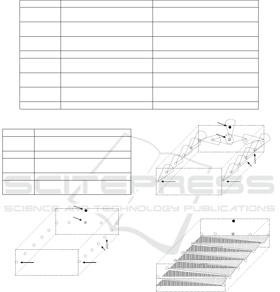
Table 2: Summary of pros and cons of smart sensor network topologies.
Topology Strengths Limitations
Star Overall lower power consumption Limited communication
Small area network (100 meters)
Tree Lower power consumption Nodes are time synchronized
Scalable Requires coordination among the nodes
Mesh Fault tolerant Redundancy
Scalable Higher energy consumption
Grid Ideal condition for coverage Not practical
Cluster Minimized no. of messages Cluster-head selection overhead
Simplified routing
Cluster-Tree Lower power consumption Computational overheads
Improved network lifetime
Cluster-Star Lower energy Additional hardwares
Scalable
Cluster-Mesh Lower energy Higher node density
Table 3: Unsuitability of smart sensor network topologies.
Topology The reason for unsuitability
Star Difficulty in positioning the gateway
node
Tree Requires open space
Mesh Requires significantly higher num-
ber of nodes
Grid Limited sensing range
Cluster Requires open space for inter-
cluster communication
head node
Relaying node
Tail node
6 meters
126 meters
22 meters
Tail node
sensing nodes
Figure 2: The position of sensing devices in the chained
structure.
directional antenna are positioned towards the upper
level (gateway end) of the chain.
Figure 4 shows the sensing rage of the devices.
Since devices with sectored sensors have long range
sensing ability compared to omni-directional sensors,
the sensing discs are positioned facing the opposite
wall of the depot to achieve accurate sensing from the
mid area of the depot.
head node
sensing nodes
Relaying node
Tail node
22 meters
Tail node
Figure 3: Communication range of sensors with directional
antenna.
126 meters
22 meters
6 meters
Figure 4: Sensing range of the sensors.
5.2 Energy Efficient Data Aggregation
Here, it is assumed that the sensing devices are time
synchronized for data collection and aggregation pro-
cess. The data collection begins at tail nodes. In each
round of data collection, tail nodes send data to the
next node towards gateway in the chain. The interme-
diate nodes in the chain aggregate the received data
from tail end with its own data and forward them to
A Chain Topology for Efficient Monitoring of Food Grain Storage using Smart Sensors
93

the next node towards gateway. Algorithm 1 shows
this process of aggregation. The node in the commu-
nication range of gateway can directly send the data
to gateway.
Algorithm 1: Algorithm for OnReceive().
OnReceive(Message *msg){
prev node ←− msg.sender
data
prev
←− msg.data
data
new
←−Aggregate(data
prev
, data
sensed
)
msg.status[prev node] ←− 1
msg.data ←− data
new
msg.sender ←− id
sel f
send(msg)
}
5.3 Communication Between Relaying
Node and Sink Node
Upon receiving the aggregated data from both ends
of the chain, gateway node sends it to the relaying
node. The number of relaying nodes in the network
depends on the number of food grain depots under
the processing of monitoring. The following existing
topologies can be adapted depending on the location
of sink and number of relaying nodes:
• Star topology: If it is possible to locate the sink
node around the mid point of the area of the food
grain depot center, then star topology would be
more suitable for this part of the communication.
In this case, all relaying nodes can directly com-
municate with the sink node. Thus, the process
of forwarding aggregated data by a relaying node
is independent of other relaying nodes in the net-
work.
• Tree topology: When all relaying nodes are not
in the communication range of the sink node and
number of relaying nodes is large, then it is appro-
priate to use tree topology of relaying nodes with
sink node as root. A simple multi-level routing
scheme (Zin et al., 2014; Tanwar et al., 2015) can
be used to forward the aggregated data to the sink
node using this topology.
5.4 Communication Under Node
Failure
To synchronize the process of the data aggregation,
each node waits for a specific period of time before
initiating its data transfer. When the data arrives from
the tail end before the timer expires, then the node
follows the normal aggregation and forwards process
as discussed before. However, if the data does not
arrives before the timer expires, then node initiates a
fresh data transfer along with a failure status bit for
the previous node in the chain. Algorithm 2 repre-
sents this communication process.
Algorithm 2: Algorithm for OnTimerExpire().
OnTimerExpire(){
msg = createMessage()
msg.data ←− data
sensed
msg.status[id→predecessor()] ←− 0
msg.sender ←− id
sel f
send(msg)
}
Failure of a node leads to a break of a link in the
chain; only if each node has exactly one node in its
communication range. The tolerance of connectiv-
ity can be improved by increasing the node coverage
across the chain to greater than or equal to 2. This im-
plies that the connectivity failure tolerance is directly
proportional to the node density across the chain.
6 ANALYSIS
6.1 Network Size and Coverage
The proposed two-tail chain topology can collect data
efficiently with minimum number of nodes compared
to existing topologies. This is possible due to the
chain structure of sensor devices, and positioning of
their directional sensing disc. Since devices also
uses directional antenna for communication and po-
sitioned across the line of the chain, the proposed
topology is able to provide a clear space for commu-
nication. Whereas, the topologies such as mesh, tree,
and cluster-based find it difficult to get a clear range
of communication in the food depot with minimum
number of nodes. Here, an analysis of the proposed
topology is provided to establish a relationship be-
tween network size and required coverage. The sens-
ing range of sensing devices lies between 25-30 me-
ters (Ammari and Das, 2012). The width of standard
depot is approximately 22 meters. Therefore, a sensor
deployed on either walls can sense the area in its sec-
tored disc range till the opposite wall. The depot can
be divided by sensing zone of each sensor as shown
in Figure 5. It can be observed that by placing sens-
ing devices at the center of the sensing disc (shown
by dark spots) in the figure, the entire depot can be
covered.
Consider a depot of dimension l ×b m
2
. Let r and
θ are the sensing range and angle of sensing sector for
ICE-B 2018 - International Conference on e-Business
94
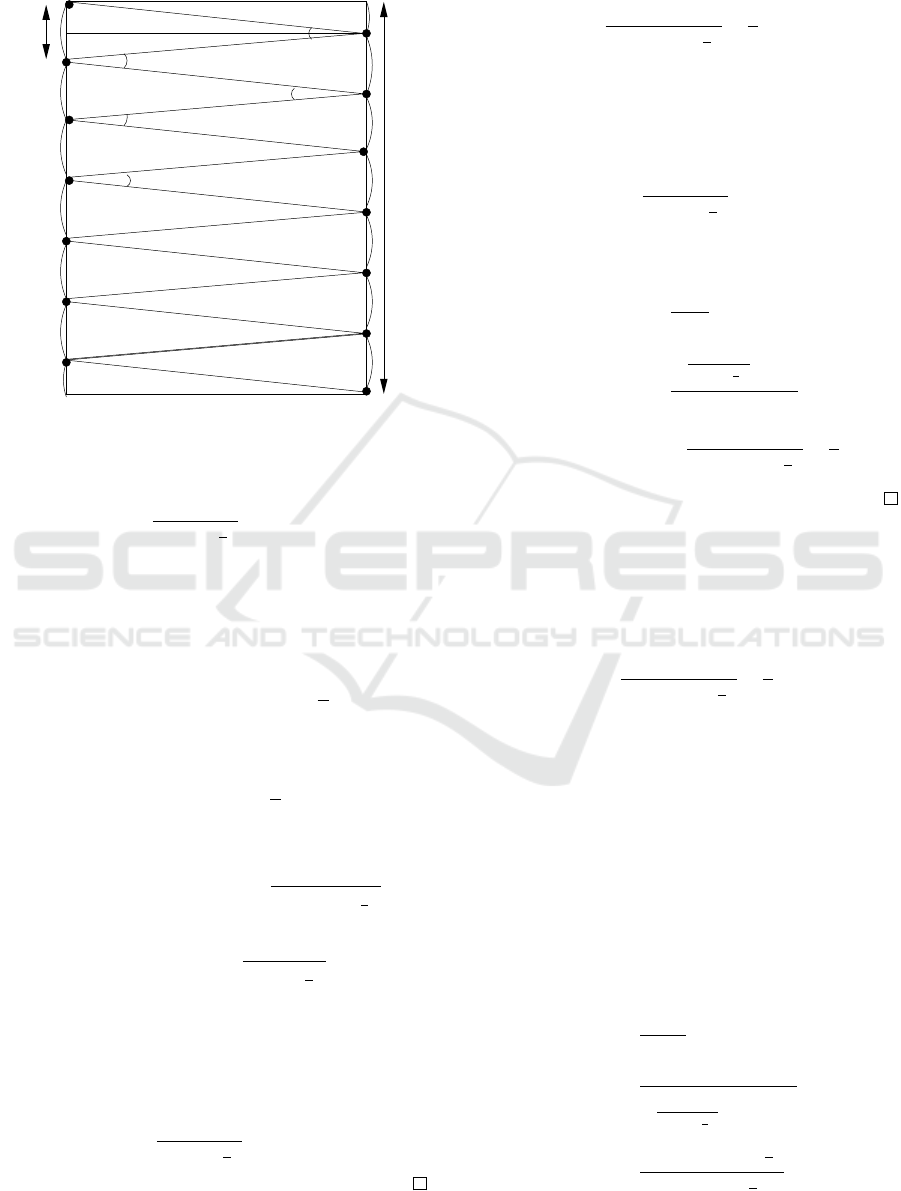
a sensor respectively. Let d be the length of the chord
as shown in Figure 5.
θ
θ
θ
l
d
r
r
r
Figure 5: Coverage of depot using sectored sensing disc.
Theorem 1: The number of nodes required by two-
tail chain topology to achieve 1-coverage is:
l
r × sin
θ
2
+ 2
!
. (1)
Proof. From Figure 5, it can be inferred that the total
number of sectors required to cover depot of dimen-
sion l × b is the sum of number of sectors facing left
wall and number of sectors facing right walls plus 2
additional partial sectors at both ends of the depot.
No. of sectors in depot = 2 ×
l
d
+ 2 (2)
The value of d can be represented in terms of r and
angle θ as:
d = 2 × r × sin
θ
2
(3)
Using Equation 3 in 2 we get:
No. of sectors in depot = 2 ×
l
2 × r × sin
θ
2
+ 2
=
l
r × sin
θ
2
+ 2
(4)
From the above Equation, 1-coverage of the depot can
be achieved by placing a sensor at each center of the
sectors as shown by dark spot in Figure 5. There-
fore, number of nodes required to achieve 1-coverage
is equal to:
l
r × sin
θ
2
+ 2
!
(5)
Theorem 2: Chain density for 1-coverage topol-
ogy is equal to:
1
2 × r × sin
θ
2
+
1
l
!
. (6)
Proof. Considering Figure 5, the dimension of the de-
pot is given by l × b. Then, the total length of the
chain across the wall is 2 × l. Using Equation 5, the
number of nodes required for 1-coverage is given by:
N =
l
r × sin
θ
2
+ 2
!
. (7)
Therefore, the chain density to achieve 1-coverage is
given by:
chain density =
N
2 × l
=
l
r×sin
(
θ
2
)
+ 2
2 × l
=
1
2 × r × sin
θ
2
+
1
l
!
. (8)
k-coverage of depot is achieved by increasing
chain density for 1-coverage topology by a factor of
k.
Lemma 1: Chain density for k-coverage topology is
equal to:
k ×
1
2 × r × sin
θ
2
+
1
l
!
. (9)
6.2 Energy Consumption
This paper follow energy consumption model pro-
vided in (Mishra and Samantara, 2016), which is con-
sidered for evaluating energy consumption of sensing
devices used in proposed topology. Let us assume
that the size of data message is m bits. To achieve
1-coverage the number of nodes required by two-tail
topology is given by Equation 5. Since the chain
length is taken as 2 × l, then the average distance be-
tween two successive sensing devices in the chain is
given by:
d =
2 × l
N − 1
=
2 × l
l
r×sin
(
θ
2
)
+ 2
− 1
=
2 × l × r × sin
θ
2
l + r × sin
θ
2
(10)
A Chain Topology for Efficient Monitoring of Food Grain Storage using Smart Sensors
95
The total energy consumed by all devices in the chain
in a single round of data transmission is given by:
E = E
T X
+ E
RX
+ E
A
(11)
where, E
T X
, E
RX
, and E
A
are the total energy con-
sumed during data transmission, reception, and aggre-
gation respectively. The energy consumed to transmit
a message of m bit over a distance of d is given by:
E
elec
× m + ε
amp
× m × d
2
(12)
where, E
elec
and ε
amp
is the energy required to trans-
mit a single bit by the transmitter electronics and the
amplifier respectively. Then, E
T X
is given by:
E
T X
= (E
elec
× m + ε
amp
× m × d
2
) × N
=
E
elec
× m + ε
amp
× m × d
2
×
l
r × sin
θ
2
+ 2
!
Similarly, E
RX
is given by
E
RX
= (E
elec
× m ×
l
r × sin
θ
2
+ 2
!
(13)
Let E
ag
be the energy spent for aggregation of m-bit
data, then
E
A
= E
ag
×
l
r × sin
θ
2
+ 2
!
(14)
7 EXPERIMENTAL RESULTS
The performance of the proposed two-tail chain topol-
ogy is evaluated by simulation analysis. The param-
eters of interest are temperature and moisture content
(Hu, 2013). Both of these values are varied using
physical process module. The proposed topology is
compared with mesh and clustered topology using the
following metrics: detection accuracy, message deliv-
ery ratio, energy consumption, delay, and number of
alive nodes in the network.
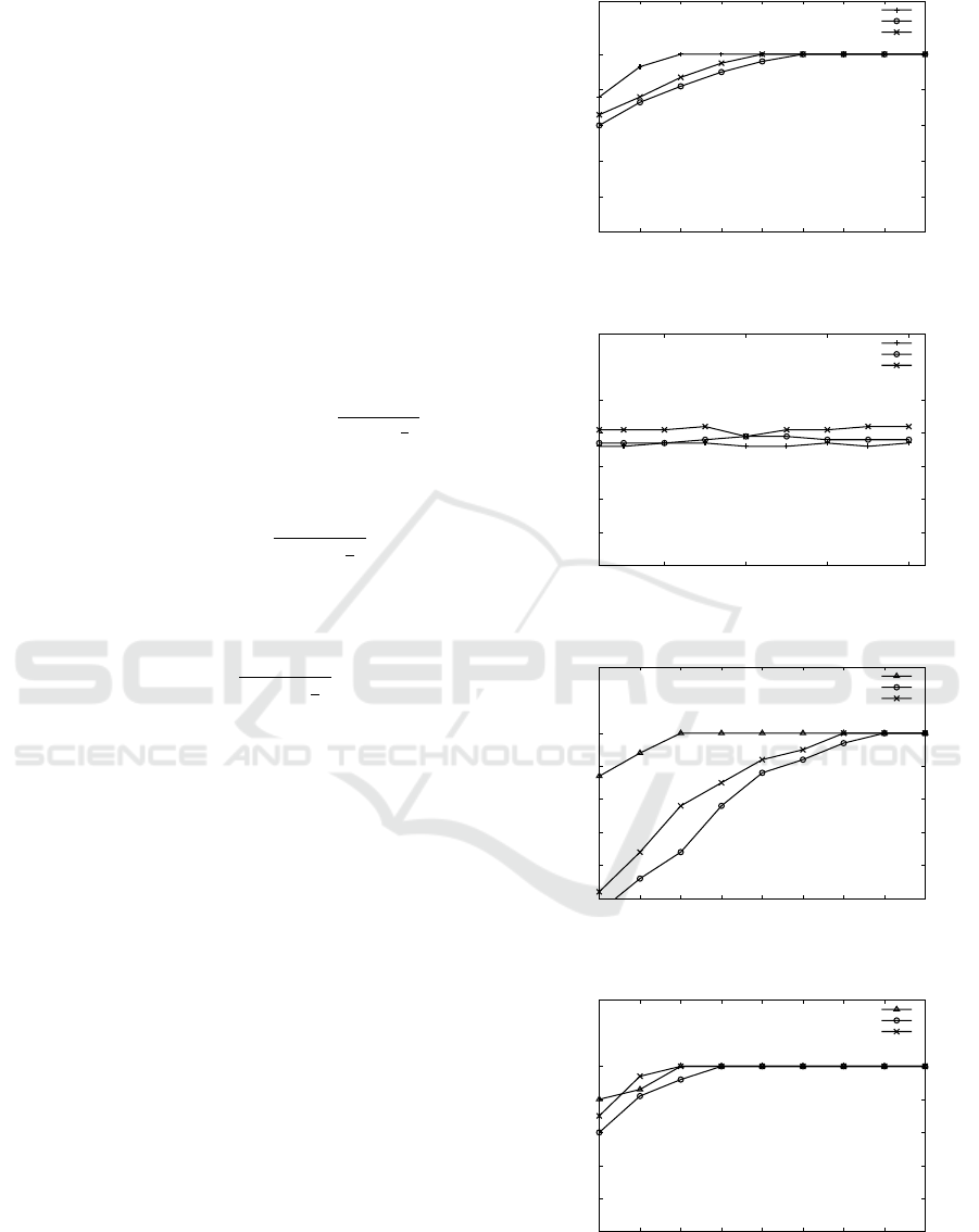
The plot for detection accuracy vs. number of
nodes deployed in the network is depicted in Figure
6. It is observed that the detection accuracy of pro-
posed topology raise to hundred percent when number
of nodes is greater than or equal to twenty. This accu-
racy is better than the existing ones. This is because
of optimal positioning of sensing devices to sense data
uniformly over the food grain storage depot.
The comparison of energy consumption over
number of rounds is shown in Figure 7. It is ob-
served from the figure that the energy consumption
per node of the proposed topology over number of
rounds remains almost constant. A marginally lesser
20
40
60
80
100
10 15 20 25 30 35 40 45 50
Detection Accuracy(in %)
Number of nodes deployed
Proposed
Mesh
Cluster-based
Figure 6: Detection Accuracy vs. Number of nodes de-
ployed in the chain
0.1
0.2
0.3
0.4
0.5
50 100 150 200
Average Energy Cosumed per node (mJ)
Rounds
Proposed
Mesh
Cluster-based
Figure 7: Energy Consumed per node vs. Number of
rounds.
50
60
70
80
90
100
10 15 20 25 30 35 40 45 50
Message Delivery Ratio(in %)
Number of nodes deployed
Proposed
Cluster-based
Mesh
Figure 8: Message delivery ratio with food grain bins inside
the depot.
50
60
70
80
90
100
10 15 20 25 30 35 40 45 50
Message Delivery Ratio(in %)
Number of nodes deployed
Proposed
Cluster-based
Mesh
Figure 9: Message delivery ratio without food grain bins
inside the depot.
ICE-B 2018 - International Conference on e-Business
96
consumption is achieved compared to mesh and clus-
tered topology due to use of directional antenna for
communication.
Figures 8 and 9 show the comparison of mes-
sage delivery ratio over number of nodes deployed in
the network with and without foog grain bins inside
the depot, respectively. For the proposed topology,
the message delivery ratio is computed with relaying
node as the destination node. It is observed that the
proposed topology is able to achieve higher message
delivery ratio with food grain bins in the depot than
mesh and cluster-based topology. This is because,
when food grains are placed in the depot, they hinder
the communication between the nodes of mesh and
clustered topology. However, two-tail chain topology
uses routing of messages along the chain and remains
unaffected by existence of food grain bins in the de-
pot.
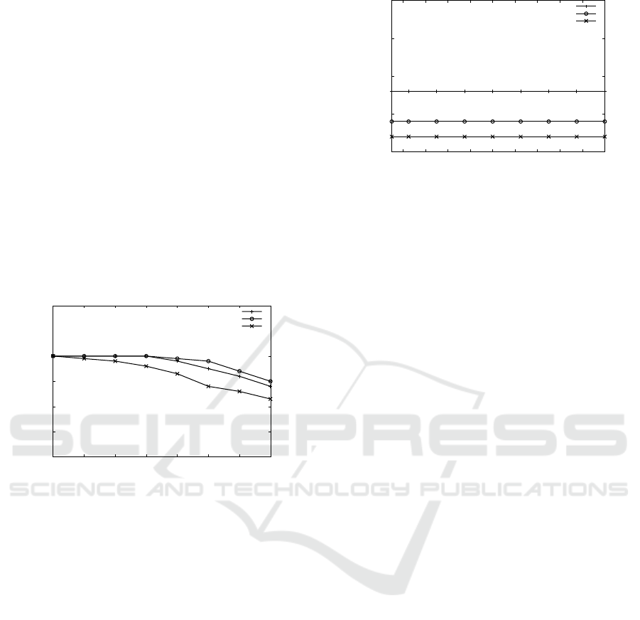
10
20
30
40
50
1800 1900 2000 2100 2200 2300 2400 2500
Number of Alive Nodes
Rounds
Proposed
Mesh
Cluster-based
Figure 10: Number of alive nodes vs. Number of rounds.
Figure 10 compares the number of alive nodes in
the network vs. number of rounds. It is observed that
the rate of decreasing in the number of alive nodes
in proposed topology is marginally higher than mesh
topology and lower than clustered topology. This is
because, the proposed topology does not use multi-
path routing like mesh topology to balance the re-
maining energy of the nodes. The higher rate of de-
crease in the clustered topology is due to significant
consumption of energy for inter-CH communication
inside food grain depot.
Finally, the comparison of average delay vs. num-
ber of rounds are depicted in the Figure 11. It is ob-
served that the proposed topology incurs higher delay
compared to mesh and clustered topology and it re-
mains almost constant over number of rounds. This
delay is mostly due to additional waiting time of each
node before processing and forwarding the data to the
next node.
400
450
500
550
600
20 40 60 80 100 120 140 160 180 200
Average Delay per Node(msec)
Rounds
Proposed
Mesh
Cluster-based
Figure 11: Average delay per node vs. Number of rounds.
8 CONCLUSION
The proposed two-tail chain topology aims to provide
an efficient monitoring process for food grain depot.
The proposed topology is designed based on the stan-
dard infrastructure of food grain depots and other en-
vironmental constraints. Due to open space constraint
the proposed topology use a chain structure to deploy
sensing devices on the inner walls of the depot. To
achieve efficient sensing and communication in this
environment, the sensing devices are equipped with
directional communication antenna instead of omni-
directional antenna. This helps to achieve a clear line
of sight for sensing and communicating data inside
the food grain depot. The performance of the pro-
posed topology is compared with that for mesh and
clustered topology. The results of detection accuracy,
message delivery ratio, and energy consumption in-
fers the suitability of the proposed topology over ex-
isting ones for monitoring food grains.
Further, we are aiming to deploy proposed two-tail
chain topology in real-time testbed for better evalua-
tion our topology.
ACKNOWLEDGEMENTS
An initial short version of this work has been pub-
lished in the proceedings of 5th International Con-
ference on Advanced Computing, Networking, and
Informatics (ICACNI), June 2017 (Tripathy et al.,
2017).
REFERENCES
Alsemairi, S. and Younis, M. (2016). Forming a Cluster-
Mesh Topology to Boost Base-Station Anonymity in
Wireless Sensor Networks. In Proceedings of IEEE
A Chain Topology for Efficient Monitoring of Food Grain Storage using Smart Sensors
97

Wireless Communications and Networking Confer-
ence, WCNC 2016, pages 01 – 06.
Ammari, H. M. and Das, S. K. (2012). Centralized and
Clustered k-Coverage Protocols for Wireless Sensor
Networks. IEEE Transactions on Computers, 61(1).
Aziz, A. A., Sekercioglu, Y. A., Fitzpatrick, P., and
Ivanovich, M. (2013). A Survey on Distributed Topol-
ogy Control Techniques for Extending the Lifetime of
Battery Powered Wireless Sensor Networks. IEEE
Communications Surveys & Tutorials, 15(1):121 –
144.
Carlos-Mancilla, M., Lpez-Mellado, E., and Siller, M.
(2016). Wireless Sensor Networks Formation: Ap-
proaches and Techniques. Journal of Sensors,
2016(2016):1 – 18.
Ceclio, J. and Furtado, P. (2014). Wireless Sensors in Het-
erogeneous Networked Systems, chapter Wireless Sen-
sor Networks: Concepts and Components, pages 5 –
25. Springer.
Deshpande, N., Shaligram, A. D., Botre, B. A., Bindal, S.,
and Sadistap, S. . (2010). Embedded E-nose Appli-
cation to Sense the Food Grain Storage Condition. In
Proceedings of International Conference of Compu-
tational Intelligence and Communication Networks,
pages 608 – 611.
Fan, G. J. and Jin, S. (2010). Coverage Problem in Wire-
less Sensor Network: A Survey. Journal of Networks,
5(9):1033 – 1040.
Hadjidj, A., Souil, M., Bouabdallah, A., Challal, Y., and
Owen, H. (2013). Wireless sensor networks for re-
habilitation applications: Challenges and opportuni-
ties. Journal of Network and Computer Applications,
36(1):01 – 15.
Hellevang, K. J. (2010). Grain drying. NDSU Extension
Service, Fargo, ND (1994).
Hong, Z., Wang, R., and Li, X. (2016). A Clustering-
tree Topology Control Based on the Energy Fore-
cast for Heterogeneous Wireless Sensor Networks.
68 IEEE/CAA JOURNAL OF AUTOMATICA SINICA,
3(1):68 – 77.
Hu, F. (2013). Tele-Healthcare Computing and Engineer-
ing: Principles and Design , chapter Hardware: Sen-
sor Mote Architecture and Design. SCIENCE PUB-
LISHERS, CRC Press.
Manay, N. and M.Shadaksharaswamy (2008). Foods Facts
and Principles. New Age International, 3rd edition.
Mishra, A. K. and Samantara, M. K. (2016). A dynamic
energy-efficient chain formation scheme for PEGA-
SIS in wireless sensor networks. In Proceedings of
2nd International Conference on Computational In-
telligence & Networks, CINE 2016, pages 41 – 46.
Puthal, D., Malik, N., Mohanty, S. P., Kougianos, E., and
Yang, C. (2018). The blockchain as a decentralized se-
curity framework. IEEE Consumer Electronics Mag-
azine, 7(2):18–21.
Roy, S. S., Puthal, D., Sharma, S., Mohanty, S. P., and
Zomaya, A. Y. (2018). Building a sustainable internet
of things: Energy-efficient routing using low-power
sensors will meet the need. IEEE Consumer Electron-
ics Magazine, 7(2):42–49.
Sahoo, B., Rath, S., and Puthal, D. (2012). Energy efficient
protocols for wireless sensor networks: A survey and
approach. International Journal of Computer Appli-
cations, 44(18):43–48.
Sawant, A., Patil, S. C., Kalse, S. B., and Thakor, N. J.
(2012). Effect of temperature, relative humidity and
moisture content on germination percentage of wheat
stored in different storage structures. AgricEngInt:
CIGR Journal, 14(2):01 – 14.
Sharma, S., Puthal, D., Jena, S. K., Zomaya, A. Y., and
Ranjan, R. (2017a). Rendezvous based routing pro-
tocol for wireless sensor networks with mobile sink.
The Journal of Supercomputing, 73(3):1168–1188.
Sharma, S., Puthal, D., Tazeen, S., Prasad, M., and Zomaya,
A. Y. (2017b). Msgr: A mode-switched grid-based
sustainable routing protocol for wireless sensor net-
works. IEEE Access, 5:19864–19875.
Tanwar, S., Kumar, N., and Rodrigues, J. J. (2015). A
systematic review on heterogeneous routing protocols
for wireless sensor network. Journal of Network and
Computer Applications, 53(0):39 – 56.
Tripathy, A. K., kumar Mishra, A., Kumar, A., and Das,
T. (2017). A Two-Tailed Chain Topology in Wire-
less Sensor Networks for Efficient Monitoring of
Food Grain Storage. In Proceedings of 5th Interna-
tional Conference on Advanced Computing, Network-
ing, and Informatics (ICACNI).
Yang, C., Puthal, D., Mohanty, S. P., and Kougianos, E.
(2017). Big-sensing-data curation for the cloud is
coming: A promise of scalable cloud-data-center mit-
igation for next-generation iot and wireless sensor
networks. IEEE Consumer Electronics Magazine,
6(4):48–56.
Yu, Z., Teng, J., Bai, X., Xuan, D., and Jia, W. (2011). Con-
nected coverage in wireless networks with directional
antennas. In Proceedings of IEEE INFOCOM, pages
2264–2272.
Zin, S. M., Anuar, N. B., Kiah, M. L. M., and Pathan,
A.-S. K. (2014). Routing protocol design for se-
cure WSN: Review and open research issues. Journal
of Network and Computer Applications, 41(0):517 –
530.
ICE-B 2018 - International Conference on e-Business
98
