
LightByte: Communicating Wirelessly with an Underwater Robot
using Light
Robert Codd-Downey and Michael Jenkin
Department of Electrical Engineering and Computer Science, York University, Toronto, Ontario, Canada
Keywords:
Robot Communication, Underwater Robotics, LiFi.
Abstract:
Communication with and control of underwater autonomous vehicles is complicated by the nature of the water
medium which absorbs radio waves over short distances and which introduces severe limitations on the band-
width of sound-based technologies. Given the limitations of acoustic and radio frequency (RF) communication
underwater, light-based communication has also been used. Light-based communication is also emerging as
an effective strategy for terrestrial communication. Can the emerging Light Fidelity (Li-Fi) communication
standard be exploited underwater to enable devices in close proximity to communicate by light? This paper
describes the development of the LightByte Li-Fi model for underwater use and experimental evaluation of its
performance both terrestrially and underwater.
1 INTRODUCTION
Very few robots are designed to operate completely
autonomously. Rather their actions are controlled
(or at least influenced) by commands provided to
them by human operators. Leaving aside the com-
plexity of the development of a language for human-
robot communication, the actual problem of transmit-
ting electrical information in air is a relatively simple
task using modern technologies such as WIFI (IEEE,
2013), Bluetooth (IEEE, 2002), NFC(ISO, 2013) and
RFID(ISO, 2008). Unfortunately such approaches
find limited application in the underwater environ-
ment because the electro-magnetic spectral bands as-
sociated with these technologies are highly attenu-
ated in the underwater domain rendering them unus-
able at any reasonable distance(Bogie, 1972). This is
not to say that RF-based communication is not pos-
sible underwater. Radio wave attenuation in water is
highly dependent upon frequency, and thus underwa-
ter communication technology is typically based on
very low frequency (VLF) radio waves in the 3-30kHz
range. Such signals can propagate long distances but
have particularly poor bandwidth. Given the short-
comings of RF transmission underwater, other tech-
niques are more popular. One effective approach is
to use acoustic communication. Sound propagates
more effectively underwater than in air. Underwa-
ter acoustic communication was developed for the US
Navy during the 1940’s(Quazi and Konrad, 1982) in
the form of the underwater telephone. Since then the
technology has matured with commercial off the shelf
(COTS) acoustic underwater acoustic modems being
readily available(EvoLogics, 2009). Such devices
are manufactured for different depth/distance appli-
cations, but performance in the 31.2kbit/s over a 1km
range are typical. Given the long ranges associated
with VLF and acoustic techniques, other approaches
are more appropriate over shorter distances. One in-
teresting approach here is to utilize visible spectrum
light communication. Such devices can be developed
with a range of different power/distance/bandwidth
tradeoffs and can be constructed using relatively inex-
pensive off the shelf components. Furthermore, given
the commercial interest in light-based communication
terrestrially, one can expect a substantive decrease in
component costs as the technology is deployed in the
terrestrial domain. Given this, here we consider the
questions: How effective can light fidelity (Li-Fi)-
based technology be underwater, and is it practical to
develop ”Li-Fi modems” for robot-robot and robot-
human communication underwater?
Although Li-Fi can certainly be used to develop
a network-based communication infrastructure, here
we are particularly interested in bidirectional com-
munication between two underwater units; an au-
tonomous underwater device and an underwater de-
vice controlled by a human operator. Although the
human could certainly be underwater themselves,
we concentrate on the case in which a shore- or
Codd-Downey, R. and Jenkin, M.
LightByte: Communicating Wirelessly with an Underwater Robot using Light.
DOI: 10.5220/0006855202990306
In Proceedings of the 15th International Conference on Informatics in Control, Automation and Robotics (ICINCO 2018) - Volume 2, pages 299-306
ISBN: 978-989-758-321-6
Copyright © 2018 by SCITEPRESS – Science and Technology Publications, Lda. All rights reser ved
299
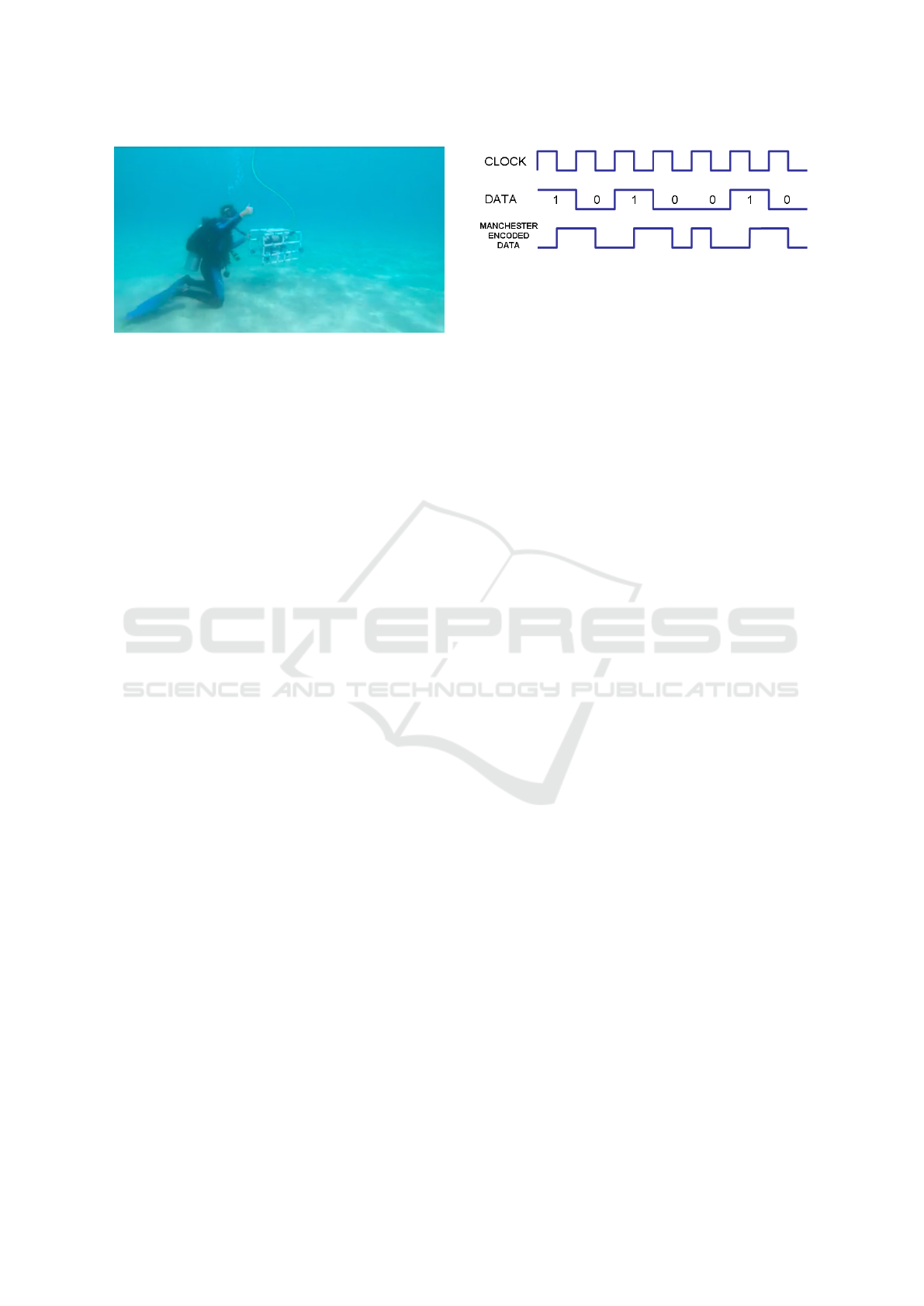
Figure 1: Unmanned underwater vehicle control. Commu-
nicating with such a device wirelessly is complicated by
the nature of the aquatic medium. As a consequence wired
communication is common with its inherent problems re-
lated to cable management and fouling.
boat-based operator communicates via light with
a single thruster-based UUV such as the Milton
platform(Codd-Downey et al., 2017) shown in Fig. 1.
2 BACKGROUND
Underwater communication has a long history and
can be traced back at least to Leonardo da Vinci who
observed ”If you cause your ship to stop, and place
the head of a long tube in the water, and place the
other extremity to your ear you will hear ships at a
great distance from you”(da Vinci, 2010). Of course,
there have been substantive technological improve-
ments since then. Lack of space prohibits a full re-
view of advances in the use of sound, radio waves
and light energy for communication underwater here.
The interested reader is directed to(Kaushal and Kad-
doum, 2016) for a recent review of the RF, acoustic
and optical communication strategies underwater and
their limitations.
Although RF and acoustic communication strate-
gies have their advantages, we are particularly inter-
ested in short range, reasonably-high bandwidth com-
munication for which optical approaches seem partic-
ularly useful. A number of such systems have been
developed and deployed underwater using both laser
and LED-based systems. Although high-power sys-
tems are necessary for long distance communications,
for shorter distance (<10m) communication, a wide
range of technologies exist that can be applied to the
problem. Terrestrially, digital communication over
short ranges has also received substantive attention
and standard communication technologies have been
developed using RF technologies including Blue-
tooth, WIFI and other technologies. Light-Fidelity
communication (Li-Fi) (Condliffe, 2011) aims to use
visible light as the communication medium for digital
Figure 2: Manchester Encoding.
communication (See (Haas et al., 2016) for a review
of the technology.) Although still in its infancy, Li-Fi
has shown substantive promise, however, there have
been few large-field tests of the technology.
Beyond the terrestrial domain there have also been
a number of efforts to deploy Li-Fi technology under-
water. For example, (Medhekar et al., 2016) looks at
the transmission properties of different light sources
for Li-Fi underwater and observes that LED-based
communication has advantages when line of sight
cannot be guaranteed. (Wang et al., 2016) demon-
strates a long distance (100m) light-based communi-
cation system that utilizes optics to concentrate the
emitter and a single photon avalanche diode to en-
hance detection.
The IEEE 802.15.7 standard for visible light com-
munication (VLC)(Rajagopal et al., 2012) utilizes on-
off keying (OOK) to encode the format of the data
stream from the transmitter to the receiver. The basic
idea here being that by turning a light on and off at
the transmitter the receiver can decode this sequence
into the transmitted message. A popular approach
for this OOK process is Manchester encoding (Tanen-
baum and Wetherall, 2011) (Fig. 2), which is a recom-
mended OOK approach in the IEEE VLC standard.
Essentially this approach modulates the data stream
using a clock signal. One downside of this mecha-
nism is its relatively high overhead in terms of the
communication signal consuming 100% more band-
width than a raw encoding scheme.
3 UNDERWATER LI-FI MODEM
Evaluating the potential for the use of VLC for UUV
control involves developing waterproof modems that
modulate an electronic signal onto the light signal
and then back again to an electronic signal. Rather
than developing a system that simulates this process
above ground (e.g., by placing a water tank between
emitter and receiver), or developing a small tank that
can be suspended from the surface, we are particu-
larly interested in testing performance under realistic
conditions where human-robot interaction will hap-
pen. That is, at depths greater than 10m and under re-
alistic turbidity and external illumination conditions.
ICINCO 2018 - 15th International Conference on Informatics in Control, Automation and Robotics
300
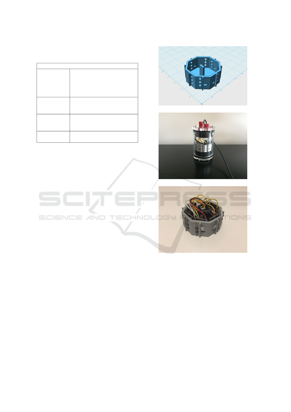
Table 1: A list of the primary components that make up
each transceiver. For the purpose of brevity resistors and
transistors are excluded from this list.
Primary Components
Teensy 3.2 32bit ARM Cortex-M4 arduino-
compatible micro-controller.
The micro-controller has 256kb
program storage space, 64kb of
dynamic memory
TSL12S-LF Eight light-to-voltage convert-
ers, combines a photodiode and
transimpedance amplifier.
C503D-WAN Twenty-four cool white LEDs
with high luminous intensity
(64600 mcd).
SSD1306 An I2C OLED graphical dis-
play.
The goal here is to not only identify issues related to
Li-Fi generally, but also to investigate potential inter-
actions between underwater housing construction and
illumination conditions found at depth. This decision
drives the basic physical design of the LightByte sys-
tem shown in Fig. 3. The LightByte ”modems” are es-
sentially small cylindrical housings with port glands
for power and data (USB). Light emission and sens-
ing is performed using emitters and sensors mounted
in an octagonal 3D printed structure that is mounted
inside the housing and isolates the emitters from the
receivers to reduce crosstalk and also enables both
emitters and receivers to cover a full 360
◦
horizontal
field. Operationally, these devices can be mounted as
small external pucks on the external shell of a UUV.
Each LightByte transceiver communicates using
five sets of emitters each composed of three LEDs,
five light sensors that act as receivers and a small
amount of electronics to drive and monitor the emit-
ters and receiver. A small display is also included
within each transceiver to enable monitoring of the
state of the device when it is operating. The cost of
each unit is under $200 US including the cost of the
housing. Table 1 lists the components housed within
each transceiver node.
Each LightByte node provides a USB connection
for data transfer. For low power operations the Li-Fi
LED’s can be powered from the USB bus. For higher
power operations, power can be provided externally
or a battery can be included inside the transceiver
node.
(a)
(b)
(c)
Figure 3: LightByte Transceiver node. (a) 3D printed
mounting rig. (b) A LightByte transceiver node in its under-
water housing. (c) The electrical components of the node.
4 COMMUNICATION
PROTOCOL
The IEEE 802.15.7 standard for VLC provides stan-
dards at both the data modulation and physical lay-
ers. The IEEE standard speaks to the use of VLC
for local communication networks. As the goal here
is for point-to-point communication we deviate from
the IEEE standard at the physical layer, introducing a
simple frame-based communication structure (based
on UDP with components borrowed from TCP). The
LightByte: Communicating Wirelessly with an Underwater Robot using Light
301

two transducers are identical in structure with identi-
cal communication protocols in both directions. Fol-
lowing the IEEE 802.15.7 standard frames are en-
coded using a Manchester line code. In addition to
being an effective encoding scheme, this scheme has
the benefit of using a constant amount of power irre-
spective of the data being sent and thus the flicker of
the emitting LEDs cannot be perceived. This makes
the emitter appear as a dim stable illuminator to any
operator in the vicinity.
4.1 Physical Layer
As signals are emitted they are encoded using the
Manchester coding scheme. This requires the emit-
ter to maintain a stable clock to drive the encoding
process. All of the output LED’s are driven to the
same level (100% of their maximum possible out-
put (20 mA)). The complete set of LEDs use a total
of 480mA in addition to the 45mA consumed by the
micro-controller.
4.2 Data Link Layer
The data link layer utilizes the capabilities of the
physical layer to construct a protocol for data trans-
mission that deals with errors and regulates the flow
of data in an effective manor. This is accomplished
by encapsulating data into 128 byte fixed sized pack-
ets/frames with 8 byte headers that can be used to vali-
date, sequence and identify each piece of data. Data is
packed into a frame/packet as shown in Table 2. The
ESC, PREAMBLE, SYNC, STX and ETX symbols
are reserved. In order to avoid becoming confused by
such tokens appearing in the signal itself, these sym-
bols are reserved in the data packet and must be re-
coded there. Like UDP packets there is no guarantee
of delivery, however unlike UDP this protocol does
guarantee packet ordering. The physical layer also
provides duplicate packet protection because data is
only transmitted once and not relayed by subsequent
nodes. Data frames are of fixed sized.
4.3 Error Detection
The Data Link Layer provides the ability to per-
form a certain amount of error correction. The two-
byte Fletcher-16 (Fletcher, 1982) checksum facilitates
the identification of transmission errors in the data
stream. Frames that fail the checksum test are dis-
carded, invalidating the current data stream. Consid-
ering that frames are sent sequentially the ID, DID
and FID framing bytes can be used to identify non
sequential frames and intrusive frames from another
Table 2: Packets are 128 bytes long. The Preamble, STX,
SYNC and ETX characters are reserved in the data packet
and are escaped in the data transmission using the ESC char-
acter 0x1B.
Packet/Frame Structure
PREAMBLE (0xAA) used to compute a signal
average
SYNC (0xD5) allows the receiver to
align itself, signifies the
start of a frame
ID (1-byte) unique identifier of the
sending node
DID (1-byte) unique identifier for
the current sequence of
frames
FID (1-byte) numerical identifier for
the frame in sequence
CHKSUM (2-bytes) two-byte checksum of
the data in the frame
(Fletcher-16)
STX (0x02) signifies the start of data
transmission
DATA (119-bytes) user data
ETX (0x01) signifies the end of data
transmission
sender. Error detection helps to prevent invalid data
from being propagated further up the communication
stack. Thus, only validated transmitted and received
data is transferred to the application layer.
4.4 Data Communication
Given the ability to send bidirectional packets with
checksums a variety of different lossless bidirectional
communication strategies are possible. For ease
of implementation a modified version of the classic
ZMODEM(Forsberg, 1988) protocol is used to trans-
mit binary data between the two transceivers.
5 EVALUATION
The bottleneck of this VLC device is the response
time of the TSL12S-LF light sensor which has a re-
sponse time of approximately 10µs. This equates
to absolute maximum bit rate of approximately 6.25
kilobytes per second. Each data frame has an eight
byte overhead, which translates to a theoretical maxi-
mum of approximately 5.8 kilobytes per second. This
level of throughput is capable passing controller in-
formation akin to a wireless joystick and other low
bandwidth sensors.
ICINCO 2018 - 15th International Conference on Informatics in Control, Automation and Robotics
302
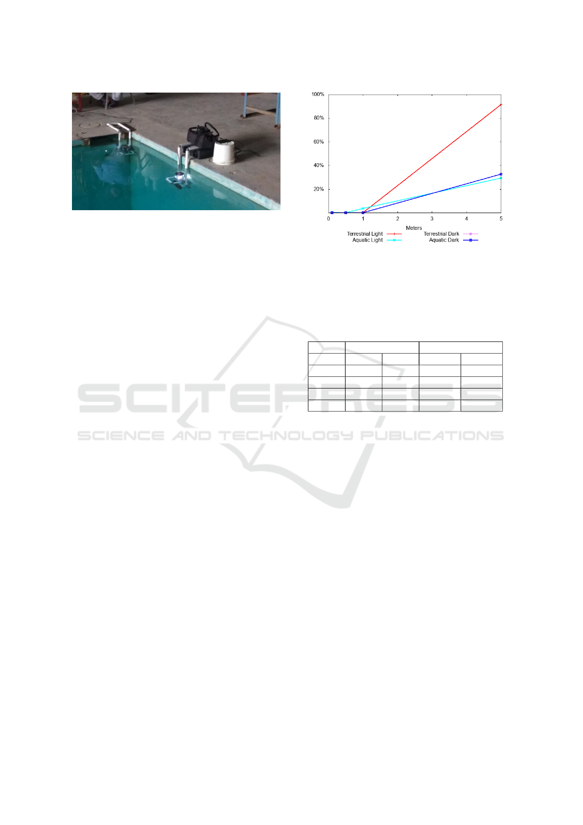
Figure 4: Aquatic Test. Both the transmitting and receiving
nodes during an aquatic range test are shown. The emitter
appears as a constant (but dim) light. Here the receiver is
not transmitting.
The experiments that follow are all conducted in a
similar manner, each consisting of a one-way commu-
nication between transmitter node and a receiver node
as shown in Fig. 4. The transmitter is configured to
send out a thousand numbered “test string” messages.
The receiver is connected to a laptop where incoming
packets are recorded and then analyzed to recover the
packet drop percentage.
5.1 Range Test
Unlike most Li-Fi systems which operate in con-
trolled environments where ambient light is a minimal
competitor, the Li-Fi modems operate in direct com-
petition with light from the sun and other intensive
artificial sources and ambient light in the surround-
ing environment. Competition becomes a problem
when the attenuation of light through the environmen-
tal medium (water or air) causes the brightness of the
transmitter to be indistinguishable from the ambient
light. In an environment with no ambient light the
maximum range of transmission is based on the at-
tenuation of light through the environmental medium
(water or air) and the light sensitivity of the receiver.
The range test experiment evaluates the opera-
tional range of the device under normal and optimal
ambient conditions in both terrestrial and aquatic en-
vironments. Both devices are setup in the same ver-
tical plane with a single opposing transmitter and re-
ceiver manually aligned at 10cm, 50cm, 1m, and 5m
apart. Results are given in Fig. 5 and Table 3. Rates
are for 1000 packets. Note that performance in air un-
der strong ambient illumination shows very high drop
off rates at 5m but that performance in the water in the
2-3m range is quite good even under strong illumina-
tion.
Figure 5: Range packet drop-off rates. The terrestrial dark
signal is occluded by the aquatic dark signal in the above
graph. Each test involved transmitting 1000 packets from
the sender to the receiver. Numerical values are given in
Table 4.
Table 3: Packet/Frame drop percentages in different envi-
ronments and lighting conditions at various distances. Rates
were estimated over 1000 packets.
Terrestrial Aquatic
Offset Light Dark Light Dark
10 cm 0.01% 0.01% 0.25% 0.00%
50 cm 0.00% 0.00% 0.00% 0.00%
1 m 0.07% 0.00% 3.70% 0.00%
5 m 91.3% 32.7% 29.40% 32.65%
5.2 Radial Offset Test
Each LightByte modem consists of eight separate
units arranged radially around the modem. A set of
three vertically aligned transmitters and one receiver
is positioned on each face of the octagonal layout.
Transmitter LEDs have a viewing angle of 15
◦
with a
sharp falloff in brightness after 22.5
◦
. Receivers have
a nominal viewing angle of ±30
◦
. These specifica-
tions suggest that at certain radial misalignments of
the transmitter and receiver the communication sig-
nal will be attenuated due to the optics of the receiver
and emission properties of the transmitting LED. Due
to the octagonal layout of the sensor, realignment
should occur every 45
◦
. However, since the trans-
mitter/receiver pair order is inverted every other emit-
ter/transmitter pair, realignment with a similar trans-
mitter/receiver pair configuration occurs every 90
◦
.
This experiment evaluates packet/frame drop per-
centage as a function of the orientation alignment of
the transmitter and receiver. Both devices are set up in
the same vertical plane with a single opposing trans-
mitter and receiver manually aligned 1m apart. One
sensor is then rotated from 0
◦
to 90
◦
in increments of
5
◦
. Results are shown in Fig. 6. As the receiver is ro-
LightByte: Communicating Wirelessly with an Underwater Robot using Light
303
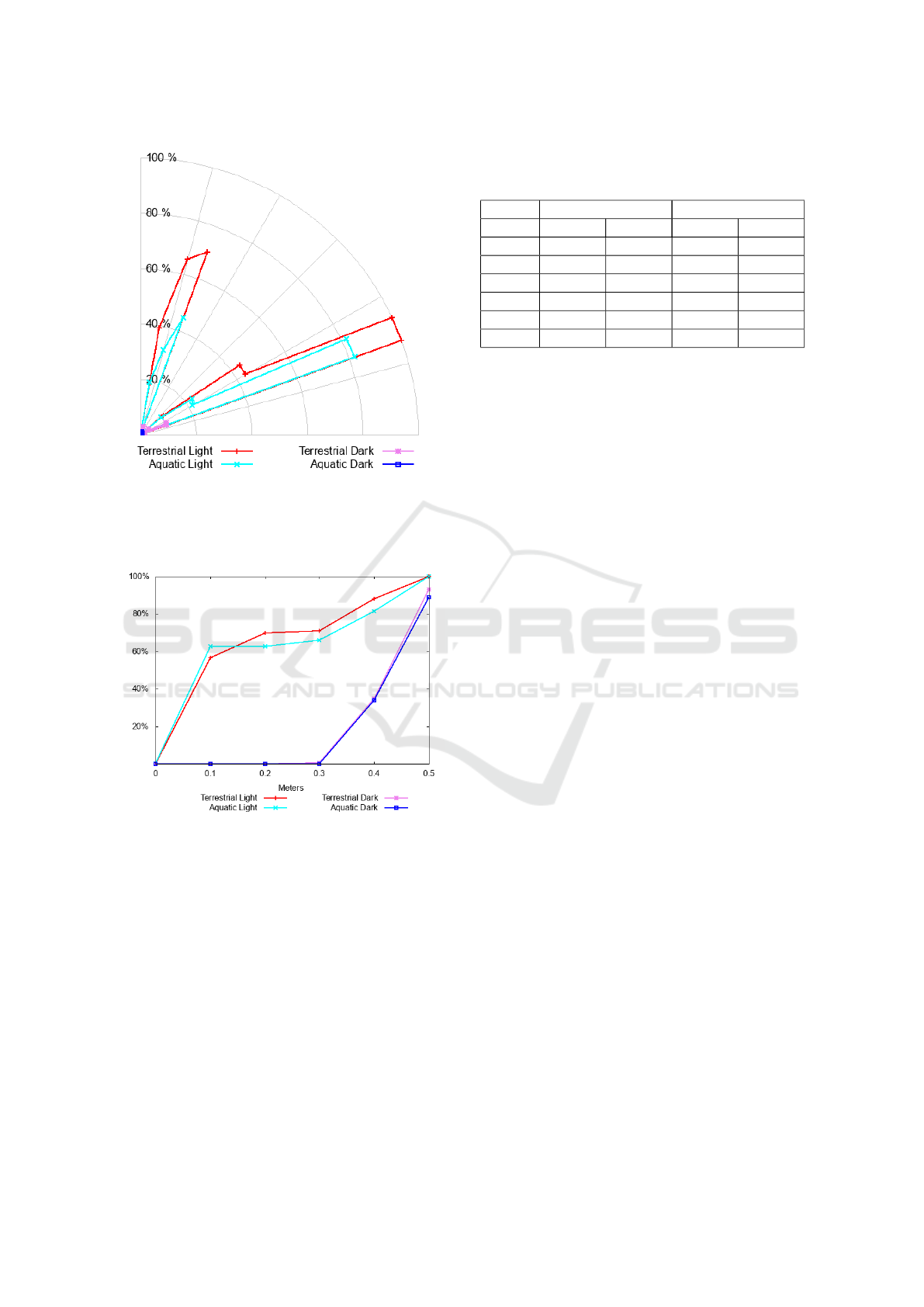
Figure 6: Radial offset packet drop-off rates. Terrestrial
light test (red), terrestrial dark test (fuchsia), aquatic light
test (cyan), and aquatic dark test (blue). Data was captured
from 0
◦
(horizontal) to 90
◦
(horizontal) offsets of 5
◦
incre-
ments.
Figure 7: Vertical offset packet drop-off rates.
tated relative to the transmitter in the light throughput
drops at the angles at which the sensor-receivers are
misaligned. Performance in the dark is excellent at all
orientations.
5.3 Planar Offset Test
Each set of three LED transmitters in the Li-Fi mo-
dem are vertically aligned along the eight walls of the
3d mount. The top and bottom LEDs are tilted 10
◦
in opposing directions. This provides a 25
◦
vertical
viewing angle with a sharp falloff in brightness at ±
45
◦
.
This experiment evaluates packet/frame drop per-
centage as a function of the vertical misalignment of
Table 4: Packet drop percentages under different environ-
ments and lighting conditions at different vertical offset dis-
tances at a range of one meter.
Terrestrial Aquatic
Offset Light Dark Light Dark
0 cm 0.01% 0.01% 0.25% 0.00%
10 cm 56.56% 0.01% 62.8% 0.00%
20 cm 69.78% 0.01% 62.66% 0.00%
30 cm 71.11% 0.50% 65.90% 0.00%
40 cm 88.23% 34.80% 81.5% 33.90%
50 cm 100.0% 93.10% 100.0% 89.00%
the transmitter and receiver. The devices were set
up 1m apart with different vertical offsets of 0cm to
50cm in increments of 10cm. Results are shown in
Fig. 7 and Table 4. Performance in the light falls off
quite quickly with vertical misalignment while perfor-
mance in the dark is good up to approximately 30cm
at 1m.
6 DISCUSSION
Li-Fi-based technology can be an effective mecha-
nism for underwater communication between a robot
and a human. For reasonably short (<5m) distances
and well aligned emitter-receiver pairs (±16
◦
) good
performance is obtained, even under illuminated con-
ditions. However, as revealed by the experimen-
tal evaluation outlined above, The current LightByte
hardware is not an ideal solution to the underwater
wireless communication problem. As currently con-
structed vertical misalignment along the axis of the
device can lead to substantive signal loss. That being
said these experiments do outline certain application
for which LightByte is well suited and other areas that
can be improved upon in future versions of the hard-
ware. For example, it would be straightforward to ex-
tend the vertical range of the device so that accurate
off-axis alignment is not required.
The performance gap between high and low am-
bient light conditions is not surprising. Performance
underwater in the light is acceptable, but performance
in lower levels of ambient illumination is very good.
As ambient illumination declines with depth this sug-
gests that transmission reliability will increase along-
side operational depth. Performance is also very good
radially save for a few problem zones. Again this is
likely to be easily addressed by increasing the density
of light detectors around the device.
Even with the current prototype implementation
transmission rates allow for the ability to transmit
joystick-like commands from a command/control de-
vice to a nearby UUV (<5m). Excess bandwidth can
ICINCO 2018 - 15th International Conference on Informatics in Control, Automation and Robotics
304

be used to transmit other relevant sensor data to/from
the robot. Considering the range/alignment limita-
tions identified in the evaluation above this would re-
quire the operator and robot to remain in the same
plane.
As far the writers are aware this is the first LIFI ca-
pable system designed for real world applications in
the underwater domain. As such it is a prototype that
demonstrates the technologies readiness to compete.
Already its has demonstrated bandwidth comparable
to that of commercially available acoustic modems.
The range of this device is a severe limitation in com-
parison to acoustic modems. This limitation is ex-
plored below.
7 FUTURE WORK
The current version of both the hardware and com-
munication protocol have a number of known limi-
tations. The Cree C503D0-WAN LEDs have a rela-
tively high luminous intensity in comparison to their
power consumption. Using LEDs that output more
lumens while sacrificing power would allow for com-
munication at a much longer distance and would also
preform much more desirably in well lit environ-
ments.
The Manchester coding scheme is very ineffi-
cient, requiring twice as much bandwidth in its en-
coded form than the raw data. IBM’s 8b/10b cod-
ing scheme(Franaszek and Widmer, 1984) is another
DC-balanced line code that has the benefit of provid-
ing additional control symbols (no decoding) that can
be used to construct a frame. 8b/10b is much more
complex that Manchester but only uses 25% overhead
bandwidth. Switching from Manchester to 8b/10b en-
coding would increase overall bandwidth by 60%.
An obviously extension to this work would be
construct an VLC device that has better out of plane
performance and with more uniform radial sensitiv-
ity. This would allow any two devices to communi-
cate with each other regardless of their relative ori-
entations, provided their bodies do not occlude the
light emitted from the device. We are in the process
of mounting the LightByte sensor on Milton with the
goal of driving the UUV underwater wirelessly from
a diver in close proximity.
ACKNOWLEDGEMENTS
This work was supported by the Natural Sciences and
Engineering Research Council (NSERC) through the
NSERC Canadian Field Robotics Network (NCFRN).
This work was also supported by the Natural Sci-
ences and Engineering Research Council (NSERC)
through the York University Vision Science to Appli-
cation (VISTA) program.
REFERENCES
Bogie, I. (1972). Conduction and magnetic signalling in
the sea a background review. Radio and Electronic
Engineer, 42(10):447–452.
Codd-Downey, R., Jenkin, M., and Allison, K. (2017). Mil-
ton: An open hardware underwater autonomous vehi-
cle. In 2017 IEEE International Conference on Infor-
mation and Automation (ICIA), pages 30–34. IEEE.
Condliffe, J. (2011). Will LIFI be the new wi-fi? Accessed
14-April-2017.
da Vinci, L. (2010). 1452-1591. Notebooks of Leonardo
da Vinci. Leonardo da Vinci’s. Note-Books Arranged
and rendered into English with Introductions. Edward
McCurdy, Kessinger Publishing, LLC.
EvoLogics (2009). Products / underwater acoustic modems
— evologics gmbh. Accessed 14-April-2017.
Fletcher, J. (1982). An arithmetic checksum for serial trans-
missions. IEEE Transactions on Communications,
30(1):247–252.
Forsberg, C. (1988). The zmodem inter application file
transfer protocol. Accessed 28-Feburary-2018.
Franaszek, P. A. and Widmer, A. X. (1984). Byte oriented
DC balanced (0, 4) 8b/10b partitioned block transmis-
sion code. US Patent 4,486,739.
Haas, H., Yin, L., Wang, Y., and Chen, C. (2016). What is
LIFI? Journal of Lightwave Technology, 34(6):1533–
1544.
IEEE (2002). IEEE standard for telecommunications and
information exchange between systems - lan/man -
specific requirements - part 15: Wireless medium ac-
cess control (mac) and physical layer (phy) specifi-
cations for wireless personal area networks (wpans).
IEEE Std 802.15.1-2002, pages 1–473.
IEEE (2013). IEEE standard for information tech-
nology - telecommunications and information ex-
change between systemslocal and metropolitan area
networks– specific requirements–part 11: Wireless
lan medium access control (mac) and physical layer
(phy) specifications–amendment 4: Enhancements for
very high throughput for operation in bands below
6 ghz. IEEE Std 802.11ac-2013 (Amendment to
IEEE Std 802.11-2012, as amended by IEEE Std
802.11ae-2012, IEEE Std 802.11aa-2012, and IEEE
Std 802.11ad-2012), pages 1–425.
ISO (2008). ISO/IEC 18000-1:2008 information technol-
ogy – radio frequency identification for item manage-
ment – part 1: Reference architecture and definition of
parameters to be standardized. Accessed 12-March-
2018.
ISO (2013). ISO/IEC 18092:2013 information technology
– telecommunications and information exchange be-
LightByte: Communicating Wirelessly with an Underwater Robot using Light
305

tween systems – near field communication – interface
and protocol (nfcip-1). Accessed 12-March-2018.
Kaushal, H. and Kaddoum, G. (2016). Underwater optical
wireless communication. IEEE Access, 4:1518–1547.
Medhekar, P., Mungekar, S., Marathe, V., and Mehar-
wade, V. (2016). Visible light underwater communica-
tion using different light sources. International Jour-
nal of Modern Trends in Engineering and Research,
3(4):635–638.
Quazi, A. and Konrad, W. (1982). Underwater acoustic
communications. IEEE Communications Magazine,
20(2):24–30.
Rajagopal, S., Roberts, R. D., and Lim, S. K. (2012).
IEEE 802.15.7 visible light communication: modula-
tion schemes and dimming support. IEEE Communi-
cations Magazine, 50(3):72–82.
Tanenbaum, A. S. and Wetherall, D. J. (2011). Computer
Networks. Pearson.
Wang, C., Yu, H.-Y., and Zhu, Y.-J. (2016). A long dis-
tance underwater visible light communication system
with single photon avalanche diode. IEEE Photonics
Journal, 8(5):1–11.
ICINCO 2018 - 15th International Conference on Informatics in Control, Automation and Robotics
306
