
Pitching and Catching of an Object between a Pair of Air Jet
Nobukado Abe
1
, Satoshi Iwaki
1
, Kazuki Yoshinaga
1
, Naoki Tsuchihashi
1
,
Tetsushi Ikeda
1
, Toshiharu Kosaku
1
and Takeshi Takaki
2
1
Systems Engineering Robotics Laboratory, Graduate School of Information Science, Hiroshima City University, 3-4-1,
Ozukahigashi, Asaminami-ku, Hiroshima, Japan
2
Graduate School of Engineering, Hiroshima University, 3-3-2, Kagamiyama, Higashihiroshima, Hiroshima, Japan
Keywords: Air Jet, Pitching, Catching, Manipulation, 3D.
Abstract: We have been studying an air jet manipulation technology to non-contactly carry an object over a long
distance using multiple 3D air jet manipulation modules consisting of a single air jet nozzle and a pan-tilt
actuator. Here we challenge long distant transportation through object pitching-and-catching between a pair
of air jet. In this report, we propose a control algorithm to determine each air jet angle and its flow rate, for
both pitching side and catching side. First we try to observe human behaviour in a real catch-ball as a hint to
create the algorithm. Next, as a preliminary experiment, a pitching experiment and a catching experiment are
independently performed to obtain an air jet output function and a control law for each. After that, we propose
an integrated transporting algorithm of pitching and catching, and confirm its validity by demonstration
experiment.
1 INTRODUCTION
Non-contact object manipulation technology using
air jets has excellent features such as cleanness and
no need for a transmission mechanism. It has been
extensively studied for some years mainly aiming at
an application to a conveying system for relatively
smaller and lighter objects. On a flat plane, the 3-DOF
(two translational DOF + one rotational DOF) control
method for a single object by changing the flow rate
and angle of three and four air jet nozzles has been
proposed (Yamamoto et al.,2009), (Iwaki et al., 2011),
(Matsushita et al., 2014), (Matsushita et al., 2016),
(Tsuchihashi et al.,2016) . Furthermore, an extension
to position control of multiple objects has been
reported (Matsushita et al., 2016). Moreover, in a
three-dimensional space, the three translational DOF
control method using a single air jet nozzle mounted
on a pan-tilt actuator has been proposed (Becker et
al., 2009). In this research, it is possible to freely
control the translational 3-DOF within the range
where the object can be held by the Coandă effect.
However, since the range in which an object can be
held against gravity is at most about 40 degrees, the
driving range is inherently narrow. In order to solve
this problem, we reported a relaying transport
technique by multiple nozzle (Iwaki et al., 2017). In
this research, a long-distance conveyance is realized
by arranging multiple nozzles along a conveying line
and directly relaying them one by one. However, in
order to realize more reasonable conveyance in a
three-dimensional space, it is essential to extend the
distance between the nozzles. Therefore, we propose
an object conveying method between nozzles that are
away from each other by exploiting hints of real
catch-ball by human. Since it is very difficult to
theoretically calculate the force exerted by an air jet
on an object with fluid dynamics, we experimentally
address to this issue using actual equipment. With this
proposed method, we can expect to drastically reduce
the number of nozzles required for long distance
transport.
2 PROPOSED METHOD
2.1 Formulation of Problem
In a vertical plane YZ as shown in Fig. 1, let’s
consider a pair of air jet nozzle located at the same
height with
distance. We challenge to pitch a ball
from the pitching nozzle and then to catch it by the
catching nozzle. Here our problem is to determine the
Abe, N., Iwaki, S., Yoshinaga, K., Tsuchihashi, N., Ikeda, T., Kosaku, T. and Takaki, T.
Pitching and Catching of an Object between a Pair of Air Jet.
DOI: 10.5220/0006857603130317
In Proceedings of the 15th International Conference on Informatics in Control, Automation and Robotics (ICINCO 2018) - Volume 2, pages 313-317
ISBN: 978-989-758-321-6
Copyright © 2018 by SCITEPRESS – Science and Technology Publications, Lda. All rights reserved
313
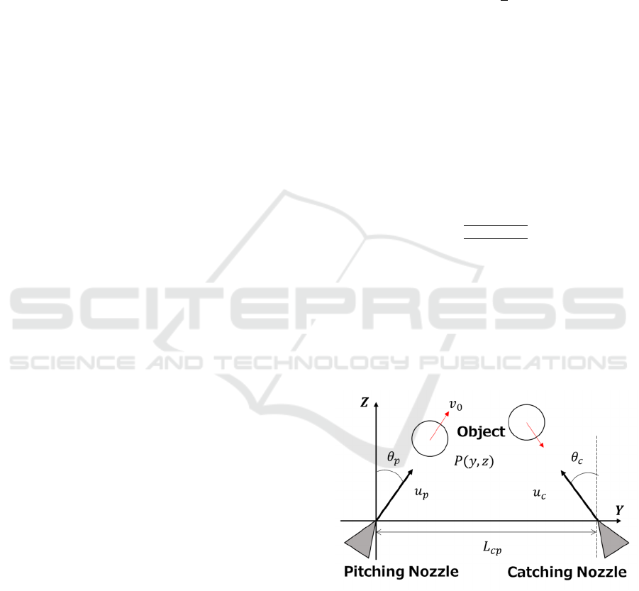
angles
,
[deg] and the air jet flow rate
,
[V]
(input for a proportional solenoid valve) of the both
air jet nozzles. The coordinate value of the ball’s
centre is denoted as
,
.
2.2 Observation of Human Behaviour
in a Real Catch-Ball
In order to solve the above problem, first let us
observe human behaviour in a real catch-ball. Then
the following typical features of human behaviour
will be recognized.
Pitcher: The pitcher gauges the distance to the
catcher and throws a ball to reach the catcher’s chest
so that the catcher can easily grab the ball by hand. In
order to send it in a short time, it is necessary to bring
the trajectory close to horizontal. In other words, it is
necessary to increase the initial velocity of the ball.
Catcher: The catcher constantly observes and
predicts the ball trajectory, thereby determining the
catching position of the hand. Furthermore, by pulling
the hand along the ball trajectory according to the
speed of the ball, the catcher can stably grab the ball
catching without bounce when contacting the glove.
2.3 Requirements and Strategies
From the above consideration, the following
requirements are set in our proposed method.
Pitching nozzle: Determine the initial speed and
pitching angle so that it reaches the tip of the catching
nozzle.
Catching nozzle: The nozzle angle is determined
by always observing the object position. Capture the
object on the air jet, give an air jet flow that cancels
its velocity near the nozzle and stop it at the given
position. However, due to the nature of the Coandă
effect, the nozzle angle is operated within the range
of the angle
[deg] at which the object can be
sufficiently stably held in the air jet.
Based on the above requirements, the following
control strategy will be formulated.
(A) Determine the pitching angle based on
.
Fly the ball toward the tip of the catching nozzle.
(B) The object positon is constantly measured by an
external camera and the trajectory is predicted.
(C) The catching nozzle constantly aims at the
center of gravity of the object.
(D) The catching nozzle controls the air jet flow rate
to keep constant the distance to the object.
2.4 Proposed Control Laws
From the above (A)-(D), each manipulated variable is
formulated as follows.
,
(1)
(2)
(3)
(4)
Here
, is a constant angle which can be
freely determined, where
is a maximum nozzle
angle in which the object can be stably held with the
Coandă effect in a space.
,
is a pulse
function giving the initial velocity
[m/s] to the
object, where
is the initial velocity required for
pitching the object at the pitching angle
, and is
obtained from the parabolic motion equation as
follows;
(5)
Also, the object position
,
is measured in real
time by a camera, or acquired based on the state
observation method such as the Kalman filter. Eq. (4)
is a speed type PID compensator for controlling so
that the distance between the object nozzles
[mm]
follows the target distance
[mm].
Figure 1: Schematic diagram of proposed system.
3 PRELIMINARY EXPERIMENT
Before an experiment based on the proposed control
law, some preliminary experiments were conducted
as described below. An overview of the experimental
ICINCO 2018 - 15th International Conference on Informatics in Control, Automation and Robotics
314
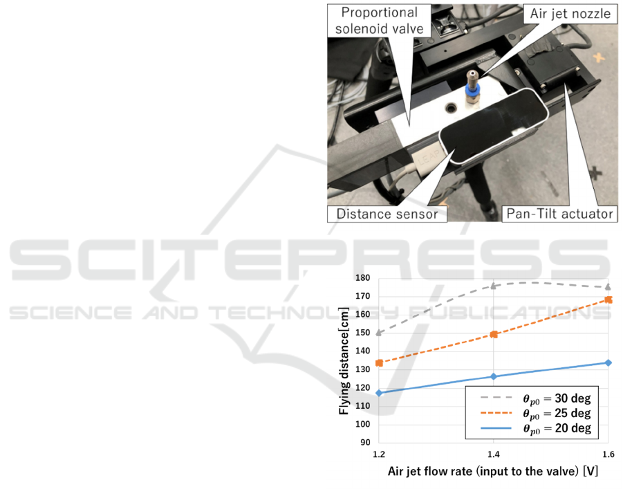
system is shown in Fig. 2. The air pressure supplied
to the air jet nozzle is 0.40 MPa.
3.1 Determination of the Pulse
Function by Pitching Experiment
Therefore, here we have performed a preliminary test
for experimentally determining the pulse function
,
of Eq. (2). Using a ball with a mass of
10.2 g and a diameter of 100 mm, the floatable
minimum output
= 0.6 V was determined. And
from the steady state in open loop control, various
pulses were exerted to the ball to measure the flying
distance. The pulse width is fixed to 0.2 seconds, the
pulse heights are of 3 types of 2
, 2.3
,
2.6
, and
are three types of 20, 25, 30
degrees. The measurement results are shown in Fig.
3. From these graphs, since the behaviour of the
object due to pulse output became clear, a pulse
function that achieves an arbitrary flying distance was
determined in the form of an inverse function.
3.2 Tuning of PID Controller for
Catching
In order to adjust the PID parameter, an experiment
was conducted in which the object was naturally
dropped vertically from a height of about 1 m to catch
an object. In order to confirm the effect of feedback
control, experiments with no control (
constant)
were compared with experiments with speed type PID
control (Fig. 4). In Fig. 4, the horizontal axis
represents the time, the upper half of the vertical axis
shows the displacement of distance between the
catching nozzle and the object in during open loop
control and PID control, and the lower half shows the
air jet flow rate (input for the proportional solenoid
valve) in during PID control. Here we define a
successful catching if the object stays within 50 mm
error for a target distance 180 mm. From these
figures, excellent vibration suppression and target
value tracking performance by feedback control can
be confirmed. In the case where the deviation greatly
changes as in this experiment, by using speed type
PID control, the responsiveness of
can be
increased, and as a result, the speed of the object
rapidly decreases and
can promptly follow
.
Note
that there are large vibration in the air jet flow rate
graph due to poor resolution of the distance sensor,
which should be improved in the future.
3.3 Measurament of
By tilting the air jet angle, the object holding force by
the Coandă effect was experimentally investigated.
was varied in the range of 0 to 50 degrees from the
vertical while the object was held by the air jet by the
control system of Section 3.2. As a result, it was
found that in this experimental environment, stable
object holding is possible up to about 40 degrees at
maximum.
Figure 2: An experimental system overview.
Figure 3: Flying distance of the object from the pitching
nozzle.
4 PITCHING-AND-CATCHING
EXPERIMENT
We conducted an experiment in which throwing and
catching are performed automatically under the same
experimental conditions as in the preliminary
experiment in Section 3. At this time, the pitching
nozzle angle was 25 degrees, the pulse function
Pitching and Catching of an Object between a Pair of Air Jet
315
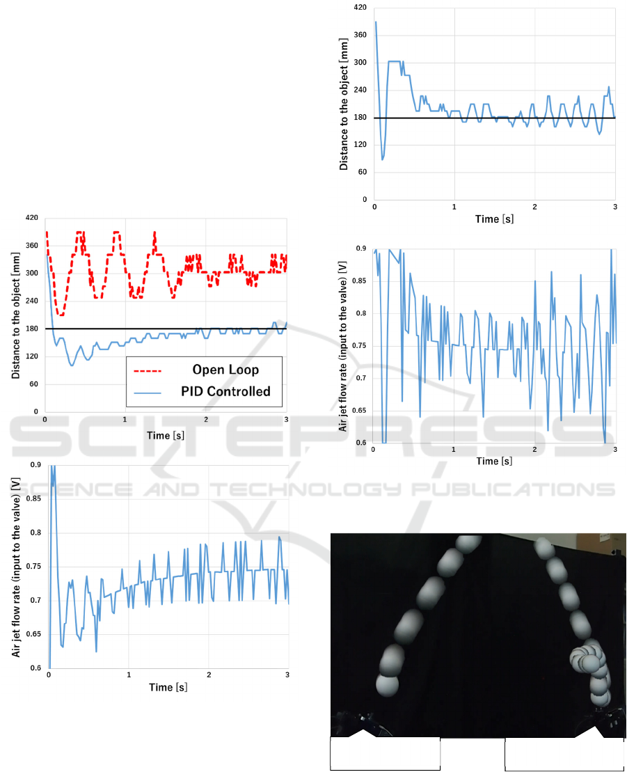
,
was 1.2 V output, and the pulse width was
0.2 s. From the average value of the flight distance
under these conditions, the distance between both
nozzles was set to 1.3 m. Trajectory of the object and
experimental results at the catching nozzle are shown
in Fig. 5, 6. Based on the same reason in Section 3.2,
very large vibration are observed in the air jet flow
rate graph. Nevertheless, we can confirm that the
distance to the nozzle was smoothly stabilized and, as
a result of that, the ball was successfully caught by
the catching nozzle. From the above, we can confirm
the validity of our proposed method.
Figure 4: Distance between the object and the catching
nozzle, and the air jet flow rate (vertical case).
Figure 5: Distance between the object and the catching
nozzle, and the air jet flow rate with the proposed method.
Figure 6: Trajectory of the object.
Pitching nozzle
Catching nozzle
ICINCO 2018 - 15th International Conference on Informatics in Control, Automation and Robotics
316

5 CONCLUSIONS
In this paper, we challenged a long distant and non-
contact transportation through object pitching-and-
catching between a pair of air jet. We proposed a
control algorithm to determine each air jet angle and
its flow rate, for both pitching side and catching side.
Several experiments results have shown the validity
of the proposed method, and it was possible to extend
the conveying distance. In the future, we will improve
the system, and generalize the object and the
experiments.
REFERENCES
Yamamoto, Takaki, Ishii, 2009. Non-contact Manipulation
on Flat Plate Using Air-jet Streams. The Robotics
Society of Japan.
Iwaki, Morimasa, Noritsugu Kobayashi, 2011. Contactless
Manipulation of an Object on a Plane Surface using
Multiple Air Jets, Proc. of ICRA. pp.3257-3262. K.
Elissa.
Matsushita, Sugiyama, Tsuji, Iwaki, et al., 2014.
Contactless Object Manipulation Using Multiple Air
Jets on Planar Surface (Experimental Case Studies for
Small Control Range with Continuous Air Jets).
Transactions of the JSME, Vol.80, No.817.
Matsushita, Tsuchihashi, Iwaki, Takaki, Kosaku, 2016.
Contactless Object Manipulation Using Multiple Air
Jets on Planar Surface (Experimental Case Studies of
Control Method for the Multiple Objects Using Four
Air Jets Nozzles). Transactions of the JSME,
DOI:10.1299/transjsme.15-00459.
Tsuchihashi, Yoshinaga, Iwaki, et al., 2016. Non-contact
Manipulation of a Single Solid Object on a Plane
Surface Using Multiple Air Jets (Experiment for the
Application of Fuzzy Control). Advanced Mechatronic
Systems (ICAMechS), International Conference on.
Becker, A., Robert, S., Timothy, B., 2009. Automated
Manipulation of Spherical Objects in Three
Dimensions Using a Gimbaled Air Jet. Proc. of IROS,
pp.781-786.
Iwaki, Tsuchihashi, Yoshinaga et al., 2017. 3D Object
Manipulation System Using Multiple Air Jets.
Innovation JAPAN, M-69.
Pitching and Catching of an Object between a Pair of Air Jet
317
