
3D Pose Estimation of Bin Picking Object using Deep Learning and
3D Matching
Junesuk Lee
1
, Sangseung Kang
2
and Soon-Yong Park
1
1
School of Computer Science and Engineering, Kyungpook National University, Daegu, South Korea
2
Intelligent Robotics Research Division, Electronics and Telecommunications Research Institute, Daejeon, South Korea
Keywords: Bin Picking, Pose Estimation, Object Detection, Deep Learning, 3D Matching.
Abstract: In this paper, we propose a method to estimate 3D pose information of an object in a randomly piled-up
environment by using image data obtained from an RGB-D camera. The proposed method consists of two
modules: object detection by deep learning, and pose estimation by Iterative Closest Point (ICP) algorithm.
In the first module, we propose an image encoding method to generate three channel images by integrating
depth and infrared images captured by the camera. We use these encoded images as both the input data and
training data set in a deep learning-based object detection step. Also, we propose a depth-based filtering
method to improve the precision of object detection and to reduce the number of false positives by pre-
processing input data. ICP-based 3D pose estimation is done in the second module, where we applied a
plane-fitting method to increase the accuracy of the estimated pose.
1 INTRODUCTION
With the rapid development of modern visual
recognition technology, many advanced systems
have been introduced to automate the works of
assembly lines in large industries. Such automation
is achieved by implementing high-tech robots,
mainly on the seek of increasing productivity and
efficiency. Consequently, the topic bin-picking has
started to attract the attention of many researchers.
In computer vision society, this topic is defined as
“the method of estimating the pose of randomly
piled-up objects, and sending pose data to robots to
act accordingly.”
From the past to the present, a large number of
bin-picking research works have been actively
conducted. Kuo et al. proposed an automatic system
for object detection and pose estimation using a
single depth map (Kuo et al., 2014). Object detection
is based on matching key-points (using RANSAC
algorithm (Schnable et al., 2007)) extracted from the
depth image, where pose estimation is achieved by
applying ICP algorithm (Besl and McKay, 1992).
Wu et al. introduced a method to estimate object
pose by using a CAD model, where they applied a
voxel grid filter (Skotheim et al, 2012) to reduce the
total computation time (Wu et al., 2015). Wada et al.
proposed a Convolution Neural Network-based
(CNN) object recognition and splitting method for
objects that are stacked in narrow spaces (Wada et
al., 2016). Radhakrishnamurthy et al. researched
about an automated stereo bin-picking system and
proposed the ATOT (Acclimatized Top Object
Threshold) algorithm to identify the top-most object
in a pile of occluded objects (Radhakrishnamurthy et
al., 2017). Instead of using a threshold value for
binarization (Otsu, 1979) through trial-and-error,
they advanced their algorithm to find the correct
threshold value automatically. He et al. proposed a
pipeline to reduce the number of false positives in
object detection (He et al, 2017). They used template
matching and clustering algorithms to detect objects,
and their point cloud processing algorithm to
estimate the object pose.
Even though these existing methods are capable
of obtaining promising results, most of them have
two common drawbacks: Unstable corresponding
point matchings in object detection, and insufficient
3D point data acquisition in ICP-based pose
estimation. In this paper, we address these
drawbacks and introduce an effective bin-picking
system by utilizing computer vision, and deep-
learning techniques. We divide our approach into
two modules, an object detection module, and a pose
estimation module. In the first module, we propose
318
Lee, J., Kang, S. and Park, S-Y.
3D Pose Estimation of Bin Picking Object using Deep Learning and 3D Matching.
DOI: 10.5220/0006858203180324
In Proceedings of the 15th International Conference on Informatics in Control, Automation and Robotics (ICINCO 2018) - Volume 2, pages 318-324
ISBN: 978-989-758-321-6
Copyright © 2018 by SCITEPRESS – Science and Technology Publications, Lda. All rights reserved
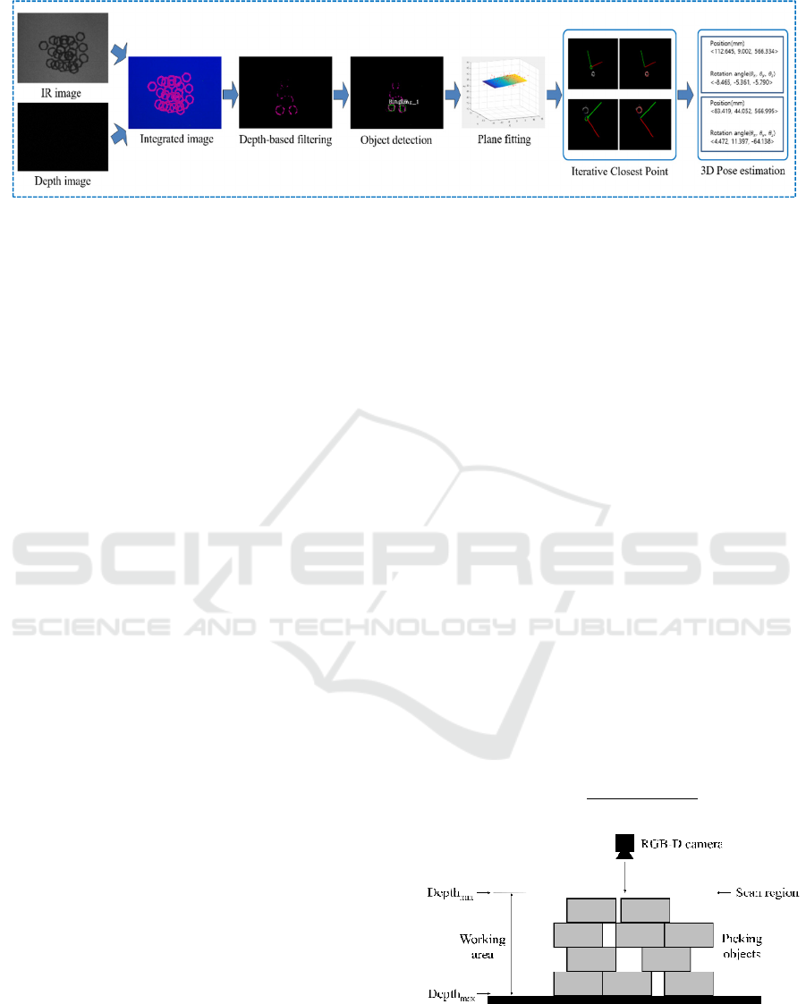
Figure 1: Proposed system flowchart.
an encoding method to integrate IR and depth
images of the camera to generate a new-3-channel
image and a depth-based filtering method to improve
deep learning-based object detection precision. In
the second module, we use the ICP algorithm to
estimate the pose of the first module’s detected
objects. To solve insufficient 3D point data problem,
we apply plane-fitting (Radu and Cousins, 2011) to
move the plane equation of the surface in the direct-
ion of its normal vector. This approach increased the
total number of matching points of the object.
Fig. 1 shows the flow chart proposed in this
paper to estimate the pose of an object. First, an
infrared image and a depth image are obtained from
an RGB-D camera. Then, the two images of the
previous stage are integrated into one image by the
proposed method. This integrated image is used as
training-data to train YOLO(You only look once)
v2(Redmon and Farhadi, 2017). Then, we apply the
depth-based filtering proposed in this paper to this
integrated image. The reason for applying this
filtering is to solve the problem that it is difficult for
the detector to detect an object if the objects overlap
each other. Then we detect the object with a detector
trained with YOLO v2. Next, the point cloud of the
detected object is obtained using the perspective
back-projection transformation. Then, as in section
3.1, we use PCL(Point Cloud Library)'s plane-fitting
algorithm to acquire an additional point cloud of
objects. Finally, we use PCL's ICP algorithm to
estimate the pose of the object using the acquired
point clouds and the CAD model of the object. In
this paper, we study two kinds of objects. We
randomly piled objects to make an experimental
environment. However, we do not mix two kinds of
objects in one experimental environment.
The structure of our paper is as follows. The first
module: image encoding and object detection are
introduced in section 2, where ICP-based pose
estimation is stated in section 3. We validated the
accuracy of two modules through experimental
results and summarized them in section 4. Lastly,
conclusions are summarized in the final section of
this paper.
2 IMAGE ENCODING AND
OBJECT DETECTION
2.1 Generating 3-channel Encoded
Image
A time-of-flight (ToF) camera is a range imaging
capable camera that resolves distance to points in 2D
images. Kinect v2 is a ToF-type camera capable of
producing both depth and infrared images
(Butkiewicz, 2014). Even though ToF-type cameras
have an illumination variant characteristic, they are
less likely to be influenced by lighting conditions in
indoor environments. Based on this assumption, in
this paper, we created a three-channel image using
depth and IR images acquired from Kinect v2 using
the following method.
First, we normalize the depth value of the depth
image using Eq. (1) and then assign this value to the
first channel(channel
1).
Channel
1
=
Depth
input
-Depth
min
Depth
max
-Depth
min
(1)
Figure 2: A graphical representation of how bins are piled-
up. The RGB-D camera is mounted on top of the bin.
Fig. 2 depicts a general situation where objects are
piled-up on a flat surface. Depth
input represents the
3D Pose Estimation of Bin Picking Object using Deep Learning and 3D Matching
319
depth data obtained from the RGB-D camera, where
Depth
min and Depthmax represent the distances to
starting and end positions of the user-defined
working area from the camera. The starting point is
not necessarily the starting point of the first piled
bin. Second, we assigned original data of the IR
image to the second channel(channel
2
). To
summarize the first and second channels, the first
channel is assigned a normalized depth value, and
the second channel is assigned a normalized value of
the pixel size of the IR image.
Finally, we used the predefined thresholds to
remove the background of the IR image and assign
the normalized value to the third channel(channel
3)
using Eq. (2). This method emphasizes the shape of
an object by making the difference between the
object and the background large. The reason for
doing this is to make the features of the object
stronger when training the deep learning model. In
Eq. (2), the constant value is an experimentally
obtained value. Fig. 3 shows an example of the
process of creating a 3-channel image using the
proposed method. In Fig. 3, the right image is the IR
image and the depth image, and the left image is the
resulting image.
Channel
3
=128+pixel_value×6 (2)
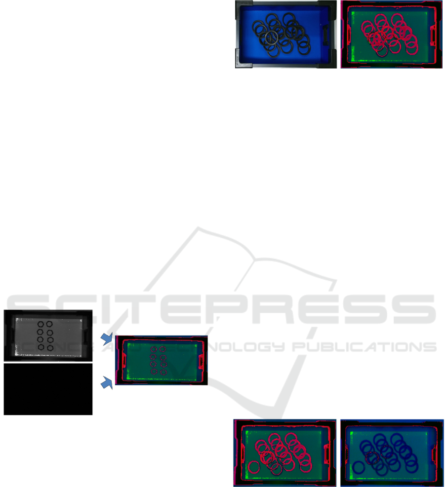
Figure 3: Creating a 3-channel image using IR image and
depth image.
2.2 Depth-based Filtering
Detecting target objects when they are overlapped
with each other is not an easy task. Overlapping
results in changing the characteristics of individual
objects. This is a very common issue in objects with
holes in their center. For example, as in the case of
Fig. 4, the object detector falsely recognizes two or
more overlapping objects as a single object.
We propose a recursive depth-based filtering
method to solve this problem. This is a method of
acquiring data between distance threshold from the
camera position in the work area. This method
applies to the only channel
3 in the encoded image.
(a) (b)
Figure 4: Examples of target objects piled up in a
rectangle box (a) color image (b) proposed encoding
image.
Taking Fig. 2 as an example, our proposed filtering
method is to remove data located farther away than
the red line based on the camera position. This red
line indicates the vertical search area from the
camera position to the distance threshold. The data
removal method is to set the pixel having a value
greater than the distance threshold to zero. In the
next step, this filtered image is used to detect the
object using the object detector. When this task is
completed, the distance threshold is incremented by
1 mm to repeat the task. We set the initial distance
threshold to Depth
min and the maximum value to
Depthmax.
This process is performed recursively until all
the objects are detected. Fig. 5 (a) shows the image
before depth-based filtering is applied. Fig. 5(b)
shows an example that depth-based filtering is
applied to the image that captures the situation
where objects overlap each other. The red circle in
Fig. 5(b) represents the target object detected in the
search region. Pixels which depth is larger than the
threshold value are regarded as background and
represented with blue. This representation allows to
easily identify objects even they overlap with each
other.
(a) (b)
Figure 5: Depth filtering (a) before depth-based filtering
(b) after depth-based filtering.
2.3 Target Object Detection using Deep
Neural Network
In this paper, we trained the object detector using the
YOLO v2 (Redmon and Farhadi, 2017) library. The
YOLO v2 library uses the Dartnet-19 model. This
model has 19 convolutional layers and 5 maxpooling
ICINCO 2018 - 15th International Conference on Informatics in Control, Automation and Robotics
320
layers. We have collected training data as shown in
Fig. 6(a) to train this deep learning model. Fig. 6(b)
shows the labeling information of the training data
(Fig. 6(a)). In this paper, the input image of the
object detector is the depth-based filtered image and
the output is the area of the detected object. Fig. 7
shows an example of the results of detecting objects
using an object detector.
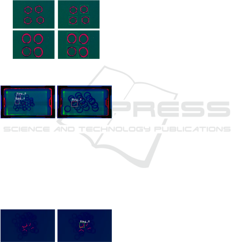
(a) (b)
Figure 6: Example of training data, (a) Training data (b)
Labelling image of training data.
(a) (b)
Figure 7: Object detection examples using YOLO v2, (a)
detected object regions of hexagonal rings (b) detected
object regions of circular rings.
Occasionally, objects are tilted in the working
environment. If depth-based filtering is applied in
this case, the result as shown in Fig. 8(a) is output.
However, the object detector we trained do not
detect the object. Because we did not train an object
like Fig. 8(a). If an object is not detected, depth-
based filtering increases the depth threshold. When
it looks like Fig. 8(b), the detector detects the tilted
object.
(a) (b)
Figure 8: A case with an inclined object, (a) Object
detector does not detect the object (b) After increasing the
depth threshold, the object detector detects the object.
3 3D POSE ESTIMATION OF
TARGET OBJECTS
3.1 Plane Fitting of the Object Top
Once the object regions are detected, we use the ICP
algorithm in each object region to estimate the pose
of the objects. We acquire a 3D point cloud using
the perspective back-projection transformation
formula for the region detected in the previous step.
This point cloud is matched with the 3D CAD model
of the object to find the 3D rotation and translation.
The model of the object is also represented by 3D
points. In general, ICP algorithm works better if the
number of 3D points of the object is large. There
arises a problem of insufficiently acquiring the
perspective back-projection-converted 3D points
because the pixels exist only in the upper part of the
object in the 2D image. Therefore, in this paper, we
employ a plane fitting method to acquire more 3D
points for the target object.
Suppose we obtain the 3D point clouds for a
detected target object which is reconstructed from
the object region in the depth image. An example is
shown in Fig. 9(a). This point cloud is represented as
P
x
1
,y
1
,z
1
,…,
x
κ
,y
k
,z
κ
. The plane equation
(Eq. (3)) is fitted to this point cloud as shown in Fig.
9(b). The direction of the normal vector
as in Eq.
(4) is always opposite to the coordinate origin
because c and z values are positive in this equation.
To obtain enough 3D points from the depth, the
fitted plane is shifted along the normal direction by a
short length (δ) as shown in Fig. 9(c). Then, more
points which satisfy Eq. (5) are added to the point
clouds . In Eq. (5), is uniform distribution.
0 0, 0 (3)
,, (4)
δ
0with~1,K
(5)
In summary, once, the plane equation as shown
in Fig. 9(b) is obtained through the plane fitting for
the point cloud of the object as shown in Fig. 9(a).
Then, the plane equation as shown in Fig. 9(b) is
moved in parallel to the normal vector direction by a
certain size(δ). We acquire closer points from the
plane relative to the origin and use it as a data set for
ICP algorithm. The origin indicates the position of
the camera. By applying this method, we can acquire
more 3D points for the object than before.
3D Pose Estimation of Bin Picking Object using Deep Learning and 3D Matching
321
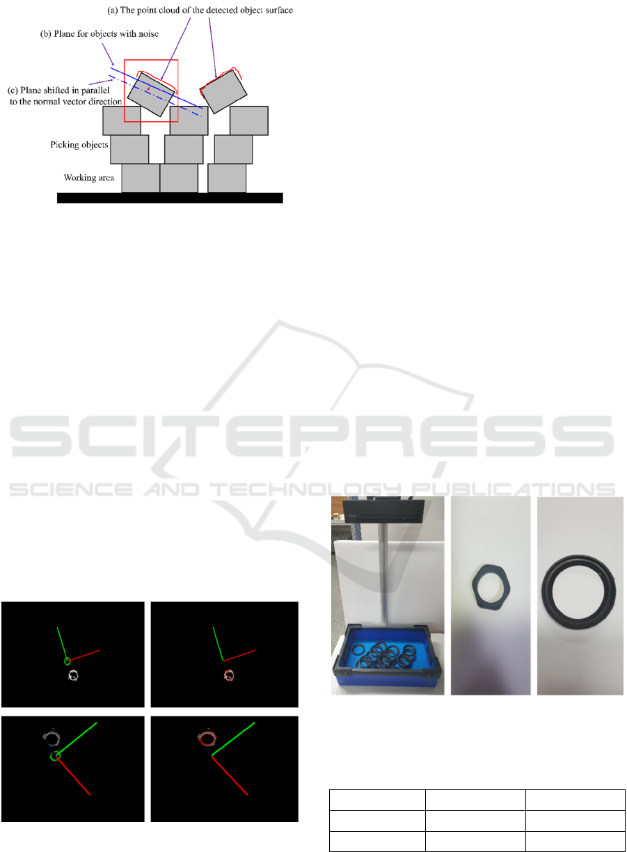
Figure 9: Plane fitting and Shifting along the plane normal
direction.
3.2 3D Pose of Target Object
The pose of a target object means the 3D
transformation of the object from the origin of the
depth sensor. The 3D pose of target object must be
known to perform the picking task of a robot system.
The 3D pose of a target object is estimated by the
following method.
First, we create 3D models of the two target
objects. The 3D target models are also point clouds
data which has the same scale with the target
objects. In Fig. 10(a), one of the target models is
placed at the coordinate origin in green color. The
coordinate origin is defined as the coordinate of the
RGB-D camera used in experiments.
Next, the point cloud of the object obtained
through the plane shift method is matched with the
point cloud of the target model using the ICP
algorithm. The pose of the object is estimated
through the translation and rotation matrices of the
3D transformation derived by the ICP algorithm.
(a) (b)
Figure 10: Two examples of ICP matching (a) Before 3D
matching (b) After 3D matching.
In Fig. 10(b), the target model, red-colored
points, is matched with the target object, white-
colored points, after applying the ICP algorithm.
4 EXPERIMENT RESULTS
4.1 Experiment Environment
To verify the performance of the proposed system,
an experimental set is constructed as shown in Fig.
11(a). As target object two types of ring are used,
hexagonal ring(Fig. 11(b)) and circular ring(Fig.
11(c)). The hexagonal ring has 5mm height and
45mm diameter, and there is a circular hole of
diameter 30mm. The circular ring has 10mm height
and 70mm diameter, and there is a circular hole of
diameter 55mm.
The number of training data is shown in Table 1
and it is trained by YOLO v2 library. The
experimental method is as follows. First, we detect
the target objects in depth images by the trained
detector. Then, a target object is randomly selected
from among the detected objects. After obtaining the
3D pose information of the object, it is manually
removed to simulate robotic bin picking. The
simulated picking task is repeated until all target
objects are removed and no object is detected. In this
experiment, we excluded the case where the object
was largely inclined.
(a) (b) (c)
Figure 11: (a) Experimental setup (b) Hexagonal ring (c)
Circular ring.
Table 1: Number of Training Data.
Training image Test image
Hexagonal ring 454 323
Circular ring 283 207
ICINCO 2018 - 15th International Conference on Informatics in Control, Automation and Robotics
322
4.2 Experiment Results
Table 2 and Table 3 show the results of pose
estimation of two types of target objects. The target
objects are randomly placed in a rectangle box. The
number of object in a pile is 30 for the hexagonal
object, 20 for the circular object. In each object type,
experimental tests are done in five times. The single
test consists of picking all detected objects out of the
box.
TP(True Positive) in Tables 2 and Table 3 are
cases that the following two conditions are satisfied.
The first condition is that when the target model,
transformed to the target object by ICP algorithm, is
projected onto the image of the target. In case of
correct estimation, the projected image is exactly
matched with the image of the target object. The
second condition is when a target object is detected
in the object piled, it must be one of the topmost
objects.
FP(False Positive) means the following two
cases. The first case refers to a situation in which an
object other than the topmost object is detected in
the object piled. The second case refers to a case that
a detected object region overlaps two objects.
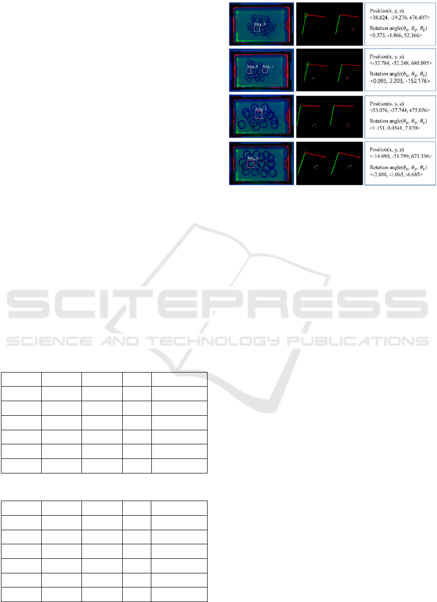
Fig. 12 shows some of the experiment results.
Fig. 12(a) shows object regions decided by the deep
neural network. Fig. 12(b) shows the pose between
the target model and target object before and after
ICP algorithm. The rotation and translation of the
object pose are shown in Fig. 12(c).
Table 2: Experimential results on hexagon al rings.
TOTAL TP FP Precision(%)
TEST 1 30 25 5 83.3
TEST 2 30 26 4 86.6
TEST 3 30 26 4 86.6
TEST 4 30 26 4 86.6
TEST 5 30 25 5 83.3
150 128 22 85.3
Table 3: Experimental results on circular rings.
TOTAL TP FP Precision(%)
TEST 1 20 17 3 85.0
TEST 2 20 18 2 90.0
TEST 3 20 17 3 85.0
TEST 4 20 17 3 85.0
TEST 5 20 17 3 85.0
100 86 14 86.0
(a) (b) (c)
Figure 12: (a) Object detection (b) 3D matching (c) Pose
estimation.
5 CONCLUSION
In this paper, we propose a method for estimating
the 3D pose of target objects in an environment
where objects are randomly piled up. We proposed
an image encoding method of integrating a depth
image and an infrared image which are robust to
illumination changes. We trained and detected
encoded images by YOLO v2. However, if objects
with holes in the center are randomly piled up, there
is a problem that it is difficult to detect because
objects appear to cover each other and the middle
part is filled with something else. We have solved
this problem with the proposed depth-based filtering
method. Furthermore, we proposed a method of
acquiring more 3D points by both plane fitting
algorithm and plane shift to obtain better results of
ICP algorithm. Finally, we estimated the pose of the
objects by ICP algorithm.
ACKNOWLEDGEMENTS
This research was supported by MoTIE and
Industrial Core Technology Development Program
of Korea Evaluation Institute of Industrial
Technology (KEIT) (10063413)
3D Pose Estimation of Bin Picking Object using Deep Learning and 3D Matching
323

REFERENCES
Kuo, H. Y., Su, H. R., Lai, S. H., 2014. 3D Object
Detection and Pose Estimation from Depth Image for
Robotic Bin Picking, IEEE International Conference
on Automation Science and Engineering (CASE), pp.
1264-1269.
Schnable, R., Wahl, R. and Klein, R., 2007. Efficient
RANSAC for point-cloud shape detection, Computer
Graphics Forum (CGF), Vol. 26, no. 2, pp. 214-226.
Besl, P. J., and McKay, N. D., 1992. Method for
registration of 3-D shapes, Sensor Fusion : Control
Paradigms and Data Structures, vol. 1611, pp. 586-
607.
Wu, C. H., Jiang, S. Y., and Song, K. T., 2015. CAD-
Based Pose Estimation for Random Bin-Picking of
Multiple Objects Using a RGB-D Camera, IEEE 15th
International Confrence on Control, Automation and
Systems (ICCAS), pp. 1645-1649.
Skotheim, Ø, Lind, M., Ystaard, P., and Fjerdingen, S. A.,
2012. A Flexible 3D object localization system for
industrial part handling, IEEE/RSJ International
Conference on Intelligent Robots and Systems (IROS),
pp. 3326-3333.
Wada, K., Murooka, M., Okada, K., and Inaba, M., 2016.
3D Object Segmentation for Shelf Bin Picking by
Humanoid with Deep Learning and Occupancy Voxel
Grid Map, IEEE-RAS 16th International Conference
on Humanoid Robots (Humanoids), pp. 1149-1154.
Radhakrishnamurthy, H. C., Murugesapandian, P.,
Ramachandran, N., and Yaacob, S., 2017. Stereo
Vision System for A Bin Picking Adept Robot,
Malaysian Journal of Computer Science, vol. 20, no.
1, pp.91-98.
Otsu, N., 1979. A threshold selection method from gray
level histograms, IEEE transactions on systems, man,
and cybernetics 9.1, pp. 62-66.
He, R., Rojas, J., and Guan, Y., 2017. A 3D Object
Detection and Pose Estimation Pipeline Using RGB-D
images, arXiv preprint arXiv::1703.03940.
Radu, R. B., and Cousins, S., 2011. 3D is here: Point
Cloud library (PCL), IEEE International Conference
on Robotics and automation (ICRA), pp. 1-4.
Butkiewicz, T., 2014. Low-cost coastal mapping using
Kinect v2 time-of-flight cameras, IEEE Oceans-ST,
pp. 1-9.
Redmon, J., and Farhadi, A., 2017. YOLO9000:Better,
Faster, Stronger, arXiv preprint.
ICINCO 2018 - 15th International Conference on Informatics in Control, Automation and Robotics
324
