
Development of a Perforated Diffusive Muffler
for a Regenerative Blower
Hyun Gwon Kil
1
, Kwan Ho Jeon
1
, Bo Youn Jang
2
and Chan Lee
1
1
Department of Mechanical Engineering, University of Suwon, Hwaseongsi, Gyeonggi-do, Korea
2
R&D Center, Myunghwa Ind.Co., Ltd., Danwon-gu, Ansan-si, Gyeonggi-do, Korea
Keywords: Perforated Diffusive Muffler, Regenerative Blower, Transmission Loss.
Abstract: A perforated diffusive muffler has been developed to reduce a high noise level that is generated from a
regenerative blower. The noise consists of two components such as discrete frequency noise component at
blade passing frequency due to rotating impellers and broadband noise component due to turbulence
produced in the regenerative blower. Main contribution into the high noise level is due to the discrete
frequency noise component. In order to effectively reduce the noise level of the regenerative blower, a
perforated diffusive muffler has been designed and manufactured in this paper. Its experimental test showed
that 23 dB of noise reduction has been achieved by attaching the muffler to the regenerative blower. Noise
level of 85dBA generated by the regenerative blower was reduced to noise level of 62dBA.
1 INTRODUCTION
Regenerative blowers are widely used for
automotive, environmental and fuel cell applications
because those are usually operated with high
pressure rise at low flow capacity. However, those
generate high noise level due to their air processing
unit operating with high pressure rise at low flow
capacity (Mura and Badami, 2012). The noise
consists of two components such as discrete frequen-
cy noise component at blade passing frequency (BPF)
due to rotating impellers and broadband noise
component due to turbulence in inflow and exhaust jet
mixing. Main contribution into the high noise level is
due to the discrete frequency noise component. It is
needed to attach perforated mufflers to reduce the
discrete frequency noise component.
The perforated mufflers have been initially
analyzed by using transfer matrix method (Sullivan,
1978; Sullivan, 1979; Munjal, 1987). Numerical
simulation methods such as boundary element
method (BEM) (Wu and Wan, 1996) and finite
element method (FEM) (Saf and Erol, 2010) have
been also implemented for design of the perforated
mufflers. Most of practical applications have been
performed to reduce mainly the discrete frequency
noise component in relatively low frequency region
where the plane wave approximation can be valid
without considering higher order modes. But the
higher modes needs to be considered to design the
perforated muffler attached to the regenerative
blower. It is because the blower is operated at large
rpm with high pressure rise and the blower noise is
mainly generated at relatively high BPF. In the
authors’ previous paper at SIMULTECH 2015 (Kil
et al., 2015) a perforated muffler has been designed
in order to reduce the noise generated from a
regenerative blower with BPF 5800 Hz. Recently,
the research work has been extended to design of the
perforated diffusive muffler by adding sound
absorbing material in the perforated muffler (Jeon et
al. 2017, in Korean). In the research work, the
perforated diffusive muffler has been manufactured
and tested experimentally. The test result showed
that 23 dB of noise reduction has been achieved by
attaching the muffler to the regenerative blower.
Noise level of 85 dBA generated by the regenerative
blower was reduced to noise level of 62 dBA. The
research work is introduced in this paper in English.
2 BLOWER MODEL AND NOISE
CHARACTERISTICS
2.1 Regenerative Blower Model
A regenerative blower is composed of impellers
equipped on double sides of rotating plate and fixed
Kil, H., Jeon, K., Jang, B. and Lee, C.
Development of a Perforated Diffusive Muffler for a Regenerative Blower.
DOI: 10.5220/0006861502890296
In Proceedings of 8th International Conference on Simulation and Modeling Methodologies, Technologies and Applications (SIMULTECH 2018), pages 289-296
ISBN: 978-989-758-323-0
Copyright © 2018 by SCITEPRESS – Science and Technology Publications, Lda. All rights reserved
289
side channel covering the impellers. FANDAS-
Regen code (Lee et al., 2013) has been used to
decide the blower’s design variables and geometry
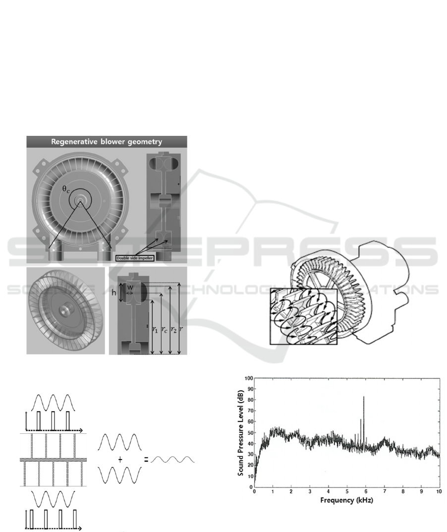
are shown in Figure 1.
In order to reduce the noise generated from
regenerative blower itself, a phase-shift cancellation
concept (Kim et al., 2014) on impeller blade
arrangement design has been implemented. Impeller
blades are equipped and arranged along angular
direction on double sides of rotating plate. Acoustic
pressure is radiating from each impeller blade in the
form of sinusoidal wave with the period of blade
pitch. If the impeller blades are arranged with
staggered type as shown in Figure 2, the acoustic
pressure radiating from impeller on one side could
be cancelled by that from impeller on another side.
Figure 1: Geometry and design variables of regenerative
blower.
Figure 2: Phase-shift cancellation concept.
2.2 Blower Noise Characteristics
The noise source considered in this research is
regenerative blower operating with high pressure
rise at low flow capacity shown in Figure 3
(Lee et
al.,
2013)
. It is widely used in various applications
including fuel cell applications. One of main
shortcomings of the regenerative blower is high
noise level. The flow inside the regenerative blower
shows typically helical-toroidal motion where fluid
rotates in and passes along the space between
rotating impeller blades and fixed side channels. It
generates two kinds of noise components such as
discrete frequency noise at BPF and the broadband
noise distributed over wide frequency range which is
produced due to inflow turbulence. Figure 4 shows
the typical pattern of noise spectrum measured from
the regenerative blower. Here BPF corresponds to
5800 Hz. The total noise level is shown as 85dB,
resulting in a 22dB reduction by applying the low
noise design concept in Figure 2. However, since the
noise level 85dB of the regenerative blower is quite
high in terms of work environment, additional noise
reduction is considered to be necessary by attaching
the perforated muffler.
Figure 3: Regenerative blower.
Figure 4: Noise spectrum of a regenerative blower.
SIMULTECH 2018 - 8th International Conference on Simulation and Modeling Methodologies, Technologies and Applications
290
3 THEORY
3.1 Sound Transmission Loss and
Insertion Loss
In order to reduce the noise generated from the
blower, a perforated muffler is attached to the
blower. The noise attenuation performance of the
muffler is evaluated in terms of transmission loss
(TL) and insertion loss (IL).
TL is defined as the logarithmic ratio between
the incident sound power
at the inlet of the
muffler and the transmitted sound power
at the
outlet of the muffler as
TL = 10
(1)
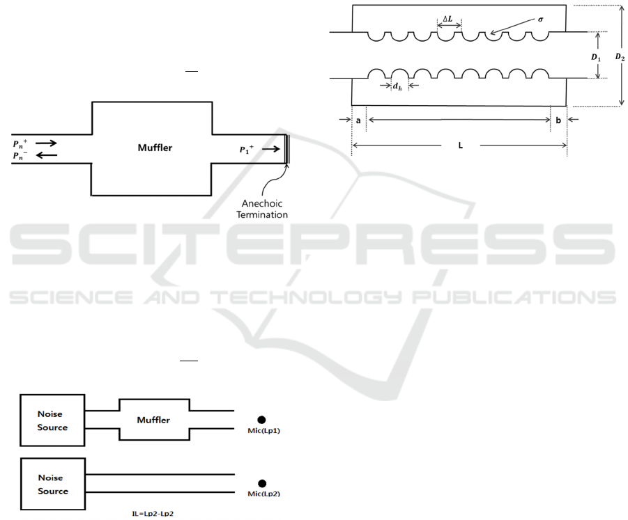
Figure 5: Layout for transmission loss.
If the area of the inlet is same as the area of the
outlet, TL can be experessed with complex
amplitude of the incident pressure
and complex
amplitude of transmitted pressuer
as
TL = 10
(2)
Figure 6: Layout for insertion loss.
IL is defined as the difference between sound
power level Lp
2
at the termination without the
muffler and sound power level Lp
1
at the
termination with the muffler installed as shown in
Figure 6. In the case of IL, it is not necessary to
install an anti-reflection terminal as shown in Figure
5. Thus it is closer to an actual value of sound loss
because all actually installed connectors related to
the blower and the muffler are considered. If the
cross sectional area of the inlet is equal to the cross
sectional area of the outlet and the outlet is anti-
reflected, TL and IL become equal. Assuming this
condition, TL has been considered to design the
muffler in this paper.
3.2 Methods to Evaluate TL
3.2.1 Transfer Matrix Method
Figure 7: Perforated muffler.
The perforated muffler is consists of parallel coupled
coaxial duct as shown in Figure 7. The two ducts are
joined together by a perforated section. The coaxial
duct has constituent sub-components with straight
parts and parts with holes, respectively. The acoustic
pressure (
,
,
,
) and volume velocity
(
,
,
,
) at the left inlet end of the coaxial duct
can be related with the acoustic pressure(
,
,
,
)
and volume velocity (
,
,
,
) at the right outlet
ends of the coaxial duct in the matrix form (Sullivan,
1978; Sullivan, 1979; Bang, 2001) as
,
,
,
,
=
[
]∏
,
,
,
,
(3)
Here
and
correspond to transfer matrices of
sub-components with straight parts and parts with
holes, respectively. means the number of the
sub-components. Considering the impedance
regarding to the relation of the pressure difference
and volume velocity through each hole, the pressure
and volume velocity at the inlet of the muffler can
be related to the pressure and volume velocity at the
outlet as
,
,
=
[
]
,
,
(4)
Development of a Perforated Diffusive Muffler for a Regenerative Blower
291
where
[
]
is the overall transmission matrix. Here
the impedance at each hole can be determined using
the empirical formula in the reference (Sullivan,
1978)
=
[6×10
+×
(
+0.75
)
] (5)
where ρ,c,
and are density of air, speed of
sound, hole diameter and acoustic wavenumber at a
given frequency, respectively. The detailed
description in the formulation of the transfer matrix
can be referred in the reference (Sullivan, 1979:
Bang 2001). From the relation in Equation (4), TL
can be evaluated as
TL = 20log
|
+
+
+
|
(6)
where
(, = 1,2) is the corresponding element
of the transfer matrix.
(= /
) and
(= /
)
mean the characteristic impedance of two duct with
section area
and
, respectively. The transfer
matrix method is generally used with the assumption
of linear sound propagation of a plane wave in the
muffler. The plane wave limit of a circular duct
corresponds to the case below the cut-off frequency
(Eriksson, 1980) with the first asymmetric mode
that is
(,)
= 0.586/
(7)
On the other hand, the first circularly symmetric or
radial mode generated at cut-off frequency is
expressed as
(,)
= 1.22/
(8)
3.2.2 Finite Element Method
Numerical simulation methods play an increasingly
important role in the design of mufflers as well as
other NVH applications. FEM offers an
advantageous combination of modelling flexibility,
computational efficiency and result accuracy.
Comparing to the boundary element method (BEM),
FEM allows modelling more complex physics of
acoustics considering multiple fluid domains, sound
propagation in a mean flow and effects of
temperature gradients in a fluid medium. FEM can
be especially used to design of mufflers to reduce
relatively high frequency noise considering the
higher modes above the cut-off frequency as well as
to design the mufflers with relatively complex
shapes.
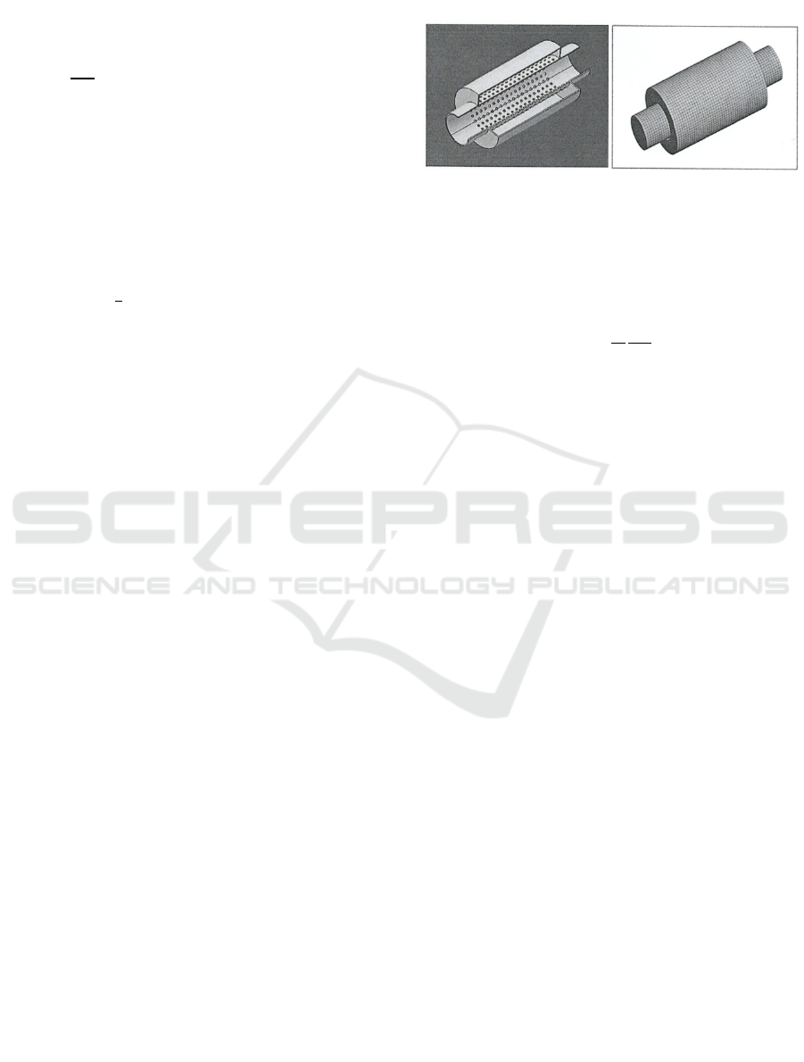
Figure 8: Structural shape and finite element model of a
muffler.
The linear wave equation for perfect gas with no
damping is expressed in terms of pressure and
speed of sound as
∇
=
(9)
At each frequency in the interested frequency range
that Equation (9) becomes Helmholz’s equation as
∇
=−
(10)
where P, mean complex pressure amplitude and
the acoustic wavenumber at the given frequency,
respectively. The three dimensional acoustic domain
of the muffler is divided into elements in Figure 8.
The variational formulation of the muffler problem
allows to formulate the discretized equation of linear
systems of algebraic equations as
[
A
]{
}
=
{
}
(11)
where
[
A
]
,
{
}
and {f} are the coefficient matrix,
sound pressure amplitude vector of nodal values and
forcing function vector of nodal values, respectively.
In the present muffler problem, {f} is only a non-
zero value at the inlet pipe according to Dirichlet
boundary condition with unit pressure.
In this study, the finite element method approach
is done by a commercial FEM program ACTRAN of
MSC software company. For more efficient way to
model perforation of the muffler, meshes on the
perforated tube are replaced by the two inner and
outer concentric surfaces with acoustic transfer
admittance. For the acoustic transfer admittance, the
transfer admittance of the perforated plate (Mechel,
2008) with the same perforation pattern of the
perforation tube is used.
SIMULTECH 2018 - 8th International Conference on Simulation and Modeling Methodologies, Technologies and Applications
292
4 DESIGN
4.1 Design Concepts
TL of the perforated muffler is dependent on design
variables such as inner diameter
and outer
diameter
, porosity σ, total length in Figure 7.
The inner diameter
is determined to be fitted to
the outer diameter of the blower. The outer diameter
is determined considering the cut-off frequencies
in Equations (7) and (8) although TL performance is
increased by increasing the cross-sectional area ratio
between the inlet and outlet ducts at frequencies
below the corresponding cut-off frequency. The
initial design length of the muffler can be
determined considering the axial modal frequencies
of the cavity itself as =
(
/2
)
( = 1,2,⋯). It
leads to decision of the initial data as
= 0.019,
= 0.06 and = 0.083.The corresponding
cut-off frequencies are
(,)
= 3320 and
(,)
= 6913.
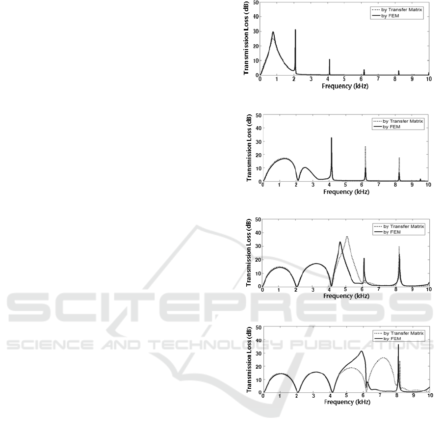
Figure 9 shows the dependence of TL on the
porosity of the muffler and also comparison of TL
result obtained by FEM with TL result obtained by
the transfer matrix method with the dependence of
the porosity. The comparison shows some
differences between two results especially above the
cut-off frequency
(,)
= 3320 as shown in
Figure 9(c) and (d). This phenomenon is shown
more clearly as the porosity is increased. It is
because TL results obtained by FEM includes the
contribution of all higher modes while the only
plane wave is considered in the transfer matrix
method.
Characteristics of the perforated muffler are
represented by the combination of the acoustic mode
of the outer tube and the effect of the resonance due
to porosity of holes in the inner perforated tube.
Those phenomena can be considered in designing
the perforated muffler. Figure 9(a) shows that at low
porosity a peak at an annular cavity resonator
resonance related to the porosity is clearly separated
from peaks of cavity axial modal frequencies in
higher frequency region. As the porosity is increased
in Figures 9(b)-(d), two peaks related the annular
cavity resonance related to the porosity and the
cavity modal frequency tend to merge and to be
strongly coupled. One can find an optimum porosity
at which two peaks merge into a single peak having
relatively broad transmission loss at a particular
frequency band that includes BPF in the nose
spectrum generated by the blower.
(a)
(b)
(c)
(d)
Figure 9: Transmission loss obtained by FEM (−) and
transfer matrix method ( ⋯) with dependence on the
porosity (σ) ∶(a) 1%, (b) 3%, (c) 11.5%, (d) 22%.
4.2 Design and Evaluation of Noise
Reduction Performance
The design concept described at section 4.1 has been
implemented to design of a perforated muffler. The
inner diameter of the muffler has been determined to
be fitted to the outer diameter of the blower as
=
0.019. The outer diameter has been determined to
be
= 0.052to increase the cut-off frequency as
(,)
= 8000 comparing with the initial cut-off
frequency
(,)
= 6913. The length of the
muffler has been determined as L=59mm to expand
Development of a Perforated Diffusive Muffler for a Regenerative Blower
293
frequency bandwidth for noise reduction comparing
with the initial length = 0.083. The porosity of
the holes has been determined to be σ = 36% to
reduce discrete frequency noise at BPF. The noise
reduction characteristics of the muffler with those
specifications are shown in Figure 10 is analyzed as
follows.
(a)
(b)
(c)
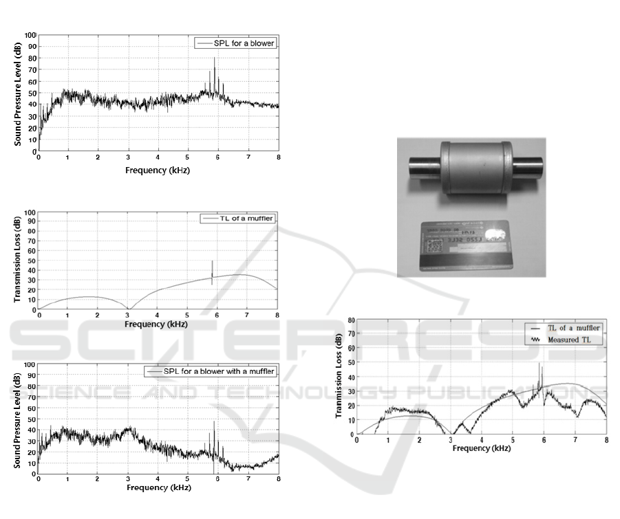
Figure 10: (a) blower noise spectrum, (b) TL of the
designed perforated muffler and (c) reduced noise
spectrum.
The regenerative blower generates the noise of
overall sound pressure level (SPL) 84 dB(A) with
the frequency spectrum shown in Figure 10(a), that
has two kinds of noise components such as discrete
frequency noise at BPF 5,800Hz and the broadband
noise distributed over wide frequency range. By
attaching the perforated muffler with TL in Figure
10(b), the overall SPL of 84 dB(A) is expected to be
reduced to 66 dB(A) in Figure 10(c) that represents
the reduced noise spectrum by attaching the
perforated muffler to the regenerative blower.
5 EXPERIMENT AND RESULTS
5.1 Performance of the Perforated
Muffler
The perforated muffler has been manufactured. It
has a relatively small size with length less than the
length of a credit card as shown in Figure 11. TL of
the manufactured perforated muffler has been
measured by comparing noise levels with and
without the muffler with the layout of the IL as
shown in Figure 6. It matches relatively well the
estimated value of TL as shown in Figure 12.
Figure 11: Perforated muffler.
Figure 12: TL of a perforated muffler.
5.2 Effects of Sound Absorbing
Material
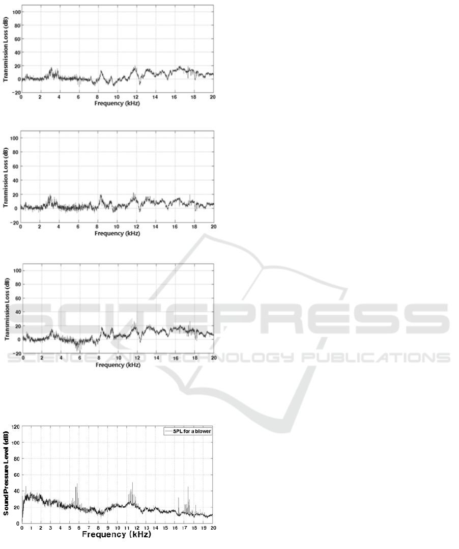
Fig. 12 shows low value of TL at 3 kHz. In order to
increase the noise absorption performance around 3
kHz, three sound absorbing materials such as PU
foam 32k, Melamine foam G, and Websuler 300G
(NYCO, 2010) are selected to insert each of those
between the coaxial ducts of the muffler. Three
perforated diffusive mufflers with those sound
absorbing materials, respectively, were manufactur-
ed. TL of each perforated diffusive muffler has been
measured and noise absorbing performance of each
material itself was separated as shown in Figure 13.
It shows that those materials have all noise
absorption effects at 3kHz and frequencies above 8
kHz.
SIMULTECH 2018 - 8th International Conference on Simulation and Modeling Methodologies, Technologies and Applications
294
(a)
(b)
(c)
Figure 13. Noise absorbing performance (a) PU foam 32k,
(b) Melamine foam G and (c) Websuler 300G.
Figure 14: Noise spectrum of regenerative blower with
attached perforated diffusive muffler.
5.3 Performance of the Perforated
Diffusive Muffler
Each muffler was attached to the regenerative
blower and noise was measured. The overall noise
levels were 65dB, 62dB and 70dB, respectively.
Figure 14 shows the noise (62 dB) characteristics of
a blower that is attached to the perforated diffusive
muffler with noise absorbing material as Melamine
form G.
6 CONCLUSIONS
A perforated diffusive muffler has been designed
and manufactured to reduce a high noise level that is
generated from a regenerative blower. The noise
consists of two components such as discrete
frequency noise component at blade passing
frequency due to rotating impellers and broadband
noise component due to turbulence produced in
blower. Main contribution into the high noise level
is due to the discrete frequency noise component. In
order to effectively reduce the noise level of
regenerative blowers, a perforated muffler has been
modelled in this paper. In order to identify important
design factors, the design parametric study has been
performed using transfer matrix method and finite
element method (FEM). It has been implemented to
design the perforated muffler that effectively
reduces the high noise level of the regenerative
blower. Effects of noise absorbing materials have
been investigated experimentally. By combining
effects of a perforated muffler and noise absorbing
material, a perforated diffusive muffler has been
designed and manufactured. Its experimental test
showed that 23 dB of noise reduction has been
achieved by attaching the muffler to the regenerative
blower. Noise level of 85dBA generated by the
regenerative blower was reduced to noise level of
62dBA.
ACKNOWLEDGEMENTS
This work was supported by the Energy Technology
Development Program of the Korea Institute of
Energy Technology Evaluation and Planning
(KETEP) granted financial resource from the
Ministry of Trade, Industry and Energy, Republic of
Korea (20172010106010).
REFERENCES
Mura, M. and Badami, M. 2012. Leakage effects on the
performance characteristics of a regenerative blower
for the hydrogen recirculation of PEM fuel cell,
Development of a Perforated Diffusive Muffler for a Regenerative Blower
295

Energy Conversion and management, 55.
Sullivan, 1979. A method for modelling perforated
muffler components. I. Theory, Journal of Acoustical
Society of America, 66(3).
Sullivan, 1979. A method for modelling perforated
muffler components. II. Applications, Journal of
Acoustical Society of America, 66(3).
Munjal, M. L., 1987. Acoustics of ducts and mufflers with
application to exhaust and ventilation system design,
John Wiley & Sons.
Wu, T. W., Wan. G. C., 1996. Muffler performance
studies using a direct mixed-body boundary element
method and a three-point method for evaluating
transmission loss. ASME Transaction, Journal of
Vibration and Acoustics, 118.
Saf., O., Erol, H., 2010. On acoustics and flow behavior of
the perforated mufflers, 17
th
International Congress on
Sound & Vibration.
Kil, H. G., Kim, K. Y. and Lee, C., 2015. Design of a
perforated muffler for a regenerative blower used in
fuel cell application, Proceedings of the 5
th
International Conference on Simulation and
Modelling Methodologies, Technologies and
Application. SCITEPRESS.
Jeon, K. H, Jang, B. Y., Lee, C. and Kil, H. G., 2017.
Development of a muffler attached to a regenerative
blower, Journal of Fluid Machinery (in Korean), 20(4).
Lee, C., Kil, H. G., Kim G.C., Kim, J. G., Ma, J.H., Chung
K.H., 2013. Aero-acoustic Performance Analysis
Method of Regenerative Blower, Journal of Fluid
Machinery, 16(2) (in Korean).
Kim, J. K, Lee, K. Y., Lee, C., Kil, H. G., 2014.
Development of a low-noise regenerative blower for
fuel cell application, Journal of Fluid Machinery, 17(2)
(in Korean).
Bang, K. H, 2001. An experiment study on the
transmission loss of perforated tube mufflers, Ph.D
Thesis (in Korean) Kookmin University.
Eriksson, L. J., 1980. Higher order mode effects in circular
ducts and expansion chambers, Journal of Acoustical
Society of America, 66(3).
ACTRAN user manual, version 13.0, MSC software
company
Mechel, F. P., 2008. Formulas of Acoustics, Springer, 2
nd
edition.
NYCO, 2010. Nam Yang Novitech CO., LTD. Catalog.
SIMULTECH 2018 - 8th International Conference on Simulation and Modeling Methodologies, Technologies and Applications
296
