
On the Use of Models for Real-time Reconfigurations of Embedded
Systems
Naima Armaoui, Mohamed Naija and Samir Ben Ahmed
Laboratory of Computer for Industrial Systems, INSAT, Tunis, Tunisia
Keywords:
Real-time & Embedded Systems, MPSoC, Co-modeling, MARTE, Reconfiguration, Performance Estimation.
Abstract:
The development of Multi-Processor System-on-Chip (MPSoC) for high-performance embedded applications
has become a major challenge for designers due to a number of crucial constraints to meet, such as functional
correctness and temporal performance. This paper presents a new process intended to support and facilitate
the co-design and scheduling analysis of high-performance applications on MPSoCs. The contribution of this
process is that it is designed to i) model the system functionality, execution architectures and allocation of
software and hardware parts using a high-level modeling language ii) verify scheduling analysis of the system
using a simulation tool and iii) offer a reconfiguration technique in order to meet constraints and preserve the
system non-functional properties (NFPs). As a proof of concepts, we present a case study consisting of a JPEG
encoder, with very promising results.
1 INTRODUCTION
The performance of materials, the explosion of functi-
onality in embedded systems and the emergence of
new architectures that is characterized by software
flexibility have introduced a new dimension to the de-
sign problem by expanding all possible configurati-
ons. Thus, it is difficult for the designer to solve the
problem of assigning tasks to the different available
execution resources while respecting non-functional
properties (such as time constraints).
To effectively address the design challenges of
multi-processors systems on chip MPSoC, multiple
ingredients need to be considered: 1) Performance es-
timation from the early stages of design would verify
compliance with non-functional constraints and vali-
date the chosen run-time configuration as a quality of
service, and 2) the use of the models transformation
via the Model Driven Engineering (MDE)(Schmidt,
2006) in the development of such systems, offers
complexity abstraction.
There are two types of reconfiguration; static re-
configuration (Angelov et al., 2005) and dynamic re-
configuration (Khalgui and Hanisch, 2011).
Our previous work (Naija et al., 2016) regards re-
configuration as any change in the structure, behavior,
or architecture of the system to adapt an external or in-
ternal change in its operating environment or context.
The reconfiguration can be software or hardware
(Khalgui and Hanisch, 2011). Software reconfigura-
tion is defined by the settings of the update task at
runtime. However, the hardware reconfiguration is
a process that adjusts the processor frequency and/or
migrates tasks originally scheduled for the software
to one or more hardware components. The recon-
figuration techniques implemented for RTES (Real-
Time Embedded Systems) can affect several models
of these: i) The functional model when there is a
change in the behavior of the system, ii) the plat-
form model in the case of a hardware resource perfor-
mance adjustment or iii) the implementation model
when there is a task migration between resources.
To address the reconfiguration of the system, our
design process proposes new techniques to model, si-
mulate and improve the behavior of such systems. In
short, we use the UML/MARTE profile (Modeling
and Analysis Real-Time Embedded systems) (OMG,
2011) and the Y-Chart approach (Combemale, 2008)
to specify applications and architectures and to as-
sociate them while considering another technique to
stop the choice of design at an early stage of the deve-
lopment cycle. This technique consists of simulating
the behavior of the system by examining the worst
execution scenario. For this, we have the tool to ad-
dress the reconfiguration of the system to meet per-
formance constraints related to the execution time.
The remainder of the paper is structured as fol-
lows. Section 2 summarizes the state of the art.
280
Armaoui, N., Naija, M. and Ahmed, S.
On the Use of Models for Real-time Reconfigurations of Embedded Systems.
DOI: 10.5220/0006867302800287
In Proceedings of the 13th International Conference on Software Technologies (ICSOFT 2018), pages 280-287
ISBN: 978-989-758-320-9
Copyright © 2018 by SCITEPRESS – Science and Technology Publications, Lda. All rights reserved

Section 3 gives a formal presentation of the Y-
Chart approach and the UML/MARTE concepts used.
Section 4 details our proposed methodology with the
reconfiguration solutions for MPSoC. Section 5 pro-
vides our case study. Finally, section 6 concludes the
paper and sketches some future work.
2 RELATED WORKS
Several approaches have been proposed in the litera-
ture for the design and verification of RTES. In this
work, we focus on approaches and design flows that
particularly deal with high-level design and verifica-
tion of reconfigurable systems.
In (Gueye et al., 2017), the authors describe an
autonomous control architecture for DPR (Dynamic
Partial Reconfiguration) based on behavioral models.
This work proposes a framework defining several
control layers and their interactions, as well as a met-
hod for systematic modeling of the reconfiguration
and configuration space of the target system class.
The scheduling layer executes the sequences of recon-
figurations by generating a table encoding the sche-
duling process based on the tasks implementations to
run. Nevertheless, there is no automated support for
the scheduling test which is an ad-hoc test.
In the same vein (Borde et al., 2009) propose a
methodology providing solutions to design and ana-
lyze critical and reconfigurable embedded systems by
leaning on both AADL and Lightweight CCM stan-
dards. Unlike this contribution, we aim to propose a
process for designing complex systems which are in-
dependent of any specific standard.
In (Krichen et al., 2012) authors propose a frame-
work to describe the software concepts of reconfigu-
rable RTES using the UML/MARTE profile. This so-
lution makes designers able to design all the system
features and verify NFP properties. However, the pro-
posed approach does not address improving system
performance when time constraints are not met.
Other efforts have been specifically tailored to re-
configurable multi-agent architectures. In (Khalgui
et al., 2011) (Zhang et al., 2015) the coordination be-
tween agents has been treated in the design to ma-
nage reconfiguration. Unlike those approaches that
only consider hardware reconfiguration, our approach
supports software and hardware reconfiguration.
3 BACKGROUND
In this section, we offer some background about Y-
Chart approach and UML/MARTE profile.
3.1 The Y-Chart Approach
The Y-Chart Approach is a methodology to provide
designers with quantitative data obtained by analy-
zing the performance of architectures for a given set
of applications (Kienhuis et al., 2001). In this appro-
ach, an application model describes the functional be-
havior of an application regardless of time and archi-
tecture. A platform defines the architecture resources
and catches their performance constraints. Mapping
is made by linking structure and system behavior to
suitable elements of the architecture. To explore de-
sign alternatives and optimize results, its mandatory
to perform transformations. As part of the quantita-
tive performance analysis, the performance of each
application/architecture combination can be evalua-
ted. In order to improve the architecture and adapt the
application(s), the designer can explore the resulting
performance numbers and try different functional and
platform customizations. This approach brings less
refinement, decreases development time, and increa-
ses the production volume.
3.2 MARTE Concepts
Among 15 concepts proposed by MARTE profile, we
work with 3 of them that are useful in our context.
We are interested in the Schedulability Analysis
Model (SAM) sub-profile to express the functional
task model. It’s designed to analyze the scheduling
of real-time systems. An early analysis of a design
model can detect real-time architectures not realiza-
ble, errors related to the temporal aspect and assess
the impact of migration to another platform. In SAM
model, the graphic description of all tasks allows ex-
pressing the access to data and at the same time data
dependencies, so the executions order of tasks.
Then, to specify all instances of the architecture,
we use the Hardware Resource Modeling (HRM)
package that allows you to model the hardware re-
sources. Another feature of this Sub-profile is sup-
port for most hardware concepts thanks to a big range
of stereotypes and once more its layered architecture.
If no specific stereotype corresponds to a particular
hardware component, a generic stereotype may ma-
tch. This is also appropriate to support new hardware
concepts of new technologies (OMG, 2011).
Also, we employ the Alloc package to specify how
the application will be placed on the platform run-
ning. The main concept is represented by the Alloca-
ted stereotype, which is used to specify associations
between the model elements of the application and
elements of architecture model.
On the Use of Models for Real-time Reconfigurations of Embedded Systems
281
4 OUR PROPOSAL
This section details the proposed design and reconfi-
guration solution used to reestablish the MPSoC fe-
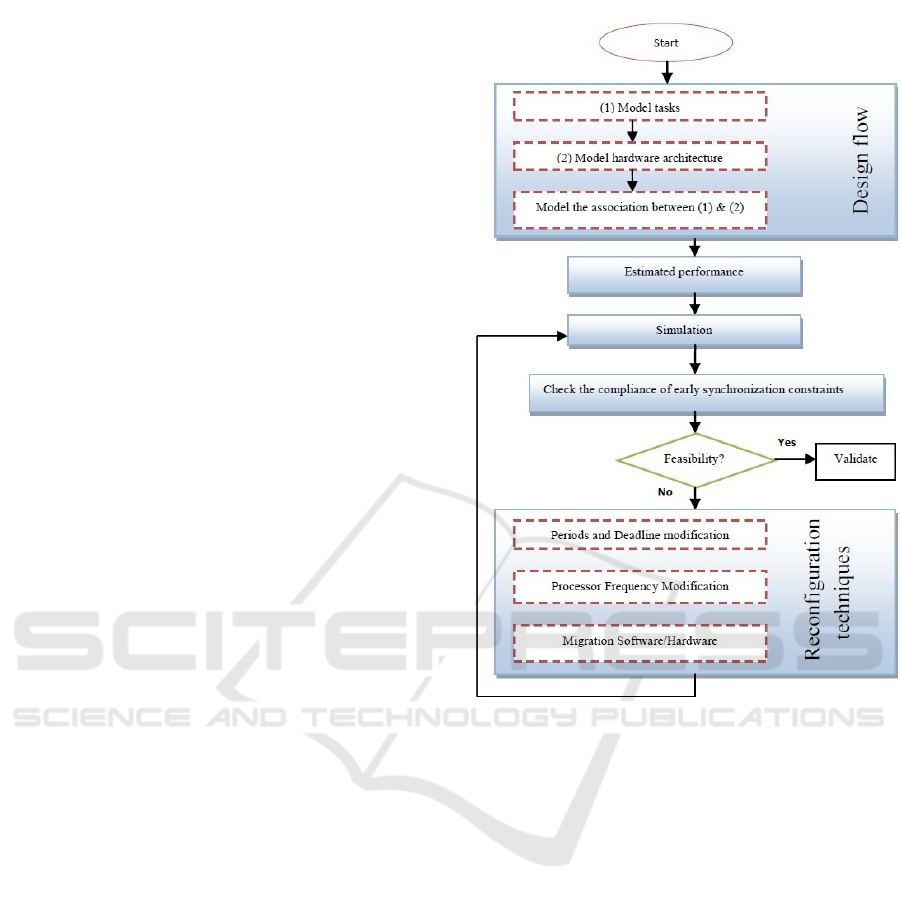
asibility. Our process is performed in a hierarchical
order as depicted in Figure 1. In this current research,
our goal is to assist in the design and reconfiguration
of real-time embedded systems on MPSoC. This pro-
cess presents a solution with three different reconfigu-
ration techniques: i) The first step consists of system
co-modeling that describe the application, the archi-
tecture, and the association between them, ii) In the
second part of our process (Estimated performance
and Simulation), we estimate the performance of the
configuration from the association step to move to the
simulation, and iii) Finally, after verifying the compli-
ance of the early synchronization constraints imposed
on the system, the current configuration will be vali-
dated if it ensures compliance with the non-functional
constraints. Otherwise, the designer must reconfigure
his system to achieve the expected performance. In
this context, we propose three reconfiguration techni-
ques of real-time embedded systems.
The following subsections give details of the inter-
mediate steps produced by our methodology and the
different proposed reconfiguration techniques.
4.1 System Co-modeling
We start our proposed approach by separately mo-
deling the different tasks of the chosen application
((1) Model tasks), the hardware architecture ((2) Mo-
del hardware architecture) and the association bet-
ween them (Model the association between (1) & (2)).
This modeling is based on the MARTE profile and the
well-known method in Y. At this design level, the fe-
atures and modeling architecture can be viewed as a
collection of components connected via ports. The
association refers to the connection of the application
elements on the hardware platform. This allows mo-
ving from a high-level description to a description of
the executable model.
4.1.1 Modeling Tasks
To model the behavioral scenario of a real-
time system, we chose the SAM sub-profile of
UML/MARTE with standard annotations. This sub-
profile helps us to detect errors related to the tempo-
ral aspect and the feasibility of architectures in real
time. In this level, we specify a periodic stream of the
functional part of the application that we stereotype
saEndtoEndFlow. Then we employ the SaStep ste-
reotype to specify the instantiated steps of the system
while respecting the functional constraints imposed at
Figure 1: Flowchart of our process.
this stage of the application. For each step, the dead-
line property is used to model the execution date of
each task.
4.1.2 Modeling Hardware Architecture
For this purpose, an abstract view of the resources of
the execution platform is assumed to have an estimate
of the execution time for the steps.
We specify, using HRM sub-profile, an abstract
view of the execution platform stereotyped hwRe-
source which defines the resources of the latter, the
connections between them and the means of commu-
nication. Thus, resources can be computational units
such as processors that are stereotyped hwProcessor
and programmable FPGA processing that is stereoty-
ped hwPLD. To be executed, a software resource must
obviously be mapped to computational units or buses.
The shared resources involved must also be described.
ICSOFT 2018 - 13th International Conference on Software Technologies
282

4.1.3 Association Modeling
In order to be executed, a software resource must ob-
viously be allocated on processors or busses. The
concept of allocation allows the designer to establish
a link between a MARTE application and platform
execution using the stereotype Allocated of the Alloc
package of UML/MARTE. Indeed, we must specify
how the application will be placed on the platform
running. This placement (Glitia and Boulet, 2008) is
both spatially and temporally. The spatial placement
is the placement of tasks on resources running. The
time is defined by the placement of a series of sche-
duling tasks allocated to the same execution resource.
4.2 Estimated Performance and
Simulation
During the design phase, it’s crucial to have some pre-
dictability and to ensure that the physical resources,
allocated to the implementation of an application’s
tasks, can check the deadlines properties. This requi-
res a full knowledge of system time constraints and
algorithmic assignment of priorities. In our approach,
the validation is performed off-line by system simu-
lation on Cheddar tool (Singhoff et al., 2004) for a
sufficient period of time called period simulation.
In a MARTE model, the design of functional be-
havior corresponds to a flow from start to finish. It
consists of a set of tasks related to each other through
their input and output ports via a link precedence.
This creates an additional cost due to the communi-
cation between tasks. In addition, the type and cha-
racteristics of each physical resource associated with
a hardware implementation must be defined. For ex-
ample, in a processor-based architecture model that
MARTE profile characterized by a speed factor and a
bus is characterized by a bit rate of data transfer by
the wordWidth attribute. From this, it’s necessary to
have an estimated time related to a high level of ab-
straction, to ensure consistency of the transition from
a purely modeling in MARTE to the Cheddar tool si-
mulation model. A good estimation of the execution
time in the worst case noted WCET, that is obtained
before the encoding and based on an analytical model.
To calculate the WCET of a task, we propose an
analytical algorithm (Algorithm 1).
4.3 Reconfiguration Techniques
Once the scheduling test is done, the next stage is to
reconfigure the system when time constraints are not
met.
Algorithm 1: Calculate the WCET of a task.
Variables :
int DataSize //The amount of data
int wW //The transfer rate on the bus provided by
the wordWidth attribute MARTE
int A1, A2, B,B1, B2 //Tasks
int T1, T2,T3, T4 , TB// The execution time of each
task
int WCET // The worst-case execution time
Require: TC = DataSize/wW //Transfer time
1.
if (A1 and A2 are connected by the relation of pre-
cedence sequential) then
if (both marks are assigned to the same compu-
ting resource) then
WCET ← T 1 + T 2
else {include the communication time}
WCET ← T 1 + T 2 + TC
end if
else if (A1 and A2 converge at B: Relationship pre-
cedence Merge OR and Join) then
if (both marks are assigned to the same compu-
ting resource) then
WCET ← max(T 1,T 2) + T B
else {include the communication time}
WCET ← max(T 1 + TC,T 2 + TC) + T B
end if
else if (A1 diverges to B1 and B2 Relationship pre-
cedence Decision OR and Fork) then
if (both marks are assigned to the same compu-
ting resource) then
WCET ← T 1 + max(T 3,T 4)
else {include the communication time}
WCET ← T 1 + TC + max(T 3,T 4)
end if
end if
We propose three reconfiguration techniques to
meet performances of the system. There are software
and hardware solutions able to reduce processor uti-
lization by changing the period in order to increase
it and therefore increasing the deadline. That is, to
have a performance behavior of a system before mis-
sing delays, better processor frequency values must
be provided. For that, the adjustment of the frequency
is suggested and the software/hardware migration of
tasks by transforming some of the application tasks in
hardware to improve its performance.
4.3.1 Periods and Deadline Modification
The first proposed technique is to modify the task pe-
riods to minimize CPU utilization, overloaded upper
U-1 to U before reconfiguration (less than or equal to
1) according to the reconfiguration scheduling policy.
On the Use of Models for Real-time Reconfigurations of Embedded Systems
283

In our case, we opt for the EDF scheduling algorithm.
The application of the feasibility test guaranteed both
respects for property CPU usage and deadlines. This
condition from (Liu and Layland, 1973) is necessary
and sufficient for the feasibility of scheduling.
Indeed, to minimize CPU usage, we calculate the
minimum period T’ arrival flow from end to end Flow
end-to-endFlow noted in MARTE in the following
formalism:
U
0
=
n
∑
i=1
C
i
/T
0
≤ 1 (1)
So,
T
0
≤
n
∑
i=1
C
i
(2)
This solution aims to increase the period and the-
refore the deadline (we work with due tasks on re-
quest). This increase will allow the overloaded pro-
cessor to complete the execution of the workflow that
is assigned to him before receiving another. After re-
configuration action, period T is replaced by the new
period T’ that minimizes the use of computing resour-
ces and ensures schedulability of the task system.
4.3.2 Processor Frequency Modification
We hope to assume that this technique expedites the
processing of functional behavior of the application.
For this, we propose to adjust the execution frequency
of the processors involved in the execution. By incre-
asing or decreasing the frequency of a processor, the
execution time of a given task will increase or decre-
ase respectively. The designer will have to opt for a
change of choice hardware upgrade.
At this early stage of the design, any change at
the architectural level is still possible as long as it can
meet the time constraints. However, the best values
of frequencies of processors are those that provide the
performance behavior of a system before missing de-
adlines. This requires computing the optimal value of
the performance of the processor frequency. This op-
timal frequency, denoted f, is the one that handles its
workload W before maturity exceeding T.
f ← W /T (3)
Note that frequency change affects energy con-
sumption.
4.3.3 Migration Software/Hardware
We seek through this technique reconfiguration, the
migration of some originally planned features in soft-
ware to one or more hardware components. It is a way
to improve application performance by transforming
some of its tasks (those that are greedy in terms of
execution time) in hardware. The choice of candidate
task for the migration is based on the percentage occu-
pancy noted processor(R name, Occ%) with R name
is the name of the resource calculation, and Occ is a
real belonging to the interval [0..100]. If two tasks
have the same percentage of processor occupancy, we
choose the one with a low exchange rate to reduce
the impact of communication. We calculate the ideal
number of tasks that must be migrated from a proces-
sor to a hardware compute unit based on CPU utili-
zation factor U. As long as this later is greater than 1,
we increment the number of tasks to migrate. The fol-
lowing algorithm (Algorithm 2) presents more details
on this technique.
Algorithm 2: Migration Software/Hardware.
Variables :
string R name // Name of the resource calculation,
int CT // Candidate task.
int nb // Number of tasks to migrate.
real RE //Rate of exchange
real Occ ∈ [0..100] .
real OccMax //the maximum percentage occupancy
nb ← 0
Require: U =
∑
n
i=1
C
i
/T
i ← 1
OccMax← (processor(R name, Occ%) of T
1
CT ← T
1
while (U ≥ 1) do
for (i = 2,i ≤ n,i + +) do
if (processor(R name, Occ%) of T
i
> OccMax
) then
OccMax←(processor(R name, Occ%) of T
i
CT ← T
i
else if (processor(R name, Occ%) of T
i
=
OccMax) then
if (RE
T
i
< RE
CT
) then
CT ← T
i
end if
end if
end for
nb ← nb + 1.
end while
5 CASE STUDY
To illustrate the design of an MPSoC according to
our approach, we opt a multimedia application and
a multiprocessors architecture to implement the ap-
plication. This methodology, based on Y-chart and
MARTE profile, is designed for performance analysis
and feasibility of scheduling via reconfiguration. So,
we choose the JPEG image compression standard as
ICSOFT 2018 - 13th International Conference on Software Technologies
284
a case study, where it works on large amounts of data
by making calls to process high-performance compu-
ting.
5.1 Co-modeling
5.1.1 Modeling Features of JPEG
The JPEG compression process (Wallace, 1992), il-
lustrated in Figure 2, accepts as input a raw image
from an input device (camera). The first stage of com-
pression is to cut the image into blocks (8 * 8) or 64
pixels. Each block of pixels is applied to a processing
luminance and chrominance color. After that, a DCT
transform is applied to each block of pixels in order to
express the image information in terms of frequency
and amplitude. The stream passes through the com-
pression result by the quantization step which is the
basis of the compression. Finally, the application of
the coding to the resulting Huffman matrix quantiza-
tion step leads to a compressed image.
Figure 2: JPEG compression flow.
Our design methodology that specifies various
parts of a system (application, architecture, and asso-
ciation), is done in the Eclipse environment that bene-
fits from the integrability of the Papyrus editor. This
editor uses UML as modeling language and allows the
addition of profiles to enrich the model with specific
details in a design field. Thus, we present the mo-
deling, as a high level of abstraction, of the characte-
ristics of the JPEG algorithm using the SAM package.
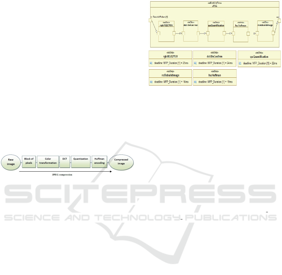
In this context, we specify (see Figure 3) perio-
dic flow from end to end application level (or functi-
onal), stereotyped saEndtoEndFlow called JPEG. In-
deed, the five instances of steps: rgb, dct, qu, hu and
re are stereotyped SaStep and are executed sequenti-
ally (each elementary behavior depends on that which
precedes it). For example, the first instance of dct of
component DisCoST can be activated before the first
instance rgb of component RGB2YUV is processed.
Similarly, the other instances (qu, hu, re) are activa-
ted. This allows us to infer functional constraints im-
posed at the application level. These constraints re-
present an execution order of tasks. For each step, the
date for execution is indicated by the deadline pro-
perty. In addition, we use the MARTE profile to add
details of the specification, including the input port
with the direction in (raw image) and the output port
with the out direction (compressed image).
Figure 3: Modeling features of JPEG in MARTE.
We want to have a rate of compression of 15 fra-
mes per second in JPEG image size (256 x 256) pixels
encoding, i.e., the maximum time to encode an image
is 0066 seconds.
5.1.2 Architecture Modeling
In order to implement the algorithm described above,
we consider a hardware architecture consisting of
two processors and a programmable processing unit
FPGA, which communicate with each other through
a shared memory via a bus located between the exe-
cution and memory units. The three computational
units, with rights writing and reading memory com-
petitors, are defined to address the different functional
components of the JPEG application. The cpu 1 bo-
dies and cpu 2 are stereotyped hwProcessor and the
programmable FPGA processing is stereotyped hw-
PLD. The memory model instantiated by the hw-
Memory stereotype is defined as a shared storage re-
source and recovery of data and program instructions.
The role of the transmitter (the instance of Camera
component) and the receiver (the instance of Screen
component) is to produce and consume pixels. They
are respectively stereotyped hwSensor and hwActua-
tor. The communication between different physical
resources requires the stereotype hwBus of compo-
nent Bus. All instances of the architecture compo-
nents are specified with concepts in HRM MARTE
profile. Figure 4 illustrates, in a high level of ab-
straction, the architecture model of the JPEG appli-
cation.
5.1.3 Modeling Association
The concept of allocation allows the designer to esta-
blish a link between a MARTE application and plat-
form execution. In MARTE, this concept of alloca-
tion is expressed by the Allocate stereotype. Figure
5 shows an example of an association of JPEG appli-
cation on different execution resources through ste-
On the Use of Models for Real-time Reconfigurations of Embedded Systems
285
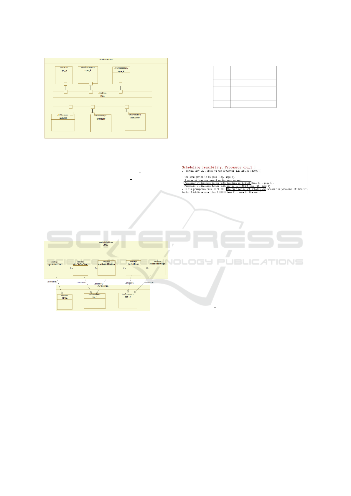
Figure 4: Architecture modeling in MARTE.
reotyped connectors Allocated: rgb first step is as-
signed to the programmable FPGA computing, dct
and qu steps that are associated with cpu 1 processor,
hu and re steps are assigned to cpu 2 processor. A
good combination of software and hardware can sig-
nificantly reduce the execution time of the application
features and respect the constraints dependencies to
ensure the proper functioning of the system. Thus,
for MPSoC architecture, several choices of associa-
tion can be considered. In this part of the process of
modeling the designer’s experience plays a key role
in the consistency of spatial and temporal placement.
Figure 5: Modeling association.
5.2 Estimated Performance
We estimate time-related perforations in this case
study using the steps of the performance estimation
algorithm (Algorithm 1). As a configuration, we
chose to combine all cpu 1 functional tasks. This
choice is motivated by the lack of parallelism with
task performance and reduced overhead costs due to
the communication between CPUs. Table 1 shows an
estimate of tasks number times in clock cycles.
Table 1: Estimations of tasks in cycles.
Step Duration (cycle)
rgb 7714816
dct 7387136
qu 7086080
hu 5636096
re 4704256
5.3 Simulation and Reconfiguration
We consider this section to analyze the system beha-
vior on the Cheddar tool dedicated to the check of
properties deadlines. Figure 6 offers a simulation re-
sult for checking the configuration from the associa-
tion step.
Figure 6: First Cheddar simulation.
We can see that the system does not meet these
time requirements and therefore it’s not schedulable.
One way to improve the performance of an on-board
MPSoC system is to reconfigure it in order to adapt to
its environment without any perturbation. We propose
in this context 3 reconfiguration techniques which are
already detailed in Subsection 4.3. There are able to
reduce the CPU utilization noted U factor, given by
the following formula
∑
n
1
C
i
/T
i
, with C
i
the cost of
task i and T is her period. When U is greater than 1,
said the processor is overloaded. We carry our testing
early in the design phase, and therefore any change in
the application settings or architectures is allowed.
In this case study, we opt for a frequency modifi-
cation of cpu 1 execution to reconfigure our system.
We seek the frequency that ensures the implementa-
tion of all tasks durations total clock cycles 32528384
processor in a period of 0.066s. The optimal fre-
quency is 493MHZ instead of 300MHZ. This requires
recalculation of the new task durations. We also recal-
culate the temporal parameters of tasks, such as the
date of revival and maturity, to consider all the prece-
dence constraints. Table 2 summarizes the new tem-
poral parameters of tasks. A new simulation shows
that the studied system is now schedulable (Figure 7).
6 CONCLUSIONS
In this paper, we have proposed a new process for de-
signing complex embedded systems with hard real-
time constraints. Our solution is integrated into the
ICSOFT 2018 - 13th International Conference on Software Technologies
286
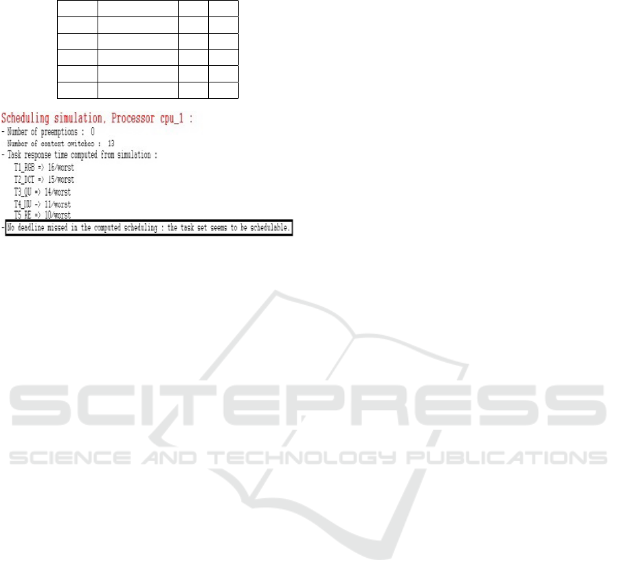
Table 2: Estimated times of new tasks.
Step WCET(ms) ri Di
Rgb 16 0 66
Dct 15 16 50
Qu 14 31 35
Hu 11 45 21
Re 10 56 10
Figure 7: Second simulation time constraints with the
Cheddar tool.
software life-cycle since the very beginning that auto-
mates the transition from functional model to design
model. It’s based on modeling the system functio-
nality, execution architectures and allocation of both
parts using the MARTE profile. After the calculation
of the execution time through a proposed algorithm,
the scheduling test is performed using the Cheddar
tool. In addition, we developed 3 reconfiguration
techniques in order to preserve system NFPs at a high
abstraction level. Such approach provides a guideline
for the designer to find an implementable concurrency
model describing a real-time application. We showed
the effectiveness of our approach through a case study
of high-performance applications on MPSoCs.
Now, to extend the current research, we are imple-
menting the proposed solution in a practical system
based on a multi-agent architecture. Also, we will ad-
dress the placement issue, during the reconfiguration
step, considering the uncertainty of the execution time
of each task and the availability of resources.
REFERENCES
Angelov, C., Sierszecki, K., and Marian, N. (2005). Design
models for reusable and reconfigurable state machi-
nes. In International Conference on Embedded and
Ubiquitous Computing, pages 152–163. Springer.
Borde, E., Ha
¨
ık, G., and Pautet, L. (2009). Mode-based
reconfiguration of critical software component archi-
tectures. In Proceedings of the Conference on Design,
Automation and Test in Europe, pages 1160–1165. Eu-
ropean Design and Automation Association.
Combemale, B. (12 aot 2008). ng
´
enierie dirig
´
ee par les
modles (idm).
Glitia, C. and Boulet, P. (2008). High level loop transforma-
tions for multidimensional signal processing embed-
ded applications. In International Symposium on Sy-
stems, Architectures, MOdeling, and Simulation (SA-
MOS VIII).
Gueye, S. M.-K., Rutten,
´
E., and Diguet, J.-P. (2017). Auto-
nomic management of missions and reconfigurations
in fpga-based embedded system. In Adaptive Har-
dware and Systems (AHS), 2017 NASA/ESA Confe-
rence on, pages 48–55. IEEE.
Khalgui, M. and Hanisch, H.-M. (2011). Reconfiguration
protocol for multi-agent control software architectu-
res. IEEE Transactions on Systems, Man, and Cyber-
netics, Part C (Applications and Reviews), 41(1):70–
80.
Khalgui, M., Mosbahi, O., Li, Z., and Hanisch, H.-M.
(2011). Reconfiguration of distributed embedded-
control systems. IEEE/ASME Transactions on Mecha-
tronics, 16(4):684–694.
Kienhuis, B., Deprettere, E. F., Van der Wolf, P., and Vis-
sers, K. (2001). A methodology to design programma-
ble embedded systems. In International Workshop on
Embedded Computer Systems, pages 18–37. Springer.
Krichen, F., Hamid, B., Zalila, B., and Jmaiel, M. (2012).
Design-time verification of reconfigurable real-time
embedded systems. In High Performance Compu-
ting and Communication & 2012 IEEE 9th Internati-
onal Conference on Embedded Software and Systems
(HPCC-ICESS), 2012 IEEE 14th International Con-
ference on, pages 1487–1494. IEEE.
Liu, C. L. and Layland, J. W. (1973). Scheduling algo-
rithms for multiprogramming in a hard-real-time en-
vironment. Journal of the ACM (JACM), 20(1):46–61.
Naija, M., Bruel, J.-M., and Ahmed, S. B. (2016). To-
wards a marte extension to address adaptation me-
chanisms. In High Assurance Systems Engineering
(HASE), 2016 IEEE 17th International Symposium
on, pages 240–243. IEEE.
OMG, O. M. G. (2011). A uml profile for marte: Modeling
and analysis of real-time embedded systems.
Schmidt, D. C. (2006). Model-driven engineering.
Computer-IEEE Computer Society-, 39(2):25.
Singhoff, F., Legrand, J., Nana, L., and Marc
´
e, L. (2004).
Cheddar: a flexible real time scheduling framework.
In ACM SIGAda Ada Letters, volume 24, pages 1–8.
ACM.
Wallace, G. K. (1992). The jpeg still picture compression
standard. IEEE transactions on consumer electronics,
38(1):xviii–xxxiv.
Zhang, J., Khalgui, M., Li, Z., Frey, G., Mosbahi, O., and
Salah, H. B. (2015). Reconfigurable coordination of
distributed discrete event control systems. IEEE Tran-
sactions on Control Systems Technology, 23(1):323–
330.
On the Use of Models for Real-time Reconfigurations of Embedded Systems
287
