Strategy for Reduction of the Negative Effects of Circumferential
Flow Irregularity in Axial Compressor
Aleksandr Ermakov, Grigorii Popov, Daria Kolmakova and Vasilii Zubanov
Insitute of Engine and Power Plant Engineering, Samara University, Samara, Russia
Keywords: Intermediate Pressure Compressor, Flow Irregularity, Vibrations, Annular Frame, CFD, Optimization.
Abstract: Gas flow nonuniformity is one of the main sources of rotor blade vibrations in the gas turbine engines. Often,
the source of the flow circumferential nonuniformity are the annular frames, located in the flow passage of
the engine. This leads to the increased dynamic stresses in rotor blades and consequently to the blade
destruction. The goal of the research was to find an acceptable method of reducing the level of gas flow
nonuniformity. Thus, this study gives the ideas about methods of improving the flow structure in gas turbine
engine. It allows the selection of the most suitable method for reducing gas flow nonuniformity.
1 INTRODUCTION
Gas flow circumferential non-uniformity is one of the
main sources of oscillation of turbomachinery rotor
blades (Ivanov, 1983; Vorob'ev., 1988; Cohen etc.,
1996). The flow circumferential irregularity is caused
by various factors: the axial asymmetry at the
turbomachinery inlet; the presence of guide vanes
(GV) and nozzle blades (NB) in the turbomachinery
flow path; the influence of the structural elements
(struts and bearings); bypass system operation and air
bleeding; the operation of fuel nozzles of combustion
chambers; the deformation of power casings; the
buckling of the flame tubes of combustion chambers.
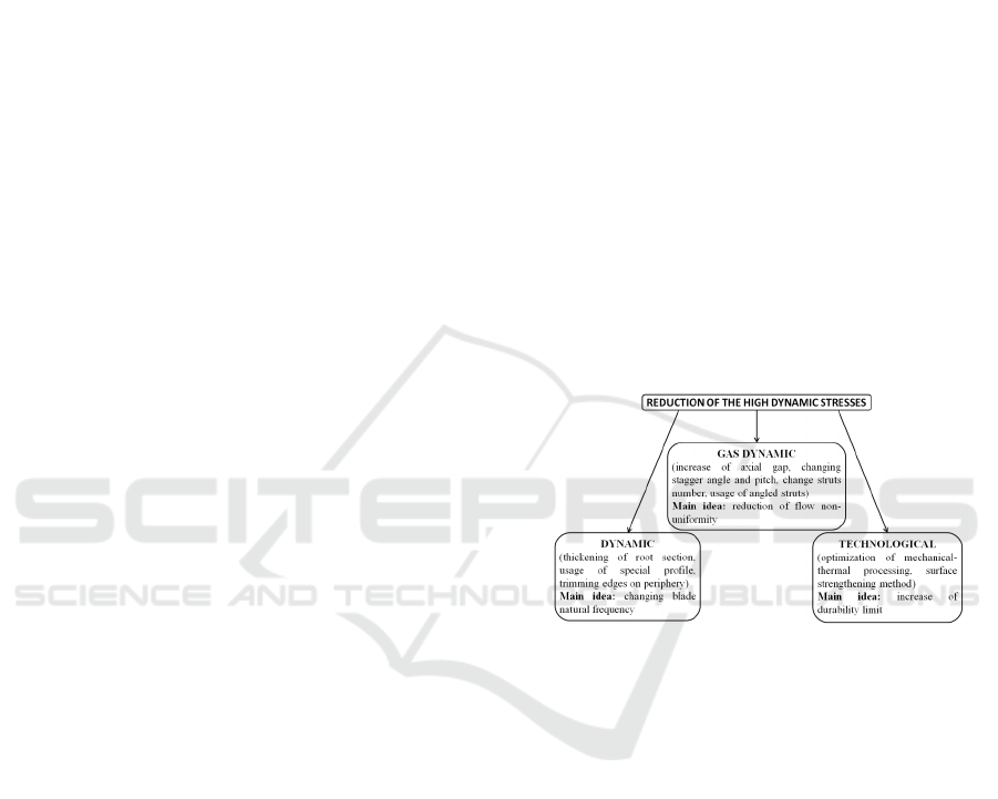
Several methods are used in practice to reduce
high dynamic stresses: dynamic methods, gas
dynamic methods and technological (Figure 1)
(Ivanov, 1983; Birger etc., 1993; Logan, 2003).
Each method has its advantages and
disadvantages, as well as the range of applicability.
Methods that suggest design changes are impossible
to apply to already designed engines.
However, it is possible to test the effectiveness of
the proposed methods of dynamic stresses reduction
without resorting to expensive and long experimental
studies. For these purposes, it is possible to use CFD
(Respondek, 2010) of the work processes occurring
in the engine as a preliminary verification step.
The purpose of the research was to evaluate the of
various methods and to indicate the most appropriate
approaches for solving specific problems.
Figure 1: Classification of different methods to reduce high
dynamic stresses in rotor blades.
2 MOTIVATION
The motivation for this research was the real-life
destruction problem of the fifth stage rotor blades of
the intermediate pressure compressor GTE NK-36ST
(RW5 in Figure 2).
The reason of rotor wheel blades’ destruction is
the flow circumferential irregularity, which arises
from the presence of middle annular frame struts in
the GTE flow path. Struts have different profile
thickness and distributed with different angular
displacements relative to each other (Figure 3). Struts
are the cause of the appearance of local zones of high
pressure, which propagate upstream through the
cascade of GV5 fixed blades. Passing through these
zones, rotor wheel blades of the fifth stage experience
dynamic effect, leading to their forced oscillations
and high dynamic stresses (Figure 4).
144
Ermakov, A., Popov, G., Kolmakova, D. and Zubanov, V.
Strategy for Reduction of the Negative Effects of Circumferential Flow Irregularity in Axial Compressor.
DOI: 10.5220/0006887501440150
In Proceedings of 8th International Conference on Simulation and Modeling Methodologies, Technologies and Applications (SIMULTECH 2018), pages 144-150
ISBN: 978-989-758-323-0
Copyright © 2018 by SCITEPRESS – Science and Technology Publications, Lda. All rights reserved
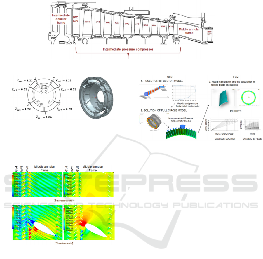
Figure 2: The diagram of investigated compressor flow path.
Figure 3: The appearance of middle annular frame.
Because of this, the fifth rotor wheel (RW) blades
in the original design have anti-vibration segments.
However, such a solution has several shortcomings
(Cumpsty, 2004).
a) b)
Figure 4: Mach number (a) and pressure (b) fields.
Thus, the aim of the work was the search of an
alternative approach for reduction of dynamic
stresses level in the fifth rotor wheel blades of
intermediate pressure compressor (IPC). For further
research, the fifth-stage rotor blades were modeled
without anti-vibration segments.
3 METHOD OF DYNAMIC
STRESSES CALCULATION
At the initial stage of the work, the method of
dynamic stresses calculation in the fifth rotor wheel
blades of IPC was developed (Figure 5).
Figure 5: Scheme of method for calculation compressor
rotor blades forced oscillations.
Stage 1. CFD-simulation of IPC sector model on
the main modes of GTE operation. The sector is one
blade channel of blade row, the lateral boundaries of
which are imposed by boundary conditions of
periodicity. The IPC sector model consists of the
intermediate frame domain, the domains of all IPC
blade rows, the middle frame domain and the inlet
guide vane of high pressure compressor (HPC IGV).
When transmitting the flow parameters between
domains, the Mixing Plane interface is used
(NUMECA, 2008), averaging the flow parameters in
the circumferential direction. The purpose of this
calculation is to determine the flow parameters
distribution (total pressure, total temperature, flow
angle) along the flow path height in the cross section
behind the RW of the IPC fourth stage, as boundary
conditions for subsequent calculations.
Stage 2. The CFD modelling of full circle model
will allow to detect the presence of gas flow
circumferential irregularity, which arises from the
nonuniformly located struts of different thickness
along the circumference.
This model consists of GV4, RW5, GV5 of IPC,
middle annular frame and HPC IGV domains. Gas
dynamic load acting on all blades of the fifth stage
rotor wheel is determined in this calculation.
Creation the grid of finite volumes of the full
circle model was carried out in AutoGrid5
(NUMECA, 2008). Parameters of finite volume grids
and computational models tuning were chosen
Strategy for Reduction of the Negative Effects of Circumferential Flow Irregularity in Axial Compressor
145

according to the recommendations given in papers
(Matveev etc., 2014; Popov etc., 2014). The
computational models were verified in studies
(Kolmakova etc., 2014; Ermakov etc., 2014) in
assessing the vibration level of rotor blades. This
indicates the reliability of the calculations performed
in the study described in this article.
Total pressure and temperature, and inlet flow
direction at the inlet, which were obtained from the
sector model calculation at the previous step
(Ermakov etc., 2014); static pressure at the outlet of
the computational model were set as the boundary
conditions for the full circle model.
To transfer parameters between the rotating and
fixed domains, the standard Frozen Rotor interface
was used without their averaging in the
circumferential direction (ANSYS, 2017).
Stage 3. Determination the values of exciting
harmonics amplitudes of the load, as well as dynamic
stresses arising in the RW5 blade. For this purpose, in
the APDL programming language, the program that
imports the load distribution from the finite volume
blade row model in CFX into the finite element blade
row model in Ansys Mechanical APDL, were written.
The gas load, which has a complex character of the
distribution along the circumference, was represented
as a sum of the harmonics components. Each
harmonics component represents a load waves chain
that locate along the flow path circumference. The
load rotates at angular velocity. Thus, the
circumferential stationary inhomogeneity of the gas
flow for a rotating rotor wheel is equivalent to the
action of an infinite set of exciting harmonics, each of
which is a load chain of backward running waves
performing harmonic oscillations in time.
The load is expanded in Fourier series along the
similar blades’ nodes and is represented in the form
of a backward running wave. Campbell diagram is
used to determine the most dangerous operating
modes of the engine, and the most dangerous
harmonics. The dynamic stresses are calculated only
with the most dangerous harmonic.
4 METHODS OF REDUCTION
THE DYNAMIC STRESSES
4.1 Detuning the Rotor Blade from the
Dangerous Harmonics
IPC testing without shroud segment of RW blades
(the blade without shroud segment is a standard blade
airfoil without anti-vibration segment) was carried
out by JSC "Kuznetsov".
The experimental investigations were carried out
using a cold test rig for the IPC with standard pressure
at the inlet and middle annular frame at the outlet.
Two types of the tests were conducted. Strain gauges
were installed at five rotor blades in the first case and
at 12 rotor blades in the second test case (total number
of rotor blades was 84). The maximum rotor speed,
during the tests was the speed at which resonance
occurs with the most dangerous harmonics.
These tests revealed the destruction of the IPC
fifth stage rotor blades at resonance with the 7th and
12th harmonics. Figure 6 shows the histogram of the
exciting load amplitude distribution, calculated using
the method described in clause 3. The average value
on the blade surface that is calculated by adding the
amplitudes of the harmonics in each node and
dividing by the number of nodes is referred to the
mean amplitude. Similar calculations are performed
for all blades in the fifth blade row.
As can be seen from Figure 6, the 12th harmonic
has the highest amplitude (harmonics from 7 to 14 fall
into the region of GTE operating modes).
Figure 6: Level of the amplitudes of the exciting harmonics.
An attempt to turn out from the most dangerous
7th harmonic, and to increase the flexural strength of
the airfoil blade to reduce the dynamic stresses at
resonance with the 12th harmonic, was made at JSC
"Kuznetsov". For this purpose, a special Shvarov's
profile was used. The shape of the suction side
surface coincides with the initial profile; however, the
pressure side surface is convex. This profile shape
allows to significantly reduce the flexural stresses in
the airfoil. Finite element harmonic analysis showed
a double decrease in the dynamic stresses of blade
airfoil at the resonance with the 12th harmonic
(Figure 7). Increase of IPC efficiency was about 0.5%
for the compressor variant with Shvarov’s profile on
SIMULTECH 2018 - 8th International Conference on Simulation and Modeling Methodologies, Technologies and Applications
146
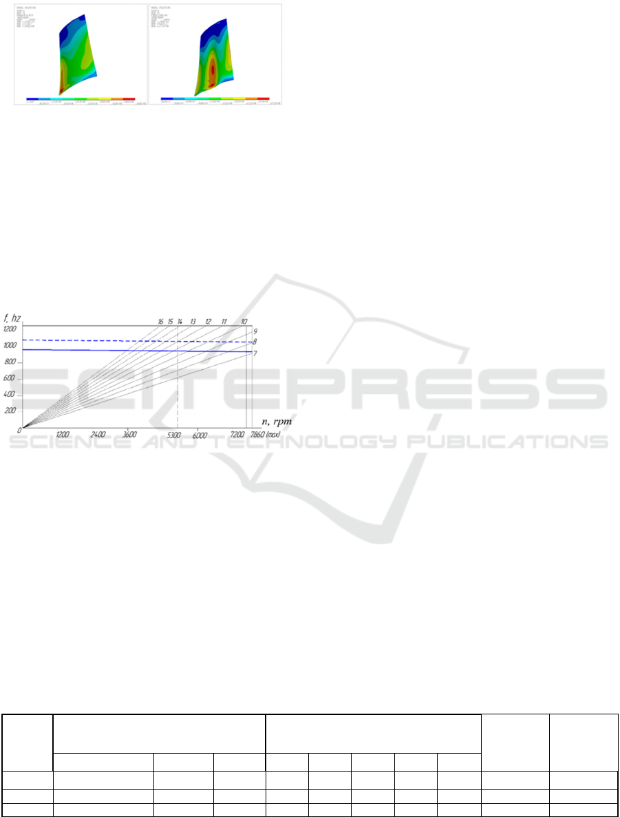
the rotor blades compare to the compressor with
shrouded blades.
Figure 7: Equivalent stresses at the resonance in RW5 blade
(original is on the left, Shvarov's profile is on the right).
Figure 8 shows the Campbell diagram for the 5th
rotor wheel with the original unshrouded rotor blade
and with blade with Shvarov's profile. Thus, the use
of blade with the special Shvarov's profile allows to
significantly reduce the dynamic stresses in the
airfoil, as well as to turn out from dangerous
operating modes. For the blades with Shvarov’s
profile the strongest seventh harmonic is out of region
of the engine operating modes (Figure 6).
Figure 8: RW 5 resonance diagram (--- Blade with
Shvarov's profile, - original blade).
Using the blades with special Shvarov's profile
allow to reduce the level of dynamic stresses by 1.8
times. This result was confirmed experimentally
during strain-gauging at JSC "Kuznetsov". The
stresses were measured using heat-resistant strain
gauge, located on the surface of the blade pressure
side. The single amplitudes were estimated. However,
this reduction was not enough to eliminate the
problems of blade destruction. It is necessary to
influence not only the blades shape, but also the gas
flow circumferential irregularity. In further
researches, we used the blade with Shvarov's profile.
4.2 Design Change
One of the methods of reduction the gas flow
circumferential irregularity in front of the struts is the
use of guide vane with a different pitch along the
circumference and different stagger angle of the GV
blades (Sladojević etc., 2007; Yang etc., 2012). This
method allows to redistribute the flow between
various blade channels and to regulate the position of
high pressure zones (Saren, 1984).
Parametric model of IPC fifth stage GV was
created to implement the method. All GV blades were
divided into 7 groups, according to the location of the
7 struts. Angles and pitch changes occurred within
each group. The key factor was the minimum number
of variable blades.
For the GV5 blades located in the symmetry plane
of the strut, the first and the last blades in the group,
the stagger angle does not change. The change of
blades stagger angles within the groups was carried
out according to a linear law. The blades located on
opposite sides of the strut symmetry plane rotate in
opposite directions, relative to the initial position
(Figure 9). The blades located closer to the strut rotate
a larger angle. If the stagger angle increases, the sign
"+" stands in front of the angle, the sign "-" means
decreasing stagger angle. All angles are measured
from the leading edge plane.
In the case of pitch change, the number of
changeable blades was not limited. Different pitch
was set in the range -0.35 ... + 0.35 of the pitch. The
sign "-" means that in the strut area the pitch between
the blades decreased, and the sign "+" - that the pitch
increased. The number indicates the maximum
increase (decrease) of the pitch between the blades in
the group in relative values from the nominal pitch
with uniformly arranged blades. When different blade
pitches are introduced in groups, the position of the
extreme blades groups did not change. The law of
pitch change is also linear.
In total, 10 variants of the GV5 configuration with
different angles and pitches were tested. Table 1
shows same of them. Variant 1 corresponds to the
original version of the IPC without an anti-vibration
segment on the RW5 blades with Shvarov’s profile.
Table 1: The results of the parametric IPC model calculation.
Variant
number
Parameter of different stagger angles,
maximum stagger angles (number of blades)
for the groups:
Parameter of alternating blade pitch for the
groups:
Number of
variable
blades
Dynamic
stresses
MPa
2, 5, 6 1, 3, 7 4 (3) 1, 7 2, 6 3 4 5
1 0 0 0 0 0 0 0 0 0 86.7
4 3 (6) 3 (6) 3 (8) 0.3 0.3 0.3 0.3 0.3 42 31.877
9 6 (2) 6 (2) 6 (2) 0 0 0 0 0 14 46.737
Strategy for Reduction of the Negative Effects of Circumferential Flow Irregularity in Axial Compressor
147
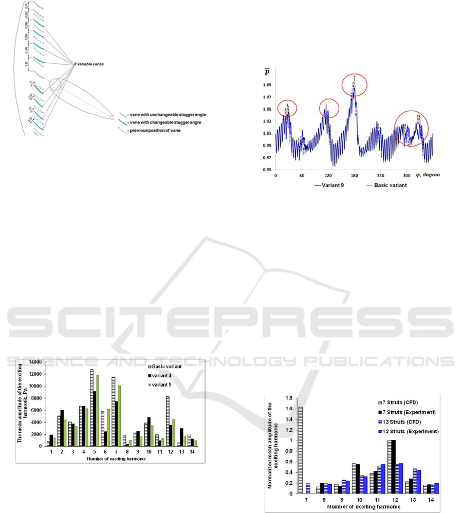
Figure 9: The diagram of GV blades rotation.
The analysis of the obtained results has shown that
it is possible to achieve a significant reduction in the
level of the exciting harmonics acting on the RW5
rotor blades, and, consequently, the level of dynamic
stresses with the help of different angles and pitches.
For example, variant 9 allows to reduce the
dangerous harmonic amplitude by almost 2 times. In
this variant of the GV5 configuration the number of
changeable blades is 14 (a total of 76 blades). Variant
4 allows to obtain the greatest dynamic stresses
decrease, however the number of changeable blades
will amount to 42, which is more than half of the total
number.
Figure 10 shows the mean of average exciting
harmonics amplitudes for the original compressor
version, GV variant 4 and GV variant 9.
Figure 10: The mean of exciting harmonics amplitudes
acting on RW5.
From a gas dynamic point of view, the positive
effect of different angles and pitches on the dynamic
stresses value can be explained by the following. Due
to redistribution of the flow, its structure becomes
more homogeneous, with smaller high pressures
areas. In addition, the pressure peaks values behind
the 5th rotor wheel is also markedly reduced (Figure
11).
Thus, the introduction of GV of different angles
and pitches can reduce the gas flow circumferential
irregularity and dangerous harmonics amplitude.
However, the use of this method leads to a
complication of production technology. GV blades in
this case will have to be manufactured by
nonuniversal technologies. In addition, due to the
change in the blades pitch, it will be necessary to
develop a new technology for grooving.
Figure 11: Graphs of relative static pressure variation for
basic compressor variant and variant 9.
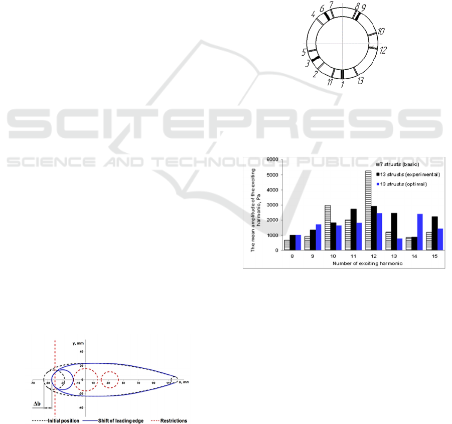
4.3 Modification of Frame Design
Experimental 13-struts annular frame was made by
JSC ''Kuznetsov'' to reduce the resonant stresses level
in the IPC fifth stage. Variable stresses level at
resonances with the strongest 12th harmonic in the
test with 13-struts annular frame decreased
approximately 2 times. Experimental 13-struts
annular frame calculation using the method described
above confirmed the decrease in the average
amplitude of the 12th harmonic (Figure 12) by 1.8
times. This fact is another confirmation of the
reliability of the developed methodology.
Figure 12: Comparison of excitation amplitudes of
harmonics of the basic 7-struts and 13-struts annular frame
obtained in experiment and CFD calculation.
Comparison of normalized mean harmonic
amplitudes of the basic 7-struts annular frame and
experimental 13-struts annular frame obtained in
experiments and by CFD is shown in Figure 13. The
calculation results were converted into relative values
by considering the mean amplitude of 12th harmonic
of base 7-struts frame as 1 to compare calculation data
SIMULTECH 2018 - 8th International Conference on Simulation and Modeling Methodologies, Technologies and Applications
148
with experimental results.
Experimental 13-struts annular frame proposed by
JSC "Kuznetsov" specialists allowed to decrease the
resonant stresses in the fifth stage rotor blades and to
exclude the anti-vibration segment. However, in this
annular frame in addition to increasing the struts
number, their thickness was reduced. This is critical
towards to the struts through which the various engine
systems of communications pass. Therefore, the use
of this frame on the engine is impossible.
For this reason, it was decided to develop a new
design of 13-struts annular frame with saving the
position and required cross-sections in the struts No.
1, 2, 4, 5 of 7-struts with engine systems.
When designing the new annular frame, all the
previous modifications of the compressor were not
considered (different stagger angles and pitches)
except the implementation of Shvarov’s profile on the
rotor blades of the fifth stage.
It was agreed that the development of new annular
frame design would be carried out using optimization
methods implemented in the IOSO software package
(Egorov etc., 2002; Sigma Technology, 2017). Since
the use of large-scale 3-D model during optimization
requires significant computational resources and
time, it was decided to use surrogate struts models.
With this approach, each strut is represented as a
pressure peak, which the strut causes in the axial gap
between RW5 and GV5. The shape of the peaks is
determined by the geometric parameters of the struts,
and their location in the circumferential direction is
the arrangement of the corresponding struts.
Additional research was carried out (Kolmakova
etc., 2015) using struts parametric models (Figure 13)
to determine the relationship between the struts
geometric dimensions and the peaks’ shape. These
models allowed to change the struts design taking into
account the existing limitations.
As a result, the obtained data array allowed to
derive equations for each strut type, reflecting the
dependence of pressure peaks’ height on the position
of the strut leading edges relative to the outlet edges
of GV blades located upstream.
The found equations after verification were used
to search for a new annular frame design using IOSO.
Figure 13: Strut parametric model.
The optimization problem is the following. Struts
position and the values of the shift of the strut leading
edges are used as variable parameters. Optimization
criteria were to reduce the amplitude values of 12th
and 10th harmonics (the second largest after 12th).
Pareto set was obtained which is the compromise
between the decrease in 12th and 10th harmonics. The
point of the Pareto set, which gives the maximum
decrease in the 12th harmonic amplitude, was chosen
as a point for further research.
The annular frame configuration corresponding to
the selected point of Pareto set is shown in Figure 14.
For this configuration, a CFD simulation was
performed using the method described in Section 3 of
this article. As a result, the amplitude of the 12th
harmonic was reduced (Figure 15).
Figure 14: Optimized 13-struts annular frame.
Thus, the change in the annular frame structure
makes it possible to significantly reduce the exciting
harmonics amplitudes.
Figure 15: Comparison of exciting harmonics amplitudes of
the original 7-struts, 13-struts frame by JSC ''Kuznetsov''
and optimized 13-struts annular frame.
5 CONCLUSIONS
Several approaches to increase the dynamic strength
of GTE compressor rotor wheels were developed.
Each of the proposed approaches, possessing a set of
advantages and disadvantages, allowed to achieve the
set goal which was to reduce the dynamic stresses
level in rotor blades. Also, the following aspects can
be noted as the obtained research results:
Strategy for Reduction of the Negative Effects of Circumferential Flow Irregularity in Axial Compressor
149

1) The calculation method of dynamic stresses
caused by the flow circumferential irregularity
is developed;
2) The use of special Shvarov's profile on the
RW5 blades makes it possible to reduce the
dynamic stresses by almost 2 times;
3) It is revealed that the change in the angular
position of the GV5 blades makes it possible
to reduce the amplitude of the dangerous 12th
harmonic by 2.3 times with the change of 42
blades and by 1.8 times with the change of 14
blades;
4) A technique has been developed to optimize
the struts angular position without using
complex CFD calculations using surrogate
struts models;
5) Different design variants of the engine middle
annular frame different number of struts are
obtained. With an increase in the number of
struts to 13, the amplitude of the most
dangerous 12th harmonic is reduced by 2.4
times;
6) For all annular frame variants, the shape and
angular position of the struts through which
the engine systems pass is saved.
ACKNOWLEDGEMENTS
The work was financially supported by the Ministry
of education and science of Russia in the framework
of basic part of government assignment (Project
number 2496) and in the framework of the
implementation of the Program of increasing the
competitiveness of SSAU among the world’s leading
scientific and educational centers for 2013-2020
years.
REFERENCES
Ivanov, V. P., 1983. Kolebaniya rabochego kolesa
turbomashin (Vibrations of turbomachinery impeller),
Mashinostroenie, Moskow, 224 p.
Vorob'ev, Yu. S., 1988. Kolebaniya lopatochnogo apparata
turbomashin (Vibrations turbomachinery blading),
Kiev, Nauk. dumka, 224 p.
Cohen, H., Rogers, G. F. C., Saravanamuttoo, H. I. H.,
1996. Gas Turbine Theory, 4-th edition, Longman
Group Limited, 455 p.
Logan, E. Jr., 2003. Handbook of Turbomachinery, CRC
Press; 2 edition, 880 p.
Respondek, 2010, "Numerical simulation in the partial
differential equation controllability analysis with
physically meaningful constraints". In Mathematics and
Computers in Simulation 81, pp. 120–132
Birger, I. A., Shorr, B. F., Iosilevich, G. B., 1993, Raschet
na prochnost' detalei mashin (Strength analysis
machinery parts), Mashinostroenie, Moskow, 640 p.
Cumpsty, N. A., 2004. Compressor Aerodynamics, Krieger
Publishing Compan, Edition 2, 552 p.
NUMECA, User Manual AutoGrid5 Release 8.4,
NUMECA.inc., Belgium, January 2008.
Matveev, V. N., Popov, G. M., Goryachkin, E. S.,
Smirnova, Y.D., 2014. “Effect of Accounting of Air
Bleed from the Flow Passage of the Multi-Stage Axial
Low Pressure Compressor on its Design
Performances”. In Research Journal of Applied
Sciences, 9(11), pp. 784-788.
Popov, G., Goryachkin, E., Baturin, O., Kolmakova, D.,
2014. “Development of Recommendations on Building
of the Lightweight Calculation Mathematical Models of
the Axial Turbines of Gas Turbine Engines”. In
International Journal of Engineering and Technology,
6(5), pp. 2236-2243.
Kolmakova, D., Popov, G., Shklovets, A., Ermakov, A.,
2014. “Techniques and Methods to Improve the
Dynamic Strength of Gas Turbine Engines Compressor
Rotor Wheels”. In Proceedings of the ASME 2014 Gas
Turbine India Conference GTINDIA2014, Paper No.
GTINDIA2014-8203.
Ermakov, A. I., Shklovets, A. O., Popov, G. M.,
Kolmakova, D. A., 2014. “Investigation of the Effect of
the Gas Turbine Compressor Supports on Gas Flow
Circumferential Nonuniformity”. In Research Journal
of Applied Sciences, 9(10), pp. 684-690.
ANSYS® Release 12.0, Help System, Ansys CFX-Solver
Modeling Guide, ANSYS, Inc.
Sladojević, I., Sayma, A. I., Imregun, M., 2007. “Influence
of stagger angle variation on aerodynamic damping and
frequency shifts”. In Proceedings of the ASME Turbo
Expo, Vol. 5, pp. 683–700.
Yang, Y., Yang, A., Dong, R., Chen, E., Dai, R., 2012.
“Influence of stagger angle on aerodynamic sound
performance of compressor cascade”. In Hangkong
Xuebao/Acta Aeronautica et Astronautica Sinica,
33(4), pp. 588-596.
Saren, V., 1984. Flow around irregular lattice of plates
placed in front of the cylinder. Technical Report
(Moscow: Central Institute of Aviation Motors) p 36.
Egorov, I. N., Kretinin, G. V., Leshchenko, I. A., Kuptzov,
S. V., 2002, "IOSO Optimisation Toolkit - Novel
Software to Create Better Design". In 9th AIAA/ISSMO
Symposium on Multidisciplinary Analysis and
Optimisation, 04 - 06 Sep. 2002, Atlanta, Georgia.
"Sigma Technology". Novel Optimization Strategy –
IOSO, http://www.iosotech.com/
Kolmakova, D., Popov, G., 2015. “Methods of improving
the axial compressor flow passage to reduce the flow
circumferential nonuniformity”. In Proceedings of the
ASME 2014 Gas Turbine India Conference
GTINDIA2015, Paper No. GTINDIA2015-1276.
SIMULTECH 2018 - 8th International Conference on Simulation and Modeling Methodologies, Technologies and Applications
150
