
Condition Monitoring of Electrolytic Capacitors via ESR Estimation
with Recursive Least Squares and Sliding Mode Techniques
J. M. Andrade
University of Derby, College of Engineering and Technology,
Department of Electronics, Computing and Mathematics, Derby, DE22 3AW, England, U.K.
Keywords:
Condition Monitoring, Capacitor Diagnosis, Capacitor Ageing, Equivalent Series Resistance (ESR), Sliding
Mode Differentiator, Robust Exact Differentiation, Recursive Least Squares (RLS).
Abstract:
A new on-line electrolytic capacitor condition monitoring approach based on sliding mode concepts and the
recursive least squares (RLS) with constant forgetting factor algorithm is proposed in this paper. This scheme
involves robust exact differentiation which outperforms the classical differentiator based on linear approxima-
tions, when the system is affected by noise. The condition monitoring approach proposed in this paper allows
for on-line estimation of the ESR which is considered to be one of the best indicators of capacitor degradation.
Computer simulation results, considering a DC- DC buck converter, provide evidence of the effectiveness of
the capacitor condition monitoring scheme proposed in this paper.
1 INTRODUCTION
Capacitor failure may be classified into (i) ca ta -
strophic failure when a capacitor has completely lost
its functionality, for instance, short a nd open circuit
failure modes, and (ii) degrad ation failure when a gra-
dual deterioration of a capacitor occ urs. The cau-
ses of the short and open circuit failure s are over-
voltage, mechanical stress, excessive ripple current,
reverse voltage, weak point of electrolytic paper, de-
fective oxide layer, and insufficient connection of tab
and terminal part, where as degradation or wear-out
failures are ma inly caused b y charging and dischar-
ging cycles, high operating tem perature, overvoltage
stress and excessive ripp le current (Nichicon Corpo-
ration, nd). Capacitor degradation is also known as
capacitor ageing.
Electrolytic capacitor degradation results in a gra-
dual increase in the equivalent series resistance (ESR)
(i.e. the sum of the resistances associated with the
aluminium oxid e, electrolyte, paper spacers and elec-
trodes) and also a decre ase in capacitance over time.
An indication of the co ndition of a capacitor may
be obtained by monitoring th ese two electrical pro-
perties (Ab dennadher et al., 2008). The degradation
of an electrolytic capacitor is primarily attributed to
electrolyte evaporation, le akage current, and internal
pressure increa se (Alwitt and Hills, 1965) (Wang and
Blaabjerg, 2014) (Hewitt et al., 2016) . The end-of-
life (EoL) of an alu minium electrolytic capacitor is
reached whe n its c a pacitance chan ges by 20% and/or
its ESR doubles (Hewitt et al., 2016) (Soliman et al.,
2016).
A review of the condition monitoring of capaci-
tors in power converters that summarized different
methods for determining the ESR a nd/or capacitance
has been presented in (Soliman et al., 2016), see re-
ferences therein for details of the different methods.
The Kalman filter paradigm (Kalman, 1 960) has been
applied to the problem of on- line estimation of ESR
and/or capacitance , e.g. (Abdennadher et al., 2009)
(Celaya et al., 2 011). In (Celaya et al., 2011) besides
using a Kalman filter, an empirical degradation model
was used fo r prediction of the remaining usef ul life of
electrolytic capacitors. Recursive least squares (RLS)
and least mean squares algorithms were consid e red in
(Buiatti et al., 20 07a) and (Buiatti et al., 2007b) re-
spectively. Anothe r condition mo nitoring system ba-
sed on RLS that a lso incorporated capacitor ageing
models that de scribe the evolution of ESR and capa-
citance with respec t to temperature, was proposed in
(Abdennadher et al. , 2008) and (Abdennadher et al.,
2009). Application of digital signal processing con-
cepts to the problem of ESR and capacitance estima-
tion are reported in (Ama ral et al., 2007) and (Imam
et al., 2005). A wide range of experimental methods
have also been developed, e.g. (Kulkarni et al., 2010)
(Kulkarni et al., 2012) (Hewitt et al., 2016) (Amaral
474
Andrade, J.
Condition Monitoring of Electrolytic Capacitors via ESR Estimation with Recursive Least Squares and Sliding Mode Techniques.
DOI: 10.5220/0006887704740481
In Proceedings of the 15th International Conference on Informatics in Control, Automation and Robotics (ICINCO 2018) - Volume 1, pages 474-481
ISBN: 978-989-758-321-6
Copyright © 2018 by SCITEPRESS – Science and Technology Publications, Lda. All rights reserved
et al., 200 7).
The incr ease of ESR is considered by many re se-
archers, e.g. (Wang et al., 2012), the be st ind ic a tor of
capacitor degradation. In this regard, an ESR estima-
tion scheme based on sliding mode concepts and the
RLS algo rithm is proposed in this paper. The sliding
mode theory (Shtessel et al., 2014) has extensively
been applied to control and estimation/o bservation
problems, and still is a theory under development al-
beit the slidin g mode ideas began in the late 1950s
in the Soviet Union. Af te r a relatively extensive lite-
rature review, it became noticeab le that sliding mod e
concepts a re yet to be applied to the capacitor con-
dition monitoring p roblem. In this paper, a sliding
mode differentiator, which is robust with re spect to
input noise and exact in their absence (Levant, 1998),
is integrated into an ESR estimation scheme for capa-
citor condition monitor ing that a lso involves the RLS
algorithm with forgetting factor.
The main contributions of this paper are: (i) some
level on novelty since, to the best knowledge of the
author, sliding mode ideas have not been applied to
the problem of estimating ESR for capacitor condition
monitoring before, (ii) simplicity in terms of its form
and de sig n, and relative straightforward implementa-
tion at no extra c ost since the existing microcontroller,
DSP or FPGA devices are already used in many po-
wer electronic system s such as power converters, and
(iii) on-line nature which allows for real-time capaci-
tor conditio n monitoring.
2 PROBLEM FORMULATION
The most common type of aluminium electrolytic ca-
pacitor consists of two alum inium foils which form
the ano de and apparent cathode, paper separators, a
liquid electrolyte which is the real cathode, an alum i-
nium o xide layer (Al
2
O
3
) which is the dielectric and
of sufficient thickness to w ithstand the rated voltage
of the capacitor, two terminals, and an aluminiu m can
(Alwitt and Hills, 196 5).
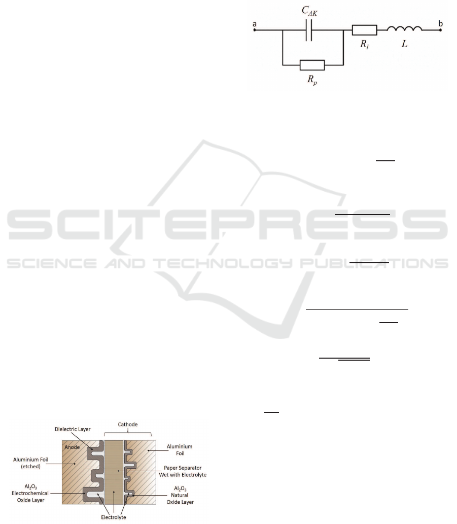
Figure 1: St r ucture of an electrolytic capacitor element.
The electrolytic capacitor elemen t depicted in Fi-
gure 1 may be modelled as the equivalent electric ci-
rcuit shown in Figure 2. The ideal capacitan ce is de-
noted by C
AK
. The resistance R
p
represents the in su-
lation resistance. The resistance R
l
correspo nds to the
series resistance of foils, paper and terminals. The in-
ductance of win dings and connections is represented
by L.
Figure 2: Equivalent electric circuit of an electrolytic capa-
citor.
The impedance of the equivalent circuit, shown in
Figure 2, takes the following form
Z
ab
= R
ESR
+ j
ωL
ESL
−
1
ωC
E
[Ω] (1)
where the equivalent series inductance (ESL) is given
by L
ESL
= L [H], the ESR is given by
R
ESR
= R
l
+
R
p
1 + ω
2
R
2
p
C
2
AK
[Ω] (2)
and the equivalent capacitance is given by
C
E
= C
AK
1 +
1
ω
2
R
2
p
C
2
AK
!
[F] (3)
Furthermore, the magnitude of the imped a nce and the
resonant frequ e ncy are given b y
|Z
ab
| =
r
R
2
ESR
+
ωL
ESL
−
1
ωC
E
2
[Ω] (4)
and
f
r
=
1
2π
√
L
ESL
C
E
[Hz] (5)
The impedance characteristics of an electrolytic ca-
pacitor is shown in Figure 3. For frequen cies f < f
r
impedance is dominated by the ca pacitive r eactance
X
C
=
1
ωC
E
, whereas for f > f
r
the impedance is domi-
nated by th e indu ctive reactance X
L
= ωL
ESL
. Moreo-
ver for f
1
< f < f
2
the impedanc e is mainly resistive
and hence dominated by R
ESR
.
Without lo ss of generality, it is assumed that the
power electronics system, on which the condition mo-
nitoring approach proposed in this paper will be app-
lied, is a DC-DC Buck converter. Consequently, since
DC-DC power converters typically operate at a lo-
wer frequency band compared with the resonant fre-
quency de fined in (5) and the equivalent series induc-
tance L
ESL
is relatively small, e. g. in the order of nH,
Condition Monitoring of Electrolytic Capacitors via ESR Estimation with Recursive Least Squares and Sliding Mode Techniques
475
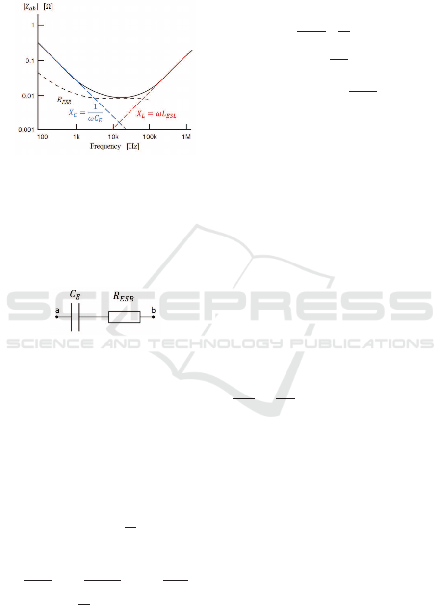
Figure 3: Frequency characteristics of |Z
ab
|.
ESL may be neglected. Nevertheless, the switching
frequency of the power co nverter is high enough, i.e.
typically in th e middle frequency range, for the im-
pedance Z
ab
to be dominated by R
ESR
. Note that the
switching frequency that will be considered in Section
(4) is 10 kHz which means that the impedance Z
ab
is
dominated by R
ESR
(see Figure 3). Sin c e this will be
the case considered in this paper, the equivalent cir-
cuit shown in Figure 2 c a n be simplified as shown in
Figure 4.
Figure 4: Simplified equivalent circuit of an electrolytic ca-
pacitor.
A widely app lied criterion states that the EoL of
electrolytic capacitors is reached when its capacitance
changes by 20% and/o r its ESR doubles (Hewitt et al.,
2016) (Soliman et al., 20 16). Other criteria are also
available. For instance, the military standard MIL-C-
62F has been used in (Celaya et al., 2 011) to define
that the EoF of an electrolytic capacitor is reached if
its ESR increases by 28 0-300% or the capacitance de-
creases by 20% with respect to the respective pristine
condition vales.
From the simplified equivalent circuit shown in
Figure 4, it follows that the difference of potential be-
tween anode and cathode te rminals is given by
v
ab
(t) = R
ESR
(t)i
C
(t) +
1
C
E
Z
t
0
i
C
(τ)dτ (6)
which, in turn, yields the following differential equa-
tion
dv
ab
(t)
dt
=i
C
(t)
dR
ESR
(t)
dt
+ R
ESR
(t)
di
C
(t)
dt
+
1
C
E
i
C
(t) −i
C
(0)
(7)
By defining
y
m
(t) =
dv
ab
(t)
dt
−
1
C
E
i
C
(t) −i
C
(0)
(8)
ϕ
T
(t) =
h
di
C
(t)
dt
i
C
(t)
i
(9)
and
ϑ =
h
R
ESR
(t)
dR
ESR
(t)
dt
i
T
(10)
the differential equation given in (7) can be written as
a generic linear mode l (Ljung, 1999) (Me ndel, 2008),
which is linear in the unknown vector of parameters
ϑ, and takes the following form
y
m
(t) = ϕ
T
(t)ϑ + η
m
(t) (11)
where η
m
(t) ∈ℜ denotes the measurement noise.
Since the inc rease of ESR is the best indicator of
capacitor degradation (Wang et al., 2012), the pro-
blem to be addressed in this paper is the on-line es-
timation of the equivalent series resistance R
ESR
(t)
for condition monitoring of electrolytic capacitors
through the gene ric linear m odel given in (11). This
problem will be tackled within the context of a DC-
DC c onverter as in (Buiatti et al., 2007a) (Soliman
et al., 201 6).
3 PROPOSED SOLUTION
The measurement y
m
(t) and the observation vector
ϕ(t) of the generic linear model (11) involve the
potential difference of the anode-ca thode termina ls
v
ab
(t) and the capacitor current i
C
(t), which are me-
asurable analogue signals, and their first der ivatives
dv
ab
(t)
dt
and
di
C
(t)
dt
respectively. In this paper, these de-
rivatives will be obtaine d by using sliding mode dif-
ferentiators (Levant, 1998). The voltage v
ab
(t) and
current i
C
(t) may be affected by noise and henc e the
classical differentiator based on linear approx imati-
ons will not produce satisfactory derivatives as will
be demonstrated in Section 4.
Although this paper is not conc erned with the phy-
sical imp le mentation of the proposed solution, two
conceptual designs are discussed in the sequel. The
scalar and vecto r signals y
m
(t) and ϕ(t) are obtained
using (8) and (9), which may be realised using opera-
tional amplifiers, and then these signals are sampled
at a frequency f
s
(in the order of tens or hundre ds of
kHz) prior to be processed by an RLS-based e stima -
tor implemented on a microcontroller, DSP or FPGA.
A b lock diagram of the condition m onitoring scheme
proposed in this paper is shown in Figure 5.
The proposed solution may also be im plemented
entirely on a digital programmable device. In this
ICINCO 2018 - 15th International Conference on Informatics in Control, Automation and Robotics
476
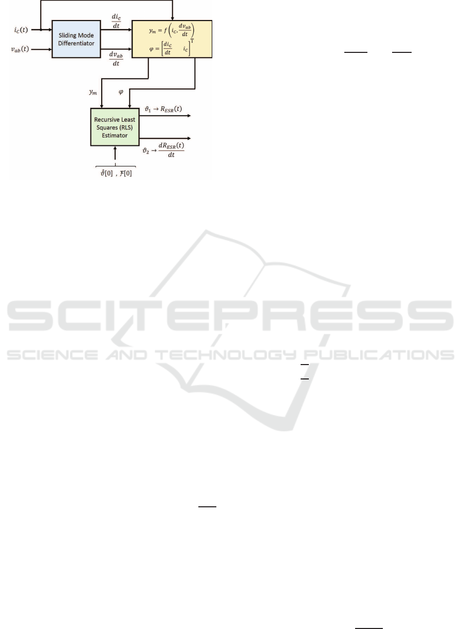
Figure 5: Block diagram of the proposed ESR estimation
scheme for electrolytic capacitor condition monitoring.
case, the electrolytic capacitor voltage v
ab
(t) and cur-
rent i
C
(t) would be sampled and a digital version
of the sliding m ode differentiators could be adopted.
Then, the representation of the signals y
m
[k] an d ϕ[k]
may be realised by software an d, of course, the RLS
algorithm is also implemented on software.
In what follows, the theory associated w ith the ro-
bust exact differentiator and the RLS estimation algo-
rithm is summarised.
3.1 Sliding Mode Differentiator
The sliding mode robust exact differentiator (Levant,
1998) corresponds to a second-order sliding mode (2-
sliding mode) technique. In order to introduce the
sliding mode differentiator used in the ESR estima-
tion scheme, some defin itions and main theor etical re-
sults a re provided for the sake of mathematical rigour
and completeness. Consider the space of measura-
ble fun ctions (or signals) bounded on an interval [a,b]
denoted b y M
[a,b]
and to which the continuous-time
input signal s
i
(t) belongs to. It is also assumed that
ks
i
(t)k = sup|s
i
(t)|.
A first-order differentiator D is said to be an ex-
act differentiator if its output signal, i.e. ˙s
i
(t) =
ds
i
(t)
dt
,
matches the time derivative of the input signal f (t).
Note that the orde r of the differentiator is the order
of the derivative produced. T he robustness of the dif-
ferentiator is an important feature sin ce in real-world
applications the input signal may be corr upted with
relatively small high -freque ncy noise, whic h a lways
exists and may have a large derivative. In this regard,
if the output signal of a differentiator D tends uni-
formly to D s
i
(t) as the input sig nal tends unifor mly
to s
i
(t), then the differentiator D is said to be a ro-
bust differentiator. More over, if a differentiator D has
both the exactness and robustness properties defined
previously, then it is said to be a correct differentiator.
For a practical real-time differentiator, as the ones
required by the electrolytic capacitor condition mo -
nitoring for generating
dv
ab
(t)
dt
and
di
C
(t)
dt
, it is assu-
med that the input signa l s
i
(t) is a me asurable locally
bounded functio n defined on the inte rval [0,∞) and
consists o f a base signal involving a de rivative with a
Lipschitz constant L > 0 and noise (Levant, 1998).
Define the auxiliary differential equation
˙x(t) = y(t) (12)
and the following first-order real-time robust exact
differentiator, whic h guarantees that x(t) → s
i
(t), i.e.
x(t) −s
i
(t) = 0 (Levant, 1993) (Levant, 1998):
y(t) = z(t) −λ|x(t) −s
i
(t)|
1/2
sgn(x(t) −s
i
(t)) (13)
˙z(t) = −κsgn(x(t) −s
i
(t)) (14)
where the signal y(t) is the output of the differentiator,
and scalars λ, κ ∈ℜ
+
are selected by the designer for
the convergence of y(t) to ˙s
i
(t). Sufficient conditions
will be provided below.
The solution of equations (12)-(14) has to be in-
terpreted in the sense of Filip pov’s theory (Filippov,
1988). Following the description presented in (Le-
vant, 1998), define
Φ(κ,λ, L ) = |Ψ(t
∗
)| (15)
where
Σ(t),Ψ(t)
is the solution of the system
˙
Σ = −|Σ|
1/2
+ Ψ (16)
˙
Ψ =
(
−
1
λ
2
(κ−L ) −|Σ|
1/2
+ Ψ > 0
−
1
λ
2
(κ+ L ) −|Σ|
1/2
+ Ψ ≤0
(17)
Σ(0) = 0 (18)
Ψ(0) = 1 (19)
where κ > L , λ 6= 0 and t
∗
= inf{t| t > 0, Σ(t) =
0, Ψ(t) < 0} with t
∗
< ∞. Note tha t the function
Φ(κ,λ, L ) has to be d etermined throu gh computer si-
mulations. The convergence criter ion of y(t) to
˙
f (t)
is stated in the following theorem.
Theorem 3.1 (Levant, 1998): Let κ > L > 0, λ > 0
and Φ(κ,λ,L ) < 1. Then, provided f (t) has a deri-
vative with Lipschitz constant L ( f ∈W (L ,2) where
W (L ,2) is the set of all input signals such tha t their
first derivatives have a Lip schitz constant L > 0), the
equality y(t) =
˙
f (t) holds identically after a finite-
time transient p rocess.
In (Levant, 19 98), the f ollowing sufficient conditions
for the convergence of y(t) to
˙
f (t) are given
κ > L , (20)
λ
2
≥ 4L
κ+ L
κ−L
. (21)
Condition Monitoring of Electrolytic Capacitors via ESR Estimation with Recursive Least Squares and Sliding Mode Techniques
477

Now consider the following assumptions: κ > L >
0, λ > 0, and Φ < 1.
Theorem 3.2 (Levant, 1998): Let s
i
(t) = s
i
0
(t)+η(t)
be the input signal, where s
i
0
(t) is a differentiable
base signal, s
i
0
(t) h as a derivative with Lipschitz con-
stant L > 0, and η(t) is the noise satisfying |η(t)| ≤
ε. Then, there exists a constant b > 0 depend e nt on
(κ − L )/λ
2
and (κ + L )/λ
2
such that after finite
time the inequality
|y(t) − ˙s
i
0
(t)| < λbε
1/2
(22)
is satisfied.
If κ and λ are chosen such that κ = ζ
1
L and λ =
ζ
2
L
1/2
respectively, then th e in equality
|y(t) − ˙s
i
0
(t)| <
˜
bL
1/2
ε
1/2
(23)
holds for some
˜
b(ζ
1
,ζ
2
) > 0.
A discrete-time version of the sliding mode d if-
ferentiator can be obtained by applying the one-step
Euler method to (12)-(14) (Livne and Levant, 2014):
x[k + 1] = x[k] + T
s
z[k] −λ
d
T
s
|e[k]|
1/2
sgn(e[k]) (24)
z[k + 1] = z[k] −κ
d
T
s
sgn(e[k]) (25)
where
e[k] = x[k] −s
i
[k] (26)
and T
s
is the sample time. The positive scalars λ
d
and κ
d
are the design p a rameters of th e sliding mode
differentiator.
3.2 Recursive Least Squares Estimator
Since the p arameter of interest for electrolytic capaci-
tor condition monitorin g is R
ESR
(t), which is a slo-
wly time-varying para meter, RLS with exponential
forgetting is integrated into the condition mon itoring
scheme proposed in this pap e r. The calculations in-
volved in this RLS method are given in the following
theorem.
Theorem 3.3 (Recursive Least Square s with Expo-
nential Forgetting): Given the estimation linear mo-
del
ˆy
m
[k] = ϕ
T
[k]
ˆ
ϑ[k] + η
m
[k] (27)
where ˆy
m
∈ ℜ is the model output, ϕ ∈ ℜ
r
is the re-
gressor vector which is a kn own deterministic vector
(the components of ϕ are said to b e the regression va-
riables), and
ˆ
ϑ ∈ℜ
r
is the parameter vector estimate.
Provided that
ˆ
ϑ[0] =
ˆ
ϑ
0
and P[0] = P
0
, the least
squares estimate of the vector of unkn own parameters
ˆ
ϑ satisfies the following recursive equations:
ˆ
ϑ[k] =
ˆ
ϑ[k −1]+K [k]
y
m
[k] −ϕ
T
[k]
ˆ
ϑ[k −1]
(28)
where
K [k] = P [k]ϕ[k] (29)
= P[k −1]ϕ[k]
λ
RLS
+ ϕ
T
[k]P [k −1]ϕ[k]
−1
(30)
and
P[k] =
1
λ
RLS
I −K [k]ϕ
T
[k]
P[k −1] (31)
and minimises the cost function
J(
ˆ
ϑ,τ) =
1
2
τ
∑
k=1
λ
τ−k
RLS
y
m
[k] −ϕ
T
[k]
ˆ
ϑ[k]
2
(32)
where the forgetting factor λ
RLS
is such that 0 <
λ
RLS
< 1.
The initial value P (0) is chosen as
P(0) = γ
RLS
I (33)
where γ
RLS
∈ ℜ is a large number.
The gain vector K [k] in Theorem (3.3 ) provides
a p roportional correction to the difference between
the ac tual measurement y
m
[k] and the estimate out-
put ˆy
m
[k] based on the previous parameter estimate
ˆ
ϑ[k − 1]. Moreover, cost function (32) involves a
time-varying weighting of the squared of this diffe-
rence, i.e . e
2
y
= (y
m
[k] −ϕ
T
[k]
ˆ
ϑ[k −1])
2
, through the
factor λ
τ−k
RLS
. Thus, it is possible to give more empha-
sis to recently observed measurements ra ther than to
older data.
Note that λ
RLS
= 1 corresponds to the fundamental
RLS a lgorithm in which all data are weighted equally
and the algorithm has an infinite memory length (Zhu-
ang, 1998). The ch oice of λ
RLS
is a trade-off between
tracking and noise sensitivity ( Ljung, 1999). That is,
less we ight to older me a surements, i.e. λ
RLS
small,
means that older data is forgo tten faster. However,
the algorithm is more sensitive to noise. Usually,
the forgetting factor λ
RLS
is c hosen from the interval
[0.95 , 0.99]. In (Isermann and M¨unchhof, 2011), it
is suggested that λ
RLS
has to be selected as follows:
(i) a small λ
RLS
if the rate of c hange of the parameter
is large and only small noise is allowed; (ii) a large
λ
RLS
if th e rate of change of the parameter is small
and noise can be larger.
4 DESIGN AND SIMULATION
In this section, a DC-DC buck converter (see Figure
6) with nominal parameter values given in Tab le 1 is
considered. For this pu rpose, a model of th e entire sy-
stem (i.e. DC-DC converter and condition monitor ing
scheme) was implemented on MATLAB/ Simulink.
ICINCO 2018 - 15th International Conference on Informatics in Control, Automation and Robotics
478
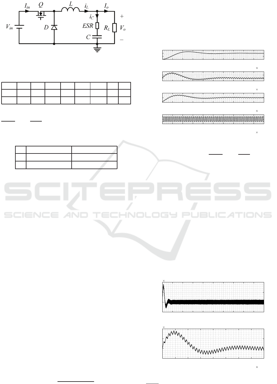
Figure 6: DC-DC buck converter schematic.
Table 1: Nominal parameter values for the DC-DC Buck
Converter.
V
in
L r
L
C ESR R
L
f
sw
DS V
0
[V] [H] [µΩ] [mF] mΩ Ω [kHz] [%] [V]
200 0.21 68.7 1.041 2 5 1.584 10 50 100
Sliding mode differentiators for estimation of
dv
ab
(t)
dt
and
di
C
(t)
dt
were designed and their gains are
shown in Table 2.
Table 2: Sliding mode differentiator gains.
Differentiator 1 Differentiator 2
λ 420 ×10
3
8.40 ×10
12
κ 4.7250 ×10
12
2.2 ×10
6
The RLS with forgetting factor algorithm, presen-
ted in Theorem 3 .3, was implemented as a MATLAB
function. The following parameter values w e re used
on the computer simulations: λ
RLS
= 0.99, ϑ(0) =
[0 0]
T
and F (0) = 100I. A large constant forget-
ting factor has been selected sinc e ESR is a slowly
time-varying parameter. Furthermore, this large λ
RLS
allows for a reduced estimation no ise. The sample
time considered for the RLS estimator was 100 kHz,
i.e. 10 f
sw
. Regarding, the MATLAB/Simulink model
configuration parameters, they were set a s follows:
ode1 (Euler) solver with fixed-step size (fu ndamental
sample time) of 1 ×10
−9
seconds.
An experime nt involving a simulated change in
the ESR value (see, for example, the black colour
curve in Figure 12) was carried out. Note that in or-
der to emulate the electroly tic capacitor d egra dation,
the E SR value was gradually increased. Moreover,
the capacitor voltage and curr e nt measurements were
corrupted by noise. In this respect, two different uni-
formly d istributed random signals were injected to the
capacitor voltage and current measurements, i.e. η
v
ab
:
amplitude = ±1 ×10
−3
[V] and seed = 2, and η
i
C
:
amplitude = ± 5 ×10
−3
[A] and seed = 4 . The sample
time of 1 ×10
−6
seconds was used for both signals.
The results obta ined with the pr oposed scheme are
compare d against the following c la ssical first-order li-
near appr oximation differentiator (LAD):
G(s) =
s
100 ×10
9
s + 1
(34)
This differentiator was used alongside the very same
RLS with forgetting algorithm used for the sliding
mode based scheme. In this paper, this approach will
be called the classical scheme or method.
A detail of the perf ormance of the DC-DC buck
converter is shown in Figure 7.
0 0.5 1 1.5 2 2.5 3 3.5 4 4.5 5
10
-3
0
50
100
150
v
out
(t) [V]
0 0.5 1 1.5 2 2.5 3 3.5 4 4.5 5
10
-3
0
5
10
i
C
(t) [A]
0 0.5 1 1.5 2 2.5 3 3.5 4 4.5 5
10
-3
0
10
20
i
L
(t) [A]
0 0.5 1 1.5 2 2.5 3 3.5 4 4.5 5
time [s]
10
-3
-0.5
0
0.5
1
1.5
SW
Figure 7: DC-DC buck converter dynamic response (zoom).
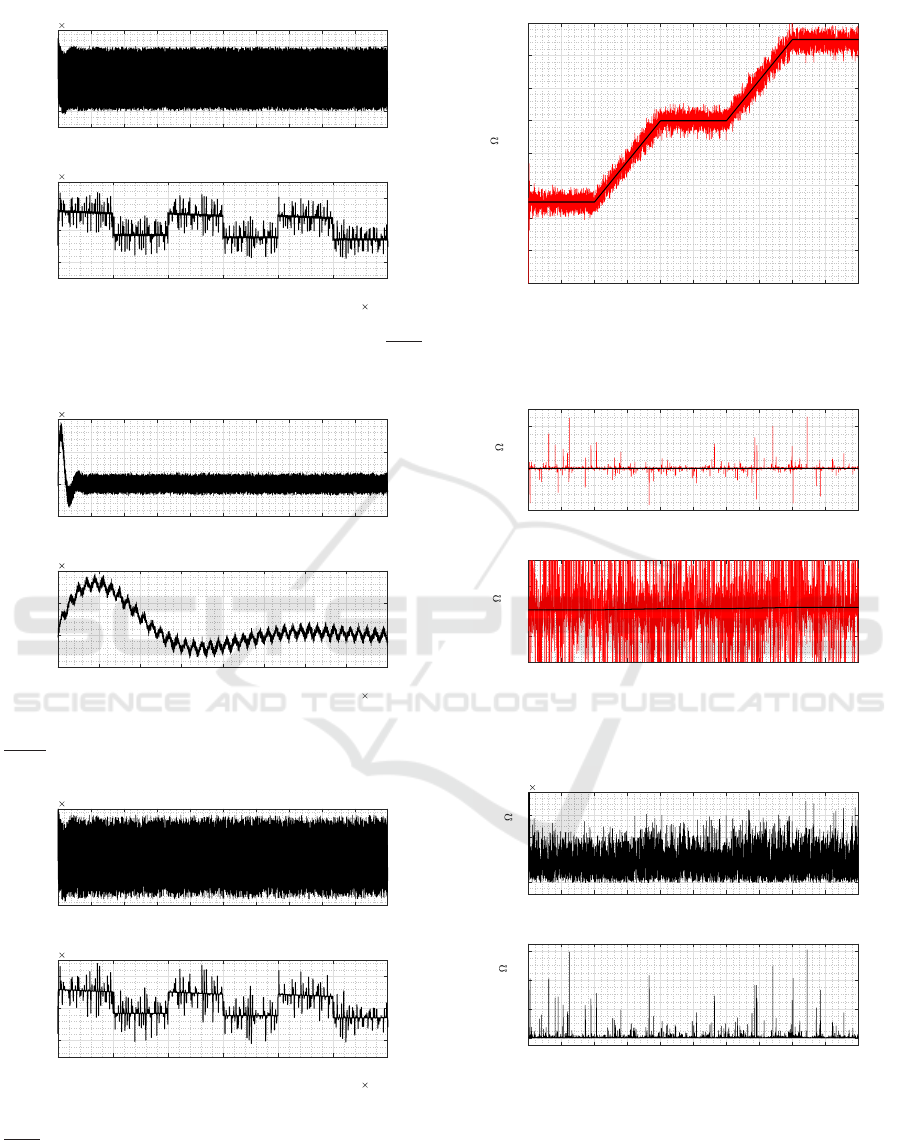
The first derivatives
dv
ab
(t)
dt
and
di
C
(t)
dt
, obtained
with the sliding m ode differentiato rs, are shown in Fi-
gures 8 and 9 respectively. On the other hand, the
same derivatives but produced by the classic LAD
are depicted in Figures 10 and 11. The better per-
formance of the sliding mode differentiator is evident
from these graphs. This will become even more evi-
dent wh e n assessing the performance of b oth condi-
tion monitoring schemes later on.
The time evolution of the true and estimated ESR,
using the proposed scheme and the classical met-
hod, are shown in Figure 12 and 13. Furthermore,
the corresponding errors e
ESR
SMS
= |R
ESR
−
ˆ
R
ESR
SMS
|
and e
ESR
CM
= |R
ESR
−
ˆ
R
ESR
CM
| are provided in Figure
14. The per formance of the classical method (CM)
is indeed unaccep ta ble because it cannot estimate the
ESR in the case of noisy measurements and hence
0 0.005 0.01 0.015 0.02 0.025 0.03 0.035 0.04 0.045 0.05
time [s]
-1
0
1
2
d v
ab
/dt [V/s]
10
5
First derivative of v
ab
(t)
0 0.5 1 1.5 2 2.5 3 3.5 4
time [s]
10
-3
-1
0
1
2
d v
ab
/dt [V/s]
10
5
First derivative of v
ab
(t) (zoom)
Figure 8: First derivative of the capacitor voltage, i.e.
dv
ab
(t)
dt
, obtained with the sliding mode differentiator.
Condition Monitoring of Electrolytic Capacitors via ESR Estimation with Recursive Least Squares and Sliding Mode Techniques
479
0 0.005 0.01 0.015 0.02 0.025 0.03 0.035 0.04 0.045 0.05
time [s]
-1
0
1
d i
C
/dt [A/s]
10
5
First derivative of i
C
(t)
1 1.5 2 2.5 3 3.5 4
time [s]
10
-4
-1
0
1
d i
C
/dt [A/s]
10
5
First derivative of i
C
(t) (zoom)
Figure 9: First derivative of the capacitor current, i.e.
di
C
(t)
dt
,
obtained with the sliding mode differentiator.
0 0.005 0.01 0.015 0.02 0.025 0.03 0.035 0.04 0.045 0.05
time [s]
-1
0
1
2
d v
ab
/dt [V/s]
10
5
First derivative of v
ab
(t)
0 0.5 1 1.5 2 2.5 3 3.5 4
time [s]
10
-3
-1
0
1
2
d v
ab
/dt [V/s]
10
5
First derivative of v
ab
(t) (zoom)
Figure 10: First derivative of the capacitor voltage, i.e.
dv
ab
(t)
dt
, obtained with the classical first order LAD.
0 0.005 0.01 0.015 0.02 0.025 0.03 0.035 0.04 0.045 0.05
time [s]
-1
0
1
d i
C
/dt [A/s]
10
5
First derivative of i
C
(t)
1 1.5 2 2.5 3 3.5 4
time [s]
10
-4
-1
0
1
d i
C
/dt [A/s]
10
5
First derivative of i
C
(t) (zoom)
Figure 11: First derivative of the capacitor current, i.e.
di
C
(t)
dt
, obtained with the classical first order LAD.
has a much bigger estimation error than the propo-
sed scheme. The sliding mode-ba sed scheme (SMS)
outperforms the classical approach.
0 0.005 0.01 0.015 0.02 0.025 0.03 0.035 0.04 0.045 0.05
time [s]
0
0.01
0.02
0.03
0.04
0.05
0.06
0.07
0.08
ESR [ ]
Equivalent Series Resistance (ESR)
Figure 12: True and estimated ESR obtained with the pro-
posed scheme.
0 0.005 0.01 0.015 0.02 0.025 0.03 0.035 0.04 0.045 0.05
time [s]
-50
0
50
ESR [ ]
Equivalent Series Resistance (ESR)
0 0.005 0.01 0.015 0.02 0.025 0.03 0.035 0.04 0.045 0.05
time [s]
-1
-0.5
0
0.5
1
ESR [ ]
Equivalent Series Resistance (ESR)
Figure 13: True and estimated ESR obtained with the clas-
sic method.
0 0.005 0.01 0.015 0.02 0.025 0.03 0.035 0.04 0.045 0.05
time [s]
0
2
4
6
8
Abs(error) [ ]
10
-3
Estimation error (Proposed Scheme)
0 0.005 0.01 0.015 0.02 0.025 0.03 0.035 0.04 0.045 0.05
time [s]
0
20
40
60
Abs(error) [ ]
Estimation error (Classical Method)
Figure 14: Estimation errors.
5 CONCLUSIONS
The sliding mod e RLS based scheme for ele ctrolytic
capacitor con dition monitoring proposed in this pa-
ICINCO 2018 - 15th International Conference on Informatics in Control, Automation and Robotics
480

per is capable of estimating the equivalent series re-
sistance (ESR) on-line desp ite noisy me asurements.
A constant forgetting factor has been used in the RLS
algorithm since the ESR is a slowly time-varying pa-
rameter. Robust slidin g mode differentiation ha s been
satisfactorily applied for calculating signals required
by the RLS algorithm.
The new co ndition monitoring approach outp er-
forms an equivalent scheme based on linear approx-
imation differentiators and the RLS with forgetting
factor algorithm. The scheme is relatively simple in
its form and design. A detailed design example has
illustrated the simplicity of th e metho d. Moreover,
computer simulation results have demonstrated the ef-
fectiveness of the new capa citor condition monitoring
scheme in which th e degradation of an electrolytic ca-
pacitor on a DC-DC buck converter has been conside-
red as proof of co ncept.
REFERENCES
Abdennadher, K., Venet, P., Rojat, G., Retif , J. M., and Ros-
set, C. (2008). A real ti me predictive maintenance
system of aluminium electrolytic capacitors used in
uninterrupted power supplies. In 2008 IEEE Industry
Applications Society Annual Meeting, pages 1–6.
Abdennadher, K., Venet, P., Rojat, G., Retif , J. M., and Ros-
set, C. (2009). Kalman filter used for on-line monito-
ring and predictive maintenance system of aluminium
electrolytic capacitors in UPS. In IEEE Energy Con-
version Congress and Exposition, pages 3188–3193.
Alwitt, R. and H ills, R . (1965). The chemistry of failure of
aluminum electrolytic capacitors. IEEE Transactions
on Parts, Materials and Packaging, 1(2):28–34.
Amaral, A. M. R., Buatti, G., Ribeiro, H., and Cardoso, A.
(2007). Using DFT to obtain the equivalent circuit of
aluminum electrolytic capacitors. In 7th Int. Conf. on
Power Elect. and Drive Systems, pages 434–438.
Buiatti, G. M., Amaral, A. M. R., and Cardoso, A. J. C.
(2007a). ESR estimati on method for DC/DC conver-
ters through simplified regression models. In IEEE
Ind. Applications Annual Meeting, pages 2289–2294.
Buiatti, G. M., Amaral, A. M. R., and Cardoso, A. J. M.
(2007b). Parameter estimation of a DC/DC buck con-
verter using a continuous time model. In European
Conf. on Power Elect. and Applications, pages 1–8.
Celaya, J. R., Kulkarni, C., Biswas, G., Saha, S., and Goe-
bel, K. (2011). A model-based prognostics metho-
dology for electrolytic capacitors based on electrical
overstress accelerated aging. In Proc. of the Conf. of
the Prognostics and Health Management Soc.
Filippov, A. F. (1988). Differential Equations with Discon-
tinuous Righthand Sides. Kluwer Acad. Publishers.
Hewitt, D. A., Green, J. E., Davidson, J. N., Foster, M. P.,
and St one, D. A. (2016). Observation of electrolytic
capacitor ageing behaviour for the purpose of prog-
nostics. In Proc. of the 42nd Conf. of the IEEE Ind.
Elect. Society (IE CON 2016).
Imam, A. M., Habetler, T. G., Harley, R. G., and Divan,
D. (2005). Failure prediction of electrolytic capaci-
tor using DSP methods. In 20th IEEE Applied Power
Elect. Conf. and Exp., volume 2, pages 965–970.
Isermann, R. and M¨unchhof, M. (2011). Identification of
Dynamic Systems: An Introduction with Applications.
Springer-Verlag.
Kalman, R. E. (1960). A new approach to linear filtering
and prediction problems. Transactions on the ASME-
Journal of Basic Engineering, 82:35–45.
Kulkarni, C., Biswas, G., Koutsoukos, X., Celaya, J., and
Goebel, K. (2010). Experimental studies of ageing in
electrolytic capacitors. In Proc. of the Conf. of the
Prognostics and Health Management Soc., pages 1–7.
Kulkarni, C. S., Celaya, J. R., Biswas, G., and Goebel, K.
(2012). Accelerated aging experiments for capacitor
health monitoring and prognostics. In IEEE AUTO-
TESTCON Proceedings, pages 356–361.
Levant, A. (1993). Sliding order and sliding accuracy in
sliding mode control. Int. J. of Control, 58(6):1247–
1263.
Levant, A. (1998). Robust exact differentiation via sliding
mode technique. Automatica, 34(3):379–384.
Livne, M. and Levant, A. (2014). Proper discretiza-
tion of homogeneous differentiators. Automatica,
50(8):2007–2014.
Ljung, L. (1999). System Identification - Theory for the
User. Pr entice-Hall , 2nd edition.
Mendel, J. M. (2008). Lessons in Estimation Theory for Sig-
nal Processing, Communications, and Control. Pear-
son Technology Group, 2nd edition.
Nichicon Corporation ((n.d.) ) . Technical Notes on Alumi-
num Electrolytic Capacitors. Tech. Note 8101E.
Shtessel, Y., Edwards, C. , Fridman, L., and A., L. (2014).
Sliding Mode Control and Observation. Bir kh¨auser.
Soliman, H., Wang, H., and Blaabjerg, F. (2016). A re-
view of the condition monitoring of capacitors in po-
wer electronic converters. IEEE Tran. on Ind. Appli-
cations, 52(6):4976–4989.
Wang, G. , Guan, Y., Zhang, J., Wu, L ., Zheng, X., and Pan,
W. (2012). ESR estimation method for DC-DC con-
verters based on improved EMD algorithm. In Proc.
of the IE EE Prognostics and System Health Manage-
ment Conf., pages 1–6.
Wang, H. and Blaabjerg, F. (2014). Reliability of capa-
citors for DC-link applications in power electronic
converters: An overview. IEEE Trans. on Ind. App.,
50(5):3569–3578.
Zhuang, W. (1998). RLS algorithm with variable foget-
ting factor for decision feedback equalizer over time-
variant fading channels. Wireless Personal Communi-
cations, 8(1):15–29.
Condition Monitoring of Electrolytic Capacitors via ESR Estimation with Recursive Least Squares and Sliding Mode Techniques
481
