
Comparison of Constraint-handling Techniques Used in Artificial Bee
Colony Algorithm for Auto-Tuning of State Feedback Speed Controller
for PMSM
Rafal Szczepanski
1
,Tomasz Tarczewski
1
, Krystian Erwinski
1
and Lech M. Grzesiak
2
1
Department of Automatics and Measurement Systems, Nicolaus Copernicus University,
Grudziadzka 5, 87-100 Torun, Poland
2
Institute of Control and Industrial Electronics, Warsaw University of Technology, Koszykowa 75, 00-662 Warsaw, Poland
Keywords:
Constraint-handling Technique, Augmented Lagrangian, Deb’s Rules, Optimization, Artificial Bee Colony,
State Feedback Speed Controller, PMSM.
Abstract:
This article focuses on comparison of two constraint-handling techniques: Deb’s Rules (DR) and Augmented
Lagrangian (AL) applied to Artificial Bee Colony (ABC) algorithm that is used for auto-tuning of state feed-
back speed controller (SFC) for permanent magnet synchronous motor (PMSM). The task of the optimization
algorithm is to determine the elements of Q and R weighting matrices in linear quadratic regulator (LQR) op-
timization process. Chosen matrices guarantee the best performance according to given optimization criteria.
Safety and proper operation of the motor requires the use of constraint-handling (C-H) technique. The ABC in
its original version cannot handle the constrained optimization problems, therefore necessary modifications of
considered optimization algorithm are depicted. Simulation and experimental results showed that AL techni-
que allows to obtain a better convergence of ABC algorithm and a better performance of the PMSM drive than
DR technique.
1 INTRODUCTION
Optimization problems are present in all branches
of applied sciences and engineering sciences. Most
practical applications require limiting of physical va-
riables, which involve equality or inequality con-
straints. Over the past years, nature-inspired opti-
mization algorithms, such as Artificial Bee Colony
(ABC), Particle Swarm Optimization (PSO), Gene-
tic Algorithm (GA), Flower Pollination Algorithm
(FPA), Ant-Colony (AC), Grey Wolf Optimizer Al-
gorithm (GWO) and many others, have gained popu-
larity in solving engineering optimization problems
(Kaminski and Najdek, 2018), (Wang et al., 2016),
(Senberber and Bagis, 2017). Most of nature-inspired
algorithms, in their original versions, can solve only
unconstrained optimization problems. Therefore re-
searchers had to apply C-H techniques (Gionfra et al.,
2017), (Deb, 2000), (Khalilpourazari and Khalilpou-
razary, 2018), (Long et al., 2017), (Tarczewski and
Grzesiak, 2018), (Szczepanski et al., 2017). There
are many techniques to handling constraints (Mezura-
Montes and Coello, 2011), but the most commonly
used groups are: penalty functions and, separation of
objective function and constraints. First group allows
transformation of constrained optimization problems
into unconstrained optimization problems by adding
penalty functions to the objective function for each
constraint. In order to favor selection of a feasible
(e.g. valid) solution, the penalty functions decrease
the fitness of an infeasible solution. The opposite
idea of C-H technique is based on separation of the
objective function and constraints. Keeping both va-
lues apart allows for optimization on an unconstrained
problem by calculating fitness of solution with dif-
ferent equations for feasible and infeasible solution
or tournament selection. Mathematically, the equa-
lity constrained optimization problem can be presen-
ted as:
Minimize
subject to:
f (x)
h(x) = 0
(1)
where f : R
n
→ R, h : R
n
→ R
m
and x
i
, i = 1, ...,n is
bounded by lower and upper limits l
i
≤ x
i
≤ u
i
which
define the search space.
The reliable comparison of C-H techniques re-
quires non-trivial constrained optimization problem.
In this paper, an auto-tuning process of state feed-
Szczepanski, R., Tarczewski, T., Erwinski, K. and Grzesiak, L.
Comparison of Constraint-handling Techniques Used in Artificial Bee Colony Algorithm for Auto-Tuning of State Feedback Speed Controller for PMSM.
DOI: 10.5220/0006904002690276
In Proceedings of the 15th International Conference on Informatics in Control, Automation and Robotics (ICINCO 2018) - Volume 1, pages 269-276
ISBN: 978-989-758-321-6
Copyright © 2018 by SCITEPRESS – Science and Technology Publications, Lda. All rights reserved
269

back speed controller for PMSM has been chosen.
PMSM has wide range of applications (e.g. electri-
cal and hybrid vehicles, CNC machines, ventilating
and air conditioning applications (Chan, 1993), (Liu
et al., 2016), (Dai et al., 2007), (Lin et al., 2006),
(Abrahamsen et al., 2000). Variable speed drives with
PMSMs are commonly controlled by cascade of PI
controllers or by state feedback controller. The latter
control structure is applied in the proposed approach
due to superior dynamical properties, with particular
emphasis on disturbance compensation (Tarczewski
and Grzesiak, 2016). Since all state-space variables
of the plant are simultaneously controlled by a sin-
gle controller, the design process requires selection
of all coefficients at the same time. This is a non-
trivial task, especially for complex control systems.
The trial-and-error method is commonly used to tune
SFC regardless of linear-quadratic or pole-placement
design technique. In (Franklin et al., 1998), Bry-
son’s method is described for initial guess of diago-
nal elements of penalty matrices. The pole-placement
technique is based on location of poles, which usu-
ally requires expert knowledge. A novel usage of
nature-inspired optimization algorithm to auto-tuning
SFC for PMSM was proposed in (Tarczewski and Gr-
zesiak, 2018), where DR technique has been applied
as C-H technique. To the best our knowledge, usage
of AL technique for the above described optimization
problem and comparison of C-H techniques for auto-
tuning of state-space controller were not presented be-
fore.
In this paper LQR is used to tune SFC gains. Ho-
wever the coefficients of penalty matrices are obtai-
ned by applying ABC algorithm. Two C-H techni-
ques are investigated to analyze the performance of
constrained, nature-inspired optimization algorithm.
2 STATE FEEDBACK SPEED
CONTROLLER FOR PMSM
The knowledge of state-space description of PMSM
fed by voltage-source inverter (VSI) is necessary for
synthesis process of state feedback speed controller
for PMSM. It was assumed that: (i) all state-space
variables of the motor are directly measured using ap-
propriate sensors and calculations and, (ii) a single
SFC controls all state-space variables.
2.1 Linearized Model of the PMSM
In order to design SFC for PMSM, state-space repre-
sentation of the plant (i.e. PMSM fed by VSI) should
be introduced. The following assumptions will be
adopted to design a linear description of the drive’s
model:
• a simple feedback linearization procedure will be
employed,
• VSI’s dynamic behavior and non-linearities will
be neglected,
• a PMSM with surface mounted magnets will be
considered, and therefore L
d
= L
q
= L
s
,
• load torque cannot be measured, and therefore it
will be omitted,
• reference signal’s internal model will be included.
The aforementioned assumptions lead to the follo-
wing representation of the considered plant in d-q re-
ference frame (Tarczewski and Grzesiak, 2018):
dx
i
(t)
dt
= A
i
x
i
(t) +B
i
u
i
(t) + F
i
r
i
(t) (2)
with:
A
i
=
−
R
s
L
s
0 0 0
0 −
R
s
L
s
0 0
0 −
K
t
J
m
−
B
m
J
m
0
0 0 1 0
, F
i
=
0
0
0
−1
,
B
i
=
K
p
L
s
0
0
K
p
L
s
0 0
0 0
, x
i
(t) =
i
d
(t)
i
q
(t)
ω
m
(t)
x
ω
(t)
,
u
i
(t) =
u
ld
(t)
u
lq
(t)
, r
i
(t) = ω
m re f
(t),
where: R
s
, L
s
– resistance and inductance of the
PMSM stator, J
m
– moment of inertia, K
t
– torque
constant, B
m
– viscous friction, i
d
(t), i
q
(t) – current
space vector components, ω
m
(t) – angular speed of
the PMSM shaft, K
p
– gain of VSI, u
ld
(t), u
lq
(t)
– linear components of control voltages, ω
m re f
(t)
– reference value of angular speed. The last state-
space variable has been introduced to ensure steady-
state error-free operation for step changes of reference
speed and load torque. It is specified by the following
formula:
x
ω
(t) =
t
Z
0
[ω
m
(τ) − ω
mre f
(τ)]dτ (3)
ICINCO 2018 - 15th International Conference on Informatics in Control, Automation and Robotics
270

Shown in (2), linear components of control voltages
are obtained by using feedback linearization proce-
dure described in (Grzesiak and Tarczewski, 2012):
u
ld
(t) = u
sd
(t) + u
md
(t) (4)
u
lq
(t) = u
sq
(t) − u
mq
(t) (5)
with:
u
md
(t) = pω
m
(t)L
s
i
q
(t)/K
p
(6)
u
mq
(t) = pω
m
(t)(L
s
i
d
(t) + ψ
f
)/K
p
(7)
where: u
sd
(t), u
sq
(t) – space vector components of
inverter control voltages, u
md
(t), u
mq
(t) – non-linear
components of control voltages, p – the number of
pole pairs, ψ
f
– permanent magnet flux linkage.
2.2 State Feedback Controller
A discrete state feedback speed controller obtained
for (2) has the following form:
u
i
(n) = −Kx
i
(n) = −K
x
x(n) − K
ω
x
ω
(n) (8)
with:
K = [K
x
K
ω
] =
k
x1
k
x2
k
x3
k
ω1
k
x4
k
x5
k
x6
k
ω2
(9)
where: n – a discrete sample time index, k
x1
, k
x2
,
k
x3
, k
x4
, k
x5
, k
x6
, k
ω1
and k
ω2
– gain coefficients
of SFC. Proper selection of gain coefficients is not
trivial, because all of them should be simultane-
ously chosen. These could be determined by using
linear-quadratic optimization (Grzesiak and Tarczew-
ski, 2011) or pole placement technique (Grzesiak and
Tarczewski, 2012). In the proposed approach the first
one is used. The method minimizes discrete perfor-
mance index for weighting matrices Q and R:
I
LQR
=
∞
∑
n=0
x
T
i
(n)Qx
i
(n) + u
T
li
(n)Ru
li
(n)
(10)
with
Q = diag(
q
1
q
2
q
3
q
4
),
R = diag(
r
1
r
2
)
(11)
where: q
1
, q
2
, q
3
, q
4
, r
1
and r
2
are coefficients of pen-
alty matrices. The trial-and-error manual approach to
determine those values could be time-consuming and
challenging process for the control system conside-
red. In this paper the Artificial Bee Colony algorithm
will be employed to obtain Q and R values.
3 CONSTRAINED ARTIFICIAL
BEE COLONY ALGORITHM
An Artificial Bee Colony optimization algorithm has
been proposed by Karaboga in 2005. It is based on
the intelligent foraging behavior of honey bee swarm
(Karaboga and Basturk, 2007). In the next years Ka-
raboga proved experimentally that ABC has better
performance than other popular nature-inspired algo-
rithms (Karaboga and Basturk, 2008).
3.1 Artificial Bee Colony Algorithm
The block diagram of the ABC algorithm is shown in
Fig. 1. The algorithm divides the colony into three
groups: employed bees, onlooker bees and scouts.
Employed bees look for a new food source in the
randomly chosen neighbourhood.
Onlooker bees go from their actual food source to
another food source depending on the nectar amount
in the source. The last group, scouts, only appear
when a food source is abandoned and a new one has
to be found. An employed bee becomes a scout when
the number of failed attempts exceeds the predefined
parameter called limit. After initialization, the algo-
rithm repeats all aforementioned phases MCN times.
To reduce the diversity of new food sources produ-
ced by employed and onlooker bees, the modifica-
tion rate MR is introduced. The parameter determi-
nes probability of change in dimension. Well mat-
ched MR allows to reduce diversity without conver-
gence reduction. Values of ABC used in the conside-
red auto-tuning problem are listed in Table 1.
Table 1: Artificial Bee Colony parameters.
Parameter & (Symbol) Value
No of optimized parameters (D) 6
No of colony size (NP) 10
No of food sources (FN) NP/2
Maximum no of cycles (MCN) 50
Control parameter (limit) FN × D
Scout production period (SPP) FN × D
Modification rate (MR) 0.8
Lower bounds (lb
1
÷ lb
D
) 1 × 10
−3
Upper bounds (ub
1
÷ ub
D
) 1 × 10
4
Weighting coefficient (α) 1 × 10
−3
In order to apply the ABC for automatic selection
of Q and R values that assure satisfactory behavior of
the drive, an optimization performance index should
be defined. On the basis of information contained in
(Tarczewski and Grzesiak, 2018), the following for-
mula was chosen:
f (x) =
N
∑
n=0
e
2
ω
(x,n)nT
s
+ e
2
id
(x,n)nT
s
+ α∆u
2
sq
(x,n)
(12)
with:
e
ω
(x,n) = ω
m
(x,n) − ω
mre f
(x,n)
Comparison of Constraint-handling Techniques Used in Artificial Bee Colony Algorithm for Auto-Tuning of State Feedback Speed
Controller for PMSM
271
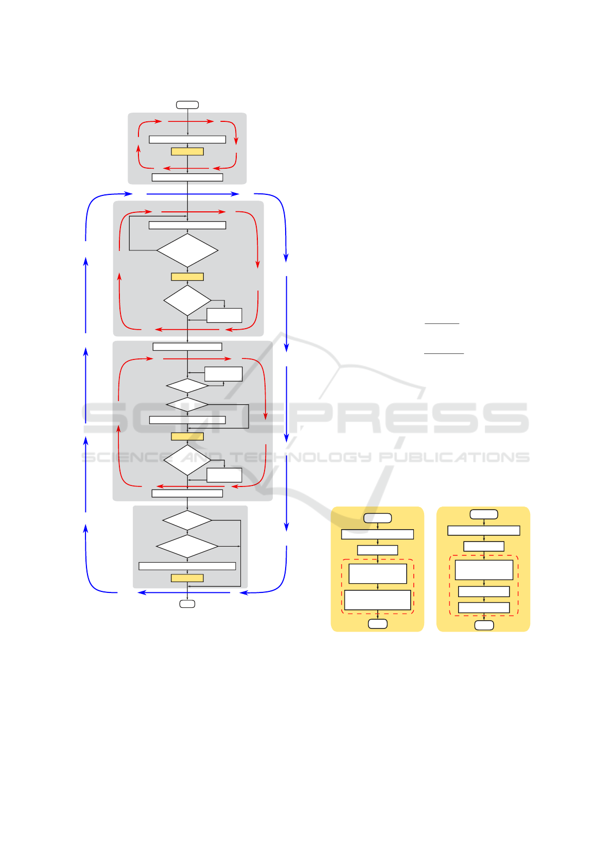
START
Y
N
Y
N
the probability calculation
remember the best solution
evaluation
evaluation
random generation of Q & R
p
i
> rn?
Y
N
MR> rn?
generation of a new Q & R
Y
N
Y
N
evaluation
END
generation of a new Q & R
remember the best solution
INITIALIZATION
EMPLOYED BEES PHASE
ONLOOKER BEES PHASE
SCOUTS PHASE
for each food source
is at least one
parameter changed?
is solution
improved?
increment
trial counter
for each food source
for each food source
check for the
next solution
is solution
improved?
increment
trial counter
repeat MCN times
Y
N
Y
N
random generation of a new Q & R
evaluation
trial counter≥limit?
is SPP
reached?
Figure 1: The block diagram of Artificial Bee Colony algo-
rithm.
e
id
(x,n) = i
d
(x,n) − i
dre f
(x,n)
∆u
sq
(x,n) = [u
sq
(x,n) − u
sq
(x,n − 1)]/T
s
where: α – manually selected coefficient, i
dre f
(x,n) –
the reference value of d-axis current. From (12) it can
be seen, that the performance index has three com-
ponents: the first one is responsible for steady-state
error-free operation and dynamical properties of the
drive’s angular velocity, the second one should assure
zero d-axis current control strategy, and the last one
is responsible for minimization of chattering in q-axis
control signal.
It should be noted, that despite of performance in-
dex selection, an original version of ABC (i.e. non-
constrained) cannot be directly employed for auto-
tuning of SFC. Since safe operation of the drive re-
quires limitation of q-axis current and q-axis control
signal, a constraint-handling technique should be app-
lied. The constraints are computed from the following
formulas:
h
i
q
(x) =
N
∑
n=0
MAX(0,c
i
q
(x,n))
h
u
sq
(x) =
N
∑
n=0
MAX(0,c
u
sq
(x,n))
(13)
with:
c
i
q
(x,n) =
|i
q
(x,n)|
i
q max
− 1
c
u
sq
(x,n) =
|u
sq
(x,n)|
u
sq max
− 1
Although C-H method based on Deb’s Rules has
been recently employed to auto-tuning of SFC (Tar-
czewski and Grzesiak, 2018), it is worth to examine
the impact of other techniques on the convergence
of ABC algorithm as well as on the performance of
the PMSM drive. For that reason, Powell-Hestenes-
Rockafellar Augmented Lagrangian (Powell, 1967),
(Hestenes, 1969), (Rockafellar, 1974) will be com-
pared with Deb’s Rules (Deb, 2000) C-H technique.
Due to this, two variants of the evaluation block will
be used. Their contents are shown in Fig. 2.
controller calculation
START
END
simulation
f(x) and violation
calculation
tournament selection
(Deb's rules)
controller calculation
START
END
simulation
f(x) and h(x)
calculation
L(x) calculation
minimize L(x)
EvALUATION
EvALUATION
a) b)
Augmented Lagrangian technique
Deb's rules technique
Figure 2: Content of evaluation block.
3.2 Deb’s Rules Technique
In 2000 Deb proposed a C-H technique based on se-
paration of objective function and constraints. No-
wadays this method is known as Deb’s Rules (DR)
and it is used with many nature-inspired optimization
algorithms (e.g. PSO (Gionfra et al., 2017), ABC
ICINCO 2018 - 15th International Conference on Informatics in Control, Automation and Robotics
272

(Tarczewski and Grzesiak, 2018), GA (Deb, 2000)).
The DR introduces only one additional variable cal-
led violation, which is defined as:
violation = kh(x)k
∞
(14)
solution →
(
f easible if violation ≤ 0
in f easible if violation > 0
In order to compare two solutions, the following rules
are used:
• for feasible solution and infeasible solution, the
feasible one is selected,
• for two feasible solutions, the one having better
objective function value is selected
• for two infeasible solutions, the one having smal-
ler violation parameter value is selected
Above rules guarantee that, the solution will be feasi-
ble or the value of violation will be minimized. The
main advantages of DR are: (i) the lack of parameters
that have to be chosen individually for the problem,
and (ii) a simple implementation.
3.3 Augmented Lagrangian Technique
Augmented Lagrangian (AL) technique works by
using additional formulas, called penalty functions,
to the objective function for each violated con-
straint. The augmented objective function (Augmen-
ted Lagrangian) has the following form (Birgin and
Mart
´
ınez, 2008):
L(x,λ , ρ) = f (x) +
ρ
2
m
∑
i=1
h
i
(x) +
λ
i
ρ
2
(15)
where λ : R
m
and ρ > 0. The algorithm updates aug-
mented lagrangian multipliers λ and penalty parame-
ter ρ automatically during optimization process by
using following formulas:
ρ
(k+1)
= γρ
k
(16)
λ
(k+1)
i
= MAX
h
λ
min
,MIN
λ
max
,λ
k
i
+ ρ
(k+1)
h
i
(x)
i
(17)
where: λ
min
= −10
20
, λ
max
= 10
20
, ρ
min
= 10
−6
,
ρ
max
= 10 and γ = 10. It is worth to point out that afo-
rementioned values are directly taken from (Andreani
et al., 2007).
Initially AL multipliers are equal to zeros and the
penalty parameter is defined as:
ρ
initial
= MAX
ρ
min
,MIN
ρ
max
,
2 | f (x
0
) |
kh(x
0
)k
2
(18)
It was assumed that for kh(x
0
)k equal to zero, the pen-
alty parameter takes the minimum value. To avoid
unnecessary modifications of the penalty parameter ρ
the Infeasibility - Complementarity Measure (ICM)
parameter is introduced using the following formula:
ICM = kABS(MAX(h
i
(x),−
λ
i
ρ
)) i = 1...mk
∞
(19)
The final updating formula of the penalty parameter
is defined as:
ρ
(k+1)
=
(
αρ
k
if ICM
(k+1)
>
ICM
k
2
ρ
k
otherwise
(20)
Finally, the last parameter needed for integration
of the AL technique with ABC algorithm is an upda-
ting frequency of λ and ρ. Considered value was de-
termined by using trial-and-error method. If parame-
ters will be updated too rarely it could cause prema-
ture convergence of the ABC algorithm in infeasible
local minimum which may result in rejection of every
infeasible solution too early. In the second case, the
operation of AL technique would be similar to DR.
The experimentally selected parameter λ is updated
every two iterations of ABC algorithm.
4 NUMERICAL RESULTS
The algorithms were examined on a computer with
Intel i5-7500 @ 3.4GHz CPU with 16GB memory in
MATLAB/Simulink environment. The main parame-
ters of the PMSM drive employed during auto-tuning
process are listed in Table 2. The laboratory stand
consists of two PMSM drives (Tarczewski and Grze-
siak, 2018). The main drive is used for evaluation of
SFC algorithms, while the second one is employed to
produce load torque.
Table 2: The main parameters of the PMSM drive.
Parameter (Symbol) Value [Unit]
Rated power (P
N
) 628 [W]
Rated current (I
N
) 3 [A]
Rated torque (T
eN
) 1.05 [Nm]
Rated speed (Ω
mN
) 366 [rad/s]
Resistance (R
s
) 0.85 [Ω]
Inductance (L
s
) 4 [mH]
Torque constant (K
t
) 0.35 [Nm/A]
No of pole pairs (p) 3
Viscous friction (B
m
) 2.2 × 10
−3
[Nms/rad]
Moment of inertia (J
m
) 2 × 10
−4
[kgm
2
]
VSI gain (K
p
) 95
Switching frequency 16 [kHz]
Comparison of Constraint-handling Techniques Used in Artificial Bee Colony Algorithm for Auto-Tuning of State Feedback Speed
Controller for PMSM
273
0 10 20 30 40 50
0
2
4
0 10 20 30 40 50
10
-6
10
1
0 10 20 30 40 50
0
200
400
0 10 20 30 40 50
0
50
100
0 10 20 30 40 50
0
50
100
50
0
0
100
0.3
0
200
0.6
50
0
0
100
0.3
0
200
0.6
f(x)
f(x)
L(x,λ,ρ)
t [s] t [s]
iteration
iteration
iteration
iteration
iteration
a)
b)
24.97 24.61
25.32
ρ
λ
λ
iq
λ
usq
c)
Figure 3: Progress of: a) the objective function and plant response for DR technique; a) the objective function and plant
response for AL technique, c) the AL function, AL multiplier and penalty parameter.
The number of objective function’s evaluation was
the same for both C-H techniques, which results in
very similar computation times, c.a. 14 minutes. Re-
petition of gained result is shown in Fig. 4. It can be
seen, that application of AL as C-H technique gives a
better repetition and assures a smaller mean value of
the objective function in comparison to DR.
The best determined coefficients of Q and R ma-
trices for both C-H techniques are summarized in Ta-
ble 3, while coefficients of SFC are listed in Table 4,
respectively.
Table 3: Coefficients of: Q and R matrices.
DR AL
q
1
1.25 × 10
3
5.49 × 10
3
q
2
1.29 × 10
2
50.2
q
3
4.3 5.0
q
4
9.38 × 10
3
9.2 × 10
3
r
1
7.01 × 10
3
4.23 × 10
3
r
2
2.92 × 10
2
1.51 × 10
2
Table 4: Coefficients of SFC.
DR AL
k
x
1
0.3097 0.5749
k
x
2
,k
x
3
0 0
k
ω
1
,k
x
4
0 0
k
x
5
0.4436 0.4174
k
x
6
0.0839 0.1270
k
ω
2
3.3655 5.2356
The progress of the objective functions, AL
function, AL parameters and the response of the plant
are shown in Fig 3. It is worth to point out that the DR
technique never goes under constrained global mini-
mum value of the objective function, which is cau-
sed by the tournament selection, and AL technique
1 2 3 4 5 6 7 8 9 10
0
20
40
60
f(x)
run
AL: mean=25.3; std=0.90
DR: mean=28.1; std=6.94
Figure 4: Final objective function values after 10 runs for
ABC algorithm with DR and AL techniques.
10 20 30 40 50
0
5
10
no.
10 20 30 40 50
iteration
0
5
10
no.
found a better solution
found a worse solution
rejected due to violation of constraints
found a better solution
found a worse solution
a)
b)
Figure 5: Decisions taken by ABC algorithm during com-
parison of solutions for: a) DR technique, b) AL technique.
allows to reach infeasible solutions and then the algo-
rithm imposes penalties for violated constraints. The
DR technique approaches the solution only from the
side of feasible solutions while the AL technique al-
lows for approaching the solution from both sides.
The slope from side of feasible solutions is caused
by minimizing the objective function and the slope
from side of infeasible solutions is caused by mi-
nimizing penalty functions (minimizing violation of
constraints). In late iterations, when all food sour-
ICINCO 2018 - 15th International Conference on Informatics in Control, Automation and Robotics
274
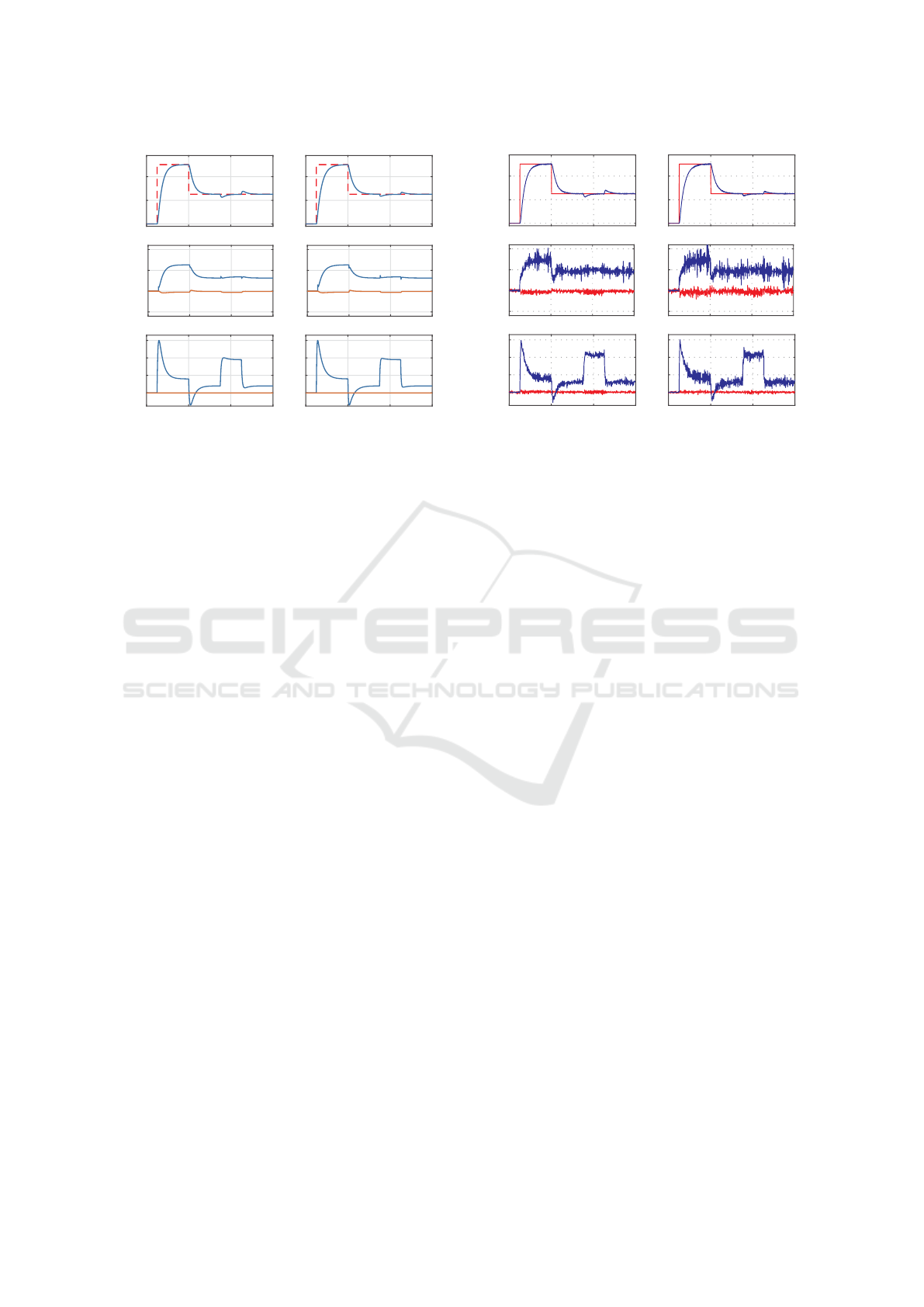
0 0.2 0.4 0.6
-0.25
0
0.25
0.5
0 0.2 0.4 0.6
0
50
100
0 0.2 0.4 0.6
0
1
2
3
0 0.2 0.4 0.6
0
1
2
3
0 0.2 0.4 0.6
-0.25
0
0.25
0.5
0 0.2 0.4 0.6
0
50
100
ω
mref
ω
m
ω
mref
ω
m
i
q
i
d
i
q
i
d
u
sq
u
sd
u
sq
u
sd
t [s] t [s]
a)
b)
ω
m
[rad/s]
i
d
i
q
[A] u
sd
u
sq
[V]
Figure 6: Simulation responses of the PMSM with SFC
coefficients found by using ABC algorithm with: a) DR
technique, b) AL technique.
ces of ABC algorithm are near the global minimum,
the most of new food sources are rejected by DR, be-
cause these violate constraints. Taken decisions about
new food source for both C-H techniques are shown
in Fig. 5.
The comparison of simulation results obtained for
PMSM with SFC tuned by ABC with DR and AL C-
H techniques is shown in Fig. 6. Result of experi-
ment carried out with the same reference signals (i.e.
values of angular speed and load torque) on physical
drive is presented in Fig. 7. From simulation and ex-
perimental responses it can be seen, that all control
objectives are fulfilled. Angular speed is controlled
without steady-state error and load torque imposed
on the PMSM shaft for t ∈ (0.35; 0.45) s is properly
compensated. Recorded waveforms of current space
vector components clearly illustrate, that zero d-axis
control strategy is successfully employed and both C-
H techniques imposed on q-axis current work well (its
maximum value does not exceed rated one).
5 CONCLUSION
This paper presented comparison of popular
constraint-handling techniques: Deb’s rules and Aug-
mented Lagrangian used with novel, nature-based
Artificial Bee Colony algorithm to solve practical
engineering problem, which is auto-tuning of SFC for
PMSM. Both C-H techniques have been successfully
used. These allow to satisfy imposed constraints
and to return a feasible solution. DR technique
owes its popularity to lack of parameters and easy
implementation. AL technique requires selection of
several parameters for proper optimization, but in
0 0.2 0.4 0.6
0
50
100
0 0.2 0.4 0.6
-0.25
0
0.25
0.5
0 0.2 0.4 0.6
0
1
2
3
0 0.2 0.4 0.6
0
50
100
0 0.2 0.4 0.6
-0.25
0
0.25
0.5
0 0.2 0.4 0.6
0
1
2
3
ω
m
[rad/s]
i
d
i
q
[A] u
sd
u
sq
[V]
t [s] t [s]
a)
b)
ω
mref
ω
m
ω
mref
ω
m
i
q
i
d
u
sd
u
sq
i
q
i
d
u
sd
u
sq
Figure 7: Experimental responses of the PMSM with SFC
coefficients found by using ABC algorithm with: a) DR
technique, b) AL technique.
this paper the recommended default parameters have
been used. In AL technique a frequency of parameter
updating should also be chosen, what was done by
using trial-and-error approach. Stability and perfor-
mance of obtained solution compensates additional
parameters that need to be chosen individually for
problem. On the basis of simulation and experimental
results, it was found that AL technique allows to find
a better solution and also to reduce standard deviation
between runs.
Regardless of employed C-H technique, obtained
weighting matrices assure steady-state error-free ope-
ration of the drive and satisfactory dynamical beha-
vior. To the best our knowledge, Augmented Lagran-
gian technique for auto-tunning of SFC was not pre-
sented before. On the basis of obtained results, we
recommend to use AL C-H technique in ABC algo-
rithm for the discussed problem.
REFERENCES
Abrahamsen, F., Blaabjerg, F., and Pedersen, J. K. (2000).
Efficiency improvement of variable speed electrical
drives for hvac applications. In Energy Efficiency Im-
provements in Electronic Motors and Drives, pages
130–135. Springer.
Andreani, R., Birgin, E. G., Mart
´
ınez, J. M., and Schuverdt,
M. L. (2007). On augmented Lagrangian methods
with general lower-level constraints. SIAM J. Optim.,
18(4):1286–1309.
Birgin, E. G. and Mart
´
ınez, J. M. (2008). Improving ulti-
mate convergence of an augmented Lagrangian met-
hod. Optim. Method Softw., 23(2):177–195.
Chan, C. C. (1993). An overview of electric vehicle techno-
logy. Proc. of the IEEE, 81(9):1202–1213.
Comparison of Constraint-handling Techniques Used in Artificial Bee Colony Algorithm for Auto-Tuning of State Feedback Speed
Controller for PMSM
275

Dai, Y., Song, L., and Cui, S. (2007). Development of pmsm
drives for hybrid electric car applications. IEEE Trans.
Magn., 43(1):434–437.
Deb, K. (2000). An efficient constraint handling method for
genetic algorithms. Comput. Meth. Appl. Mech. Eng.,
186(2-4):311–338.
Franklin, G. F., Powell, J. D., and Workman, M. L. (1998).
Digital control of dynamic systems. Addison-Wesley
Menlo Park, CA.
Gionfra, N., Sandou, G., Siguerdidjane, H., Loevenbruck,
P., and Faille, D. (2017). A novel distributed particle
swarm optimization algorithm for the optimal power
flow problem. In IEEE CCTA Conf., pages 656–661.
Grzesiak, L. M. and Tarczewski, T. (2011). Permanent mag-
net synchronous motor discrete linear quadratic speed
controller. In 2011 IEEE ISIE Symp., pages 667–672.
Grzesiak, L. M. and Tarczewski, T. (2012). PMSM ser-
vodrive control system with a state feedback and a
load torque feedforward compensation. COMPEL,
32(1):364–382.
Hestenes, M. R. (1969). Multiplier and gradient methods.
J. Optim. Theory Appl., 4(5):303–320.
Kaminski, M. and Najdek, K. (2018). Adaptive neural con-
troller based on RBF model applied for electrical drive
with PMSM motor. Przeglad Elektrotechniczny, pages
94–98 (in Polish).
Karaboga, D. and Basturk, B. (2007). A powerful and ef-
ficient algorithm for numerical function optimization:
artificial bee colony (ABC) algorithm. J. Glob. Op-
tim., 39(3):459–471.
Karaboga, D. and Basturk, B. (2008). On the performance
of artificial bee colony (ABC) algorithm. Appl. Soft.
Comput., 8(1):687–697.
Khalilpourazari, S. and Khalilpourazary, S. (2018). Opti-
mization of production time in the multi-pass milling
process via a robust grey wolf optimizer. Neural Com-
puting and Applications, 29(12):1321–1336.
Lin, F.-J., Shieh, H.-J., Shieh, P.-H., and Shen, P.-H. (2006).
An adaptive recurrent-neural-network motion control-
ler for X-Y table in CNC Machine. IEEE Trans. Syst.
Man Cybern. Part B-Cybern., 36(2):286–299.
Liu, X., Chen, H., Zhao, J., and Belahcen, A. (2016). Re-
search on the performances and parameters of interior
pmsm used for electric vehicles. IEEE Transactions
on Industrial Electronics, 63(6):3533–3545.
Long, W., Liang, X., Cai, S., Jiao, J., and Zhang, W. (2017).
An improved artificial bee colony with modified aug-
mented Lagrangian for constrained optimization. Soft
Comput.
Mezura-Montes, E. and Coello, C. A. C. (2011). Constraint-
handling in nature-inspired numerical optimization:
past, present and future. Swarm Evol. Comput.,
1(4):173–194.
Powell, M. (1967). ”A method for non-linear constraints in
minimization problems”. Atomic Energy Res. Estab.
Theoretical Physics Div. ; AERE TP 310. U.K.A.E.A.
Rockafellar, R. T. (1974). Augmented lagrange multi-
plier functions and duality in nonconvex program-
ming. SIAM J. Control, 12(2):268–285.
Senberber, H. and Bagis, A. (2017). Fractional pid con-
troller design for fractional order systems using abc
algorithm. In Electronics, 2017, pages 1–7. IEEE.
Szczepanski, R., Erwinski, K., and Paprocki, M. (2017).
Accelerating PSO based feedrate optimization for
NURBS toolpaths using parallel computation with
OpenMP. In 22nd Int. MMAR Conf., pages 431–436.
Tarczewski, T. and Grzesiak, L. M. (2016). Constrained
state feedback speed control of PMSM based on mo-
del predictive approach. IEEE Trans. Ind. Electron.,
63(6):3867–3875.
Tarczewski, T. and Grzesiak, L. M. (2018). An applica-
tion of novel nature-inspired optimization algorithms
to auto-tuning state feedback speed controller for
PMSM. IEEE Trans. Ind. Appl., 54(3):2913–2925.
Wang, X., Ufnalski, B., and Grzesiak, L. M. (2016). Adap-
tive speed control in the PMSM drive for a non-
stationary repetitive process using particle swarms.
In Compatibility, Power Electronics and Power Engi-
neering (CPE-POWERENG), 2016 10th International
Conference on, pages 464–471. IEEE.
ICINCO 2018 - 15th International Conference on Informatics in Control, Automation and Robotics
276
