
A Software Product Line Approach to Designing
End User Applications for the Internet of Things
Vasilios Tzeremes and Hassan Gomaa
Department of Computer Science, George Mason University, Fairfax, Virginia, U.S.A.
Keywords: Internet of Things (IoT), Software Product Lines, End User Development, Smart Spaces, Variability
Modeling, Software Product Line Architecture.
Abstract: The ubiquity of the Internet of Things (IoT) has made a big impact in creating smart spaces that can sense
and react to human activities. The natural progression of these spaces is for end users to create customized
applications that suit their everyday needs. One of the shortcomings of the current approaches is that there is
a lack of reuse and end users have to design from scratch similar applications for different smart spaces,
which leads to duplication of effort and software quality issues. This paper describes a systematic approach
for adopting reuse in IoT by using Software Product Line (SPL) concepts while using design patterns
relevant to these environments. In detail the paper describes the End User (EU) SPL process that can be
used to design EU SPLs for IoT environments and derive applications for different smart spaces. A Smart
Home case study is discussed to illustrate the inner workings of the EU SPL process for IoT applications.
1 INTRODUCTION
The Internet of Things (IoT) is a paradigm where
every-day physical objects (sensors, devices,
vehicles, buildings) can be equipped with
identifying, sensing/actuating, storing, networking
and processing capabilities that will allow them to
communicate with other devices and services over
the Internet to accomplish an objective (Whitmore
et al. 2015). The growing adoption of IoT has
contributed to the advancement of smart spaces.
Smart spaces are environments equipped with visual
and audio sensing, pervasive devices, sensors, and
networks that perceive and react to people, sense on-
going human activities and respond to them (Singh
et al. 2006). End User Development (EUD)
environments for smart spaces enable end users to
take advantage of device connectivity and end user
oriented user interfaces to develop applications such
as scheduling tasks, convenience through
automation, energy management efficiency, health
and assisted living (Rashidi and Cook 2009).
End User SPLs for smart spaces provide a
lightweight approach for SPL development in IoT,
while addressing the dynamic nature of these
environments. The focus of this research is to create
EU SPLs that extend heterogeneous EU architectu-
res to create a family of applications that are then
customized for different smart spaces (Tzeremes and
Gomaa 2018). Some of the benefits of EU SPLs are
that it can improve quality since the design of EU
applications is more systematic than adhoc
approaches. In addition by adopting reuse, end users
would avoid duplicating the work of others to create
similar applications.
This paper describes applying the EU SPL
approach to the design of IoT applications for
smart spaces by using SPL concepts and IoT
related design patterns. An example of a smart
home case study is used to illustrate the approach.
Section 2 provides an overview of the EU SPL
process to create product lines for IoT
environments. Section 3 describes the Smart Home
case study used to validate this research. Section 4
demonstrates how End User SPL Engineering was
applied to the Smart Home case study. Section 5
demonstrates how End User Application
Engineering is applied to derive IoT applications
from the Smart Home SPL. Section 6 describes the
evaluation of an EU SPL Prototype for the Smart
Home case study. Section 7 compares this research
with related work. Finally, section 8 provides
conclusions and discusses future work.
656
Tzeremes, V. and Gomaa, H.
A Software Product Line Approach to Designing End User Applications for the Internet of Things.
DOI: 10.5220/0006904906560663
In Proceedings of the 13th International Conference on Software Technologies (ICSOFT 2018), pages 656-663
ISBN: 978-989-758-320-9
Copyright © 2018 by SCITEPRESS – Science and Technology Publications, Lda. All rights reserved
2 EU SPL PROCESS FOR IoT
APPLICATIONS
The EU SPL process provides a systematic approach
for EU SPL designers, who can be technical end
users and/or domain experts, working with
professional software engineers, to design and
develop EU SPLs for smart spaces that end users can
use to derive applications for their environments.
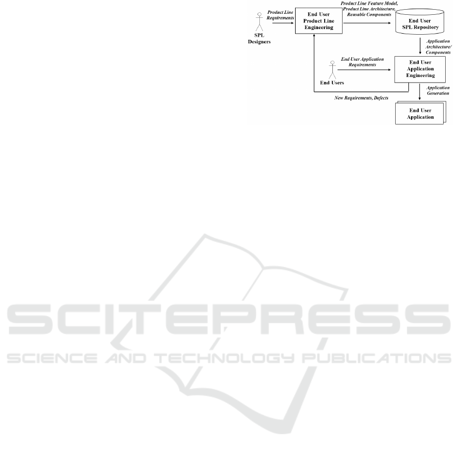
Figure 1 shows the EU SPL process. Similar to
conventional SPL engineering processes (Gomaa
2005), the EU SPL process consists of two sub-
processes: (a) the End User Product Line
Engineering (EUPLE) process in which the end user
software product line is created, and (b) the End
User Application Engineering (EUAE) process in
which software applications are derived.
2.1 End User Product Line
Engineering
The EUPLE process is composed of five phases:
Requirements elicitation, EU Analysis modeling, EU
Design modeling, EU SPL Implementation and EU
SPL Testing.
During requirement elicitation, the
product line features are defined. Product line
features are requirements or characteristics that are
provided by one or more members of the SPL
(Gomaa 2005). Feature modeling is used to capture
feature commonality / variability and feature
dependencies within the EU SPL. In addition, as part
of this research, feature modeling was extended to
capture feature dependencies in EUD environments
(platforms) (Tzeremes and Gomaa 2016a) e.g., TeC
(Sousa 2010), Jigsaw (Humble et al. 2003). Product
line features can be (a) platform independent, or (b)
platform specific to indicate whether a feature
depends on components or functionalities of a
specific EUD environment. Furthermore features
can be common, optional or alternative. Feature
groups are used for grouping similar features.
EU SPL Analysis modeling consists of static
modeling, component structuring, and dynamic
modeling. The EU SPL static model captures the
product line components needed to realize the
feature model. In addition, component structuring is
performed to capture the component reuse
stereotype, role stereotype and platform
dependencies. This research used UML stereotypes
to classify the EU SPL components. To capture
component reuse characteristics, the following reuse
stereotypes are used: «kernel», «optional»,
«variant», «default». This research uses the PLUS
Figure 1: End User Software Product Line Process.
method role stereotypes to capture the application
purpose of each component (Gomaa 2005). For
example, a component can be «entity», «timer», etc.
Components that are only applicable to specific
EUD environments are annotated with the
«platform-specific» stereotype. Dynamic modeling
is used to capture the component interactions needed
to satisfy EU SPL features. UML sequence diagrams
are used to model component interactions (Gomaa
2016) and are developed for all features defined in
the EU SPL feature model.
EU SPL Design modeling maps the EU SPL
Analysis model to the solution domain (Gomaa
2016). During EU SPL Design modeling, the
component inter-feature communication, component
relationships and component interface models are
defined. UML component diagrams are used by EU
SPL designers to capture: (a) components available
in a smart home, (b) component relationships, and
(c) provided and required interfaces needed for
components to communicate with each other. The
components are decorated with UML reuse
stereotypes to indicate whether a component is
kernel, optional, or variant. Furthermore additional
stereotypes are used to capture the role of each
component. For instance, a component can be is a
«message-broker» component, a «coordinator»
component etc. The interconnections between
components also indicate the required and provided
interfaces between components.
2.2 End User Application Engineering
During End User Application Engineering,
individual EU applications are derived from the EU
SPL and deployed. First, end users specify the
required EU SPL features for their spaces. Based on
the feature selection, the feature model is derived.
The End User Application Derivation process is
responsible for deriving the end user application
based on the feature model. In detail, the
A Software Product Line Approach to Designing End User Applications for the Internet of Things
657

components, component connectors, and component
configuration parameters that realize the selected
features are derived from the EU SPL Repository to
create the application architecture. End User
Application Testing is performed to test the selected
features, feature combinations, components and
component interactions. The End User Application
Deployment process involves end users deploying
the derived applications to their smart spaces.
During application deployment, EUD environments
map and deploy the derived application to a set of
devices available in the smart space.
3 SMART HOME CASE STUDY
The Smart Home EU SPL case study is an
application of IoT concepts integrated with end user
SPL development concepts. Smart homes are
physical environments equipped with sensors,
actuators, appliances and devices that can react
proactively or reactively to environment changes.
End User Development (EUD) environments for
smart homes integrate sensors, actuators, appliances
and devices and provide end user friendly interfaces
to allow ordinary end users to create applications for
their environments. As smart homes evolve and get
additional instrumentation, they become more
complex and difficult for ordinary end users to create
software applications. By adopting the EU SPL
process, advanced end users and domain experts can
develop end user SPLs for smart homes. Ordinary
end users can then select features from the EU SPL
to derive and deploy applications for their smart
homes. The Smart Home EU SPL case study is for a
complex smart home that includes features from the
domains of home automation, home security, home
notifications, home maintenance, resident comfort
and energy conservation.
4 END USER SPL ENGINEERING
FOR A SMART HOME
This section describes the approach to design an EU
SPL for a smart home, including feature modeling,
analysis modeling and design modeling.
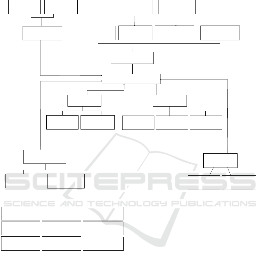
4.1 Smart Home Feature Model
Feature modeling is used to capture feature
commonality / variability and feature dependencies
within the EU SPL. Figure 2 depicts the feature
model for the Smart Home EU SPL case study,
which has one common feature called Smart Home
that all other features and feature groups depend on.
There is one optional feature Smart Irrigation and
two other optional features, Schedule and Smart
Weather Sensing, which depend on the Smart
Irrigation feature. There is one exactly-one-of
feature group called Phone Alert that has two
mutually exclusive features, namely the Audio
default feature and the Video alternative platform
specific feature. Default features are selected
automatically if no other feature in the group is
selected. The feature model also contains two at-
least-one-of feature groups: Net Notification and
Home Security. The Net Notification feature group
contains two optional features Email and Text,
which is the default feature. The Home Security
feature group contains three optional features: Door,
Motion and Window, of which Door is the default
feature. The Smart Home feature model also
contains two zero or more feature groups: Water
Detector and Home Behavior. The Water Detector
feature group contains two optional features Faucet
Drip and Flood Detector. The Home Behavior
feature group contains four optional features: Power
Failure, HVAC Filter, Light Failure and 911. In
addition the Home Alarm optional feature depends
on the Light Failure feature while the Energy
Conservation optional platform specific feature
depends on the HVAC Filter.
4.2 EU SPL Analysis Modeling
Smart Home components are categorized according
to their reuse, role and platform dependency
characteristics, which are depicted using UML
stereotypes. From a SPL reuse perspective,
components can be kernel, optional or variant. The
role perspective identifies the purpose of the
component. For example the securityAlertHandler
component shown in Figure 3 is annotated with the
«kernel» stereotype to identify the reuse category and
the «message-broker» stereotype to identify the
component role. Similarly the component videoCall
is annotated with the «optional» stereotype to capture
the reuse category, the «input / output» stereotype to
capture the role category and the «platform-specific»
stereotype to indicate that this component only
applies to specific platforms.
EU SPL designers use
dynamic modeling to capture the component
interactions needed to satisfy EU SPL features.
Sequence diagrams are used to model the message
interaction of components that support each feature.
ICSOFT 2018 - 13th International Conference on Software Technologies
658
<<common feature>>
Smart Home
<<at-least-one-of
feature group>>
Home Security
<<default feature>>
Door
<<optional feature>>
Motion
<<optional feature>>
Window
<<optional feature>>
Power Failure
<<optional feature>>
HVAC Filter
<<optional feature>>
Light Failure
<<optional feature>>
Home Alarm
<<optional feature>>
911
<<platform-specific>>
<<optional feature>>
Energy Conservation
<<optional feature>>
Faucet Drip
<<optional feature>>
Flood Detector
<<optional feature>>
Smart Irrigation
<<optional feature>>
Schedule
<<optional feature>>
Smart Weather Sensing
requires
<<default feature>>
Audio
<<platform-specific>>
<<alternative feature>>
Video
<<exactly-one-of
feature group>>
Phone Alert
<<optional feature>>
Email
<<default feature>>
Text
requires
requires
<<at-least-one-of feature
group>>
Net Notification
<<zero-or-more-of
feature group>>
Water Detector
<<zero-or-more-of
feature group>>
Home Behavior
requires
requires
requires
requires
requires
requires
requires
Figure 2: Smart Home EU SPL Feature Model.
<<kernel>>
<<message-broker>>
informationalAlertHandler
<<kernel>>
<<message-broker>>
securityAlertHandler
<<optional>>
<<coordinator>>
alertAudio
<<platform-specific>>
<<optional>>
<<input/output>>
videoCall
<<platform-specific>>
<<optional>>
<<coordinator>>
cameraManager
<<optional>>
<<coordinator>>
alertVideo
<<platform-specific>>
<<optional>>
<<input/output>>
camera
<<optional>>
<<coordinator>>
breakInMotion
<<optional>>
<<input/output>>
phone
Figure 3: Smart Home Component Structuring Subset.
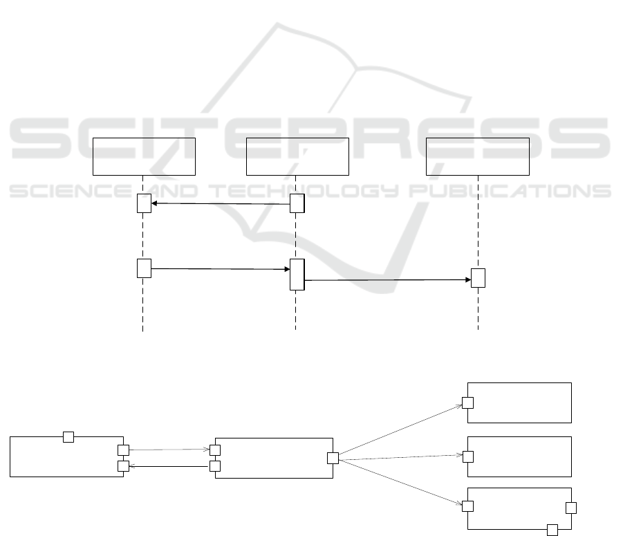
If an optional feature depends on another feature,
such as the common feature Smart Home, then the
sequence diagram depicts the components that realize
the optional feature in addition to the component(s)
that realize the common feature. Figure 4 shows the
sequence diagram of the Audio feature that involves
the optional alertAudio coordinator component
subscribing to the kernel securityAlertHandler
component and later receiving a notification to make
a call to the optional phone component.
4.3 EU SPL Design Modeling
EU SPL Design modeling maps the EU SPL
Analysis model to the solution domain (Gomaa
2016). During EU SPL Design modeling, composite
structure diagrams are developed for each feature
that depict components, component provided and
required interfaces, and component interconnections.
This notation facilitates the depictions of the
interconnection of components that support related
features, e.g., to depict components that support a
derived application. In addition to depicting
components and their stereotypes, the components
that support a Smart Home feature can be
categorized according to the design pattern that they
realize.
The following design patterns are described for a
smart home application but are sufficiently general
that they can be applied to other IoT applications:
• Sensor detection pattern. This pattern consists
of an input component receiving an event from
a sensor and notifying a coordinator
component, e.g., the doorMonitor input
component notifying the breakInDoor
coordinator component of the door sensor
detecting door movement.
A Software Product Line Approach to Designing End User Applications for the Internet of Things
659
• Actuator activation pattern. This pattern
consists of a coordinator component that sends
an event to an output component to activate an
actuator, e.g., the alertAudio sending a
makeCall event to the phone component.
• Subscription/notification pattern. This pattern
consists of message broker components that
receive events from components that monitor
the external environment and then notify
multiple subscriber components, e.g., the smart
home feature is realized by the securityAlert
and informationAlertHandler message broker
components that receive subscriptions from
client components and send notifications to
multiple subscriber components.
• Controlled activation pattern. This pattern
consists of a coordinator component that
receives an event notification and then
activates multiple actuators either in sequence
or in parallel, or some combination thereof.
e.g., the alarmHome component sending
commands to the smartAudio, smartDisplay
and smartLight output components.
• Periodic alert. This pattern consists of a
component that periodically sends a timer
event to either monitor a sensor or activate an
actuator, e.g., the sprinkerTimer component
periodically alerting the sprinkerControl to
activate a sprinkler.
UML component diagrams are used by EU SPL
designers to capture (a) components available in a
smart home, and (b) component interconnections.
The components diagrams are developed based on
the sequence diagrams developed during EU SPL
Analysis phase. Figure 5 depicts the component
diagram of the Home Alarm Feature, which is
composed of the securityAlertHandler, alarmHome,
smartAudio, smartDisplay and smartLight
components. The components are depicted with
UML stereotypes to indicate whether a component is
kernel, optional, or variant, e.g., the
securityAlertHandler is a «kernel» component while
the other four components are «optional».
Furthermore additional stereotypes capture the role
of each component, e.g., securityAlertHandler is a
«message-broker» component. Components can also
have a multiplicity indicator to indicate the number
of component instances in a smart space, e.g,. the
smartAudio component has 1…* multiplicity that
indicates there can be more than one instance in the
smart space.
<<optional>>
<<coordinator>>
:alertAudio
<<optional>>
<<input/output>>
:phone
makeCall
[call=true]
<<kernel>>
<<message-broker>>
:securityAlertHandler
subscribe
[sendAlert=true]
[init=true]
notify
Figure 4: Sequence Diagram for the Smart Home EU SPL Audio Feature.
<<optional>>
<<input/output>>
smartAudio
<<optional>>
<<input/output>>
smartDisplay
<<optional>>
<<input/output>>
smartLight
play
show
flash
alarm
<<optional>>
<<coordinator>>
alarmHome
init
notify
<<kernel>>
<<message-broker>>
securityAlertHandler
sendAlert
subscribe
receiveAlert
setLightLevel
replace
1..*
1..*
1..*
Figure 5: Component diagram of the Home Alarm Feature
ICSOFT 2018 - 13th International Conference on Software Technologies
660
5 SMART HOME END USER
APPLICATION ENGINEERING
Application engineering is utilized by end users to
derive applications for their smart spaces. An
application derivation example is shown from the
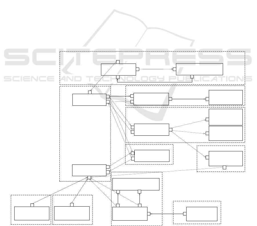
Smart Home EU SPL. Figure 6 shows in dashed
boxes the features selected for a derived application
from the Smart Home EU SPL. The selected features
follow the SPL feature dependency and feature
group consistency rules. For example there is only
one feature selected from the “Phone Alert” exactly-
one-of feature group, there is one feature selected
from the “Home Security” and “Net Notification” at-
least-one-of feature groups. Some examples of
feature dependency are the “Smart Home” common
feature that all other features depend on, the “Light
Failure” feature that the “Home Alarm” depends on
and the “Smart Irrigation” feature that the
“Schedule” feature depends on. Figure 6 also shows
components selected and interconnected for the
derived Smart Home application for clarity the
dashed boxes depict the feature boundaries for the
components that realize the features. The common
Smart Home Feature is supported by a
subscription/notification design pattern and consists
of two message broker components. The Door,
Flood Detector, and HVAC filter optional features
are mapped to sensor detection design patterns and
consist of optional input components, e.g.,
doorMonitor that receive inputs from external
sensors. The Audio, Home Alarm and Sprinkler
Irrigation optional features are mapped to controlled
activation patterns that consist of optional
coordinator components that control optional output
components, e.g., smartAudio, which activates and
deactivates external actuators.
6 VALIDATION
To validate this research, a smart home EU SPL case
study was created with 24 common and variant
features organized in different feature groups. In
addition, 32 kernel, optional and variant components
were created to realize these features. The case study
was developed following the EU SPL Engineering
process. In particular, the EUPLE process was used
to design and develop the case study and the EUAE
process was used to derive applications.
<<optional>>
<<coordinator>>
breakInDoor
<<optional>>
<<input/output device interface>>
doorMonitor
activate
on
movementaction
activity
1..*
<<optional>>
<<coordinator>>
alertAudio
notify
<<default>>
<<input/output>>
phone
makeCall
call
init
<<kernel>>
<<message-broker>>
securityAlertHandler
sendAlert
subscribe
receiveAlert
<<optional>>
<<input/output>>
smartAudio
<<optional>>
<<input/output>>
smartDisplay
<<optional>>
<<input/output>>
smartLight
play
show
flash
alarm
<<optional>>
<<coordinator>>
alarmHome
init
notify
<<kernel>>
<<message-broker>>
infoAlertHandler
sendAlert
subscribe
receiveAlert
flood
<<optional>>
<<input/output>>
flood-sensor
1..*
<<optional>>
<<system-interface>>
text
notify
init
replace
<<optional>>
<<input/output>>
smartHVAC
replace filter
1..*
1..*
1..*
1..*
<<optional>>
<<coordinator>>
sprinklerControl
<<optional>>
<<input/output>>
sprinkler
turn on
turn off
startWater
stopWater
1..*
<<optional>>
<<timer>>
sprinklerTimer
timeAlert
water
Schedule Feature
Smart Irrigation Feature
Flood Detector
Feature
HVAC Filter
Feature
Smart Home Feature
Door Feature
Text Feature
Audio Feature
Home Alarm
Feature
Light Failure Feature
Figure 6: Example of Smart Home Application Architecture.
A Software Product Line Approach to Designing End User Applications for the Internet of Things
661

The End User Software Product Line Prototype
(EUSPLP) development environment was created to
validate this research. The EUSPLP environment
was designed to support end users and extend EUD
environments for smart spaces. EU SPL designers
create the EU SPL through the EUSPLP web
interface. End users also utilize the EUSPLP web
interface to derive applications for their spaces.
Currently EUSPLP is used to derive applications for
TeC EUD environments. The derived applications
were deployed to the TeC Android simulator (Sousa
et al. 2012).
The simulator allows tests at runtime on
derived applications before they are deployed to a
hardware platform. In addition derived applications
were deployed in a physical environment using X10
hardware (Tzeremes and Gomaa 2016b).
As part of this research, a testing framework was
developed to test EU SPLs and derived applications
developed using the EUSPLP environment. The
framework was used to perform EU SPL Testing,
EU Application Testing and EU Application
Deployment Testing. During EU SPL Testing, EU
SPL Feature-based Consistency and Feature-based
Integration test cases were used to test the EU SPL.
Feature-based Consistency testing consisted of
executing static test cases to verify feature and
feature group dependencies. Feature-based
Integration consisted of integration test cases to test
the EU SPL. During EU Application testing, EU
Application Feature-based Consistency and Feature-
based Integration test cases derived from the EU
SPL were used to test the derived applications.
During EU Application Deployment Testing,
Feature-based Integration tests were also executed
on the deployed application to ensure successful
application deployment.
The smart home case study was created using the
EUSPLP environment and was tested using the EU
SPL Testing approach. 34 Feature-based
Consistency test cases and 79 Feature-based
Integration test cases were developed and
successfully executed. The derived EU Application
was also tested using derived EU Application
deployment test cases to ensure that the deployment
was successful. All test cases executed on features
and components of the case study and derived
applications were successful.
7 RELATED WORK
Our research builds on prior work in IoT, EUD
environments for smart spaces, SPL methods, and
current SPL approaches for end users and smart
spaces. In IoT, smart objects are everyday objects
that are equipped with hardware components such as
a radio for communication, a CPU to process tasks,
sensors/actuators to be conscious of the world in
which they are situated and to control it at a given
instance (Fortino and Trunfio 2014). This paper has
described an EU SPL approach that can be used in
IoT smart spaces. Several EUD environments for
smart spaces have been developed over the years to
enable end users to create software applications for
their environments. Some notable examples are
Jigsaw (Humble et al. 2003). PIP (Chin et al. 2010),
FedNet (Kawsar et al. 2008), and TeC (Sousa 2010).
Typical EUD environments for smart spaces do not
address reuse. End user applications are created for
specific environments and are not portable to other
environments. In contrast, our approach extends
existing EUD environments for smart spaces with
SPL support. SPL methods such as PLUS (Gomaa
2005), and KobrA (Atkinson and Muthig 2002)
address the problem of modeling variability in SPLs.
The research described in this paper has extended
current SPL approaches to provide support for EUD
development and smart spaces. Current research on
utilizing SPL concepts for end users and smart
spaces includes SimPL (Malaer and Lampe 2008)
and Perez et al.(Perez and Valderas 2009). Our
research extends Perez’s work beyond requirements
elicitation for SPLs by utilizing visual languages and
application models of EUD environments to create
SPLs for smart spaces.
8 CONCLUSIONS AND FUTURE
WORK
The IoT has made a big impact in creating smart
spaces, such as smart homes that can sense and react
to human activities. As IoT environments become
pervasive, end users are expected to develop
customized software to suit their needs. Even though
there are several end user development tools, not all
end users have the technical skills to use these tools.
Moreover, there have been several software quality
issues with applications created by end users. By
adopting SPL concepts, software quality could be
improved since software would be created once and
then reused by several end users.
This paper has described a systematic approach
for designing EU SPLs for IoT that utilizes IoT
specific design patterns, from which end users can
derive IoT applications for their smart spaces. The
End User Product Line Engineering (EUPLE)
ICSOFT 2018 - 13th International Conference on Software Technologies
662

process for designing, developing and testing EU
SPLs for smart spaces extends conventional SPL
Engineering approaches (Gomaa 2005) to end user
development and smart spaces. The End User
Application Engineering (EUAE) process for
deriving end user applications extends conventional
Application Engineering approaches (Gomaa 2005)
to smart spaces. This research applied the EU SPL
process to a Smart Home case study. The case study
SPL was implemented using the EU SPL prototype
development environment developed by this
research. Several smart home applications were
derived from the SPL and were deployed to the TeC
EUD environment for smart spaces.
Future work will apply the EU SPL approach to
other smart spaces domains and IoT applications.
Additional research needs to be conducted to create
a security meta-model that addresses the
authentication, access control, privacy and
confidentiality security attributes of smart spaces in
EU SPLs. Finally additional investigation is needed
to integrate the EUSPLP environment with
additional IoT EUD environments.
ACKNOWLEDGEMENTS
This work was partially supported by the AFOSR
grant FA9550-16-1-0030.
REFERENCES
Atkinson C., Muthig D. (2002). Component-Based
Product-Line Engineering with the UML. In: Gacek C
(ed) Software Reuse: Methods, Techniques, and Tools.
Springer Berlin / Heidelberg, pp 155–182
Chin J., Callaghan V., Clarke G. (2010). End-user
Customization of Intelligent Environments. In:
Nakashima H, Aghajan H, Augusto JC (eds)
Handbook of Ambient Intelligence and Smart
Environments. Springer US, Boston, MA, pp 371–407
Fortino G., Trunfio P. (2014). Internet of Things Based on
Smart Objects: Technology, Middleware and
Applications. Springer Publishing Company
Gomaa H. (2005). Designing Software Product Lines with
UML: From Use Cases to Pattern-Based Software
Architectures. Addison-Wesley Professional
Gomaa H. (2016). Real-Time Software Design for
Embedded Systems. Cambridge
Humble J., Crabtree A., Hemmings T., et al (2003).
Playing with the Bits User-Configuration of
Ubiquitous Domestic Environments. In: Proceedings
of the 5th International Conference in Ubiquitous
Computing. Springer LNCS, Seattle, WA, pp 256–263
Kawsar F., Nakajima T., Fujinami K. (2008). Deploy
Spontaneously: Supporting End-Users in Building and
Enhancing a Smart Home. In: Proceedings of the 10th
International Conference in Ubiquitous Computing.
Seoul, South Korea, pp 282–291
Malaer A., Lampe M. (2008) SimPL: A Simple Software
Production Line for End User Development. In: 15th
Asia-Pacific Soft. Engineering Conference. Beijing,
China, pp 179–186
Perez F., Valderas P. (2009). Allowing End-Users to
Actively Participate within the Elicitation of Pervasive
System Requirements through Immediate Visualiza-
tion. In: Proceedings of the 4th International
Workshop on Requirements Engineering Visualization.
Atlanta, Georgia, USA, pp 31–40
Rashidi P., Cook D. J. (2009). Keeping the Resident in the
Loop: Adapting the Smart Home to the User. Trans
Sys Man Cyber Part A 39:949–959.
Singh R., Bhargava P., Kain S. (2006). State of the art
smart spaces: application models and software
infrastructure. ACM Ubiquity 2006:7:2–7:9
Sousa J. P. (2010) Foundations of Team Computing:
Enabling End Users to Assemble Software for
Ubiquitous Computing. In: International Conference
on Complex, Intelligent and Software Intensive
Systems. Krakow, Poland, pp 9–16
Sousa J. P., Shen X, Tzeremes V., Hodum F. (2012) TeC
apps for smart spaces: simple, decentralized, resilient,
and self-healing. In: The 2012 ACM Conference on
Ubiquitous Computing, PA, USA, 2012. pp 637–638
Tzeremes V., Gomaa H. (2016a). A Multi-platform End
User Software Product Line Meta-model for Smart
Environments. In: Proceedings of the 11th
International Joint Conference on Software
Technologies, Lisbon, Portugal. pp 290–297
Tzeremes V., Gomaa H. (2018). Applying End User
Software Product Line Engineering for Smart Spaces.
In: 2018 51th Hawaii International Conference on
System Sciences (HICSS). pp 5756–5765
Tzeremes V., Gomaa H. (2016b) XANA: An End User
Software Product Line Framework for Smart Spaces.
In: 2016 49th Hawaii International Conference on
System Sciences (HICSS). pp 5831–5840
Whitmore A., Agarwal A., Xu L. (2015). The Internet of
Things–A Survey of Topics and Trends. Information
Systems Frontiers 17:261–274.
A Software Product Line Approach to Designing End User Applications for the Internet of Things
663
