Walking Robot Bio-inspired by Insect’s Locomotion for Carbon
Dioxide Diagnostic Indexed in the Air
Santiago Noriega Álvarez, María Camila Rojas and Hernando Leon-Rodriguez
Electronic Department, Faculty of Engineering, El Bosque University, Bogota, Colombia
Keywords: Robot’s Simulation, Spider Motion, Quadruped Robots.
Abstract: The spiders, in comparison with the majority of others animals, it has the ability to access all kind of
environment where others animals or even the humans can’t. Those attributes of the spiders are taken into
this project in order to design and develop a quadruped spider robot with the ability to move in all kind of
directions and perform pre-set motions programs such as ascend, descend, obstacles avoiding and gas
detections. The paper is presented the dynamic and kinematics model with the purpose of understand how,
mathematically the quadruped animal and spiders walk. In this sense we studied the movement of a real
spider in order to define a suitable bio-mimetic locomotion model. In additions walking simulations were
implemented and the gas detection results are presented.
1 INTRODUCTION
In the recent years, human want to reproduce all
kind of movement bioinspired by the nature, given
back some successful results. The effort on try to
understanding and analyse the locomotion behaviour
allowed novel mathematical models. All this models
can be used in robotics for certain task instead of
risk human lives. This kind of biomimetic
replication can be employed in, as example, land
mines task, exploration task and even underwater
inspection (Zhao, 2017) Another important
application of these robots is the incursion in
dangerous environments, like contaminated places,
or hostile landmarks.
In quick evaluation into the subject at the macro-
scale Boston Dynamic’s is one research institution
or business company that design and produce a huge
variety of robots, especially quadruped ones.
(Raibert, 2008). The most popular one is Big Dog; it
is employing entirely in exploration duties.
Other approaches of walking robots
biomimetically inspired at mili-scale are based in the
insects like spider locomotion. The spider robot was
built around 90’s where researches started to
innovate the whole world with their robots. (Shoval,
1999) Now, is a big market built hexapod spider
robot, which had the ability of climb all kind of
surfaces.
Nowadays, the majority of information suggests
that the quadruped spider robots are developed by
amateurs or fans whom wants to develop a kind of
open loop control device. Other approaches are
being done by complex close loop control (Lu,
2017) or by using other mechanism for quadruped
walking like parallel mechanism (Wang, 2010), soft
materials (Garabini, 2017) and so on.
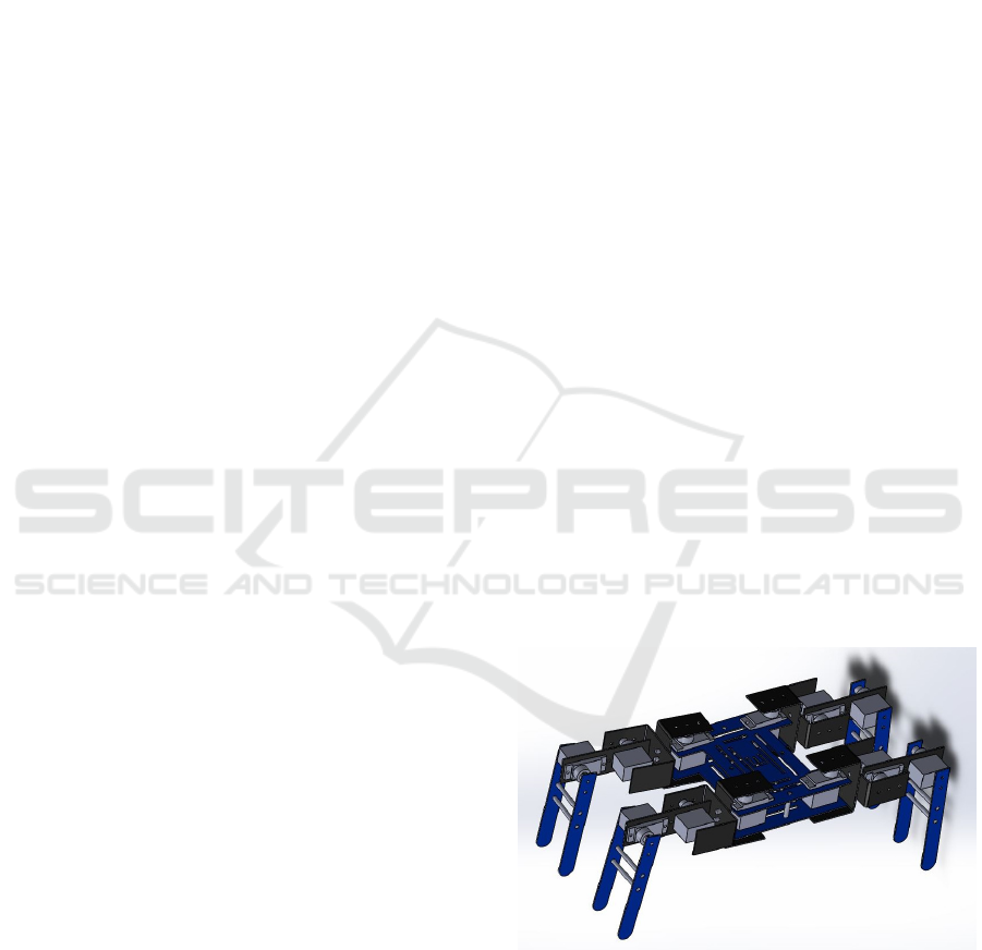
Figure 1: Quadruped robot design.
This paper presents a basic approach of one
quadruped robot with its different attributes and
characteristics showing in figures 1 and 2. Several
historical contributions had been developed by other
researches incorporating cameras, sensors, geo-
localization and so on. (Semini, 2010) This project is
a particular bio inspired robot that carry onboard gas
480
Álvarez, S., Rojas, M. and Leon-Rodriguez, H.
Walking Robot Bio-inspired by Insect’s Locomotion for Carbon Dioxide Diagnostic Indexed in the Air.
DOI: 10.5220/0006912804800486
In Proceedings of the 15th International Conference on Informatics in Control, Automation and Robotics (ICINCO 2018) - Volume 2, pages 480-486
ISBN: 978-989-758-321-6
Copyright © 2018 by SCITEPRESS – Science and Technology Publications, Lda. All rights reserved
sensor to characterize the air in a narrow and/or
constrain areas.
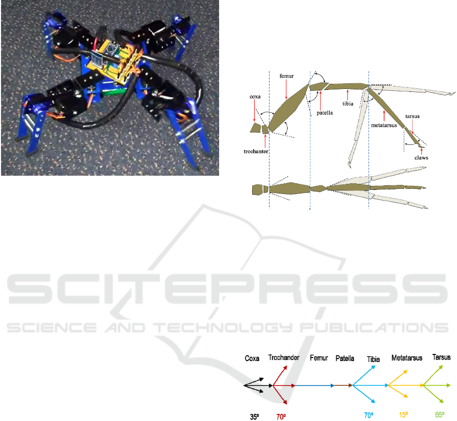
Figure 2: Quadruped robot prototype.
The movement of this robot executed the
mathematical control of forward kinematics and
evaluates the air environment for gas contamination.
2 THE QUADRUPEDS
In order to achieve this project initially observes the
behaviour of the quadruped locomotion in the
animal kind in their natural environment. The
motions and algorithms are well established, like
how they move, avoid obstacles and synchronise its
motion behind. As a result, the majority of the
quadrupeds move in a mammalian form, like a dog
or a horse, as example. This represented to follow its
complex locomotion or used a mixture of sources of
inspiration to meet the quadruped animal movement
and behaviour. On the other hand, the mili-scale
inspired the anatomy for spiders. As a result, the
anatomy, movements and physic shape of insects are
not yet well stables in the robotics field.
3 MOTION ANALYSIS
Initially, it’s important to know that the spider has 7
parts by leg (figure 3). These parts are: coxa,
trochanter, femur, patella, tibia, metatarsus and
tarsus. This spatial arrangement it’s illustrated in the
figure 4. From the original anatomy of the spider,
this project suppresses some leg’s part and
component´s joints. Based in simplification some
spider´s leg part the robot is reduced as follow:
instead of using the Patella part, we linked the femur
and the tibia by a direct joint. The metatarsus and the
tibia were united as a single link or part. Similarly,
we dismiss the tarsus. All of these dismissals were
executed in the robot, however, for kinematic
analysis and simulation we took the entirely system
for a realistic approach resulting to know which
parts can be considering redundant.
Figure 3: Spider’s leg parts.
One important aspect is the amplitude that has every
part of the spider leg. This means, for example, that
the coxa has amplitude of 35 degrees while tibia has
a mobility of 70 degrees. Also, every of the seven
components of the limb, has a different axis of
movement; for example, the trochanter has a
movement in X-Y axis, meanwhile the femur in X-Z
axis. This kind of association and motion, it’s
explained graphically in the figure 4.
Figure 4: Range of movement of the spider.
In order to establish the different joints and links
which constitute the system limb of the spider, it is
defined as follow:
• Body-Coxa joint: joint with three degrees of
freedom (DOFs) ball-and-socket joint.
• Coxa-Trochanter joint: either 3-DOFs ball-and-
socket or a 2-DOFs saddle joint.
• Trochanter-Femur joint: this modeled as a
universal joint with 2-DOFs.
• Femur-Patella joint: Commonly this joint can be
modeled as a hinge joint 1-DOF.
Walking Robot Bio-inspired by Insect’s Locomotion for Carbon Dioxide Diagnostic Indexed in the Air
481
• Patella-Tibia joint: There are two options to
model this joint; first as a hinge joint or a
universal joint with very limited joint on Y-Z
axis.
• Tibia-Metatarsus: it is also possible to assume
this joint as a hinge joint, or a universal joint but
with some constraints.
• Metatarsus-Tarsus joint: this joint can be
modeled as a universal joint.
In this case, the claws are the end-effector of the
system. This means that this part of the limb is
whom interacts with the outside.
4 MATHEMATICAL ANALYSIS
As we mentioned previously, there are some
constraints that we applied in the anatomic
development. We applied these modifications in the
mathematical development and we decided to
involve all the possible variables, based on the
following table to produces the most faithful model
and prototype.
Table 1: Limited ranges of angular rotation.
Parts Movements Plane
Coxa 75 Transversal
Femur 140 Sagittal
Tibia 40 Sagittal
4.1 Direct Kinematics
In order to study the direct kinematics of the robot at
first by using the joint variables of contact limbs,
position and orientation of the platform based on
fixed frame are determined.
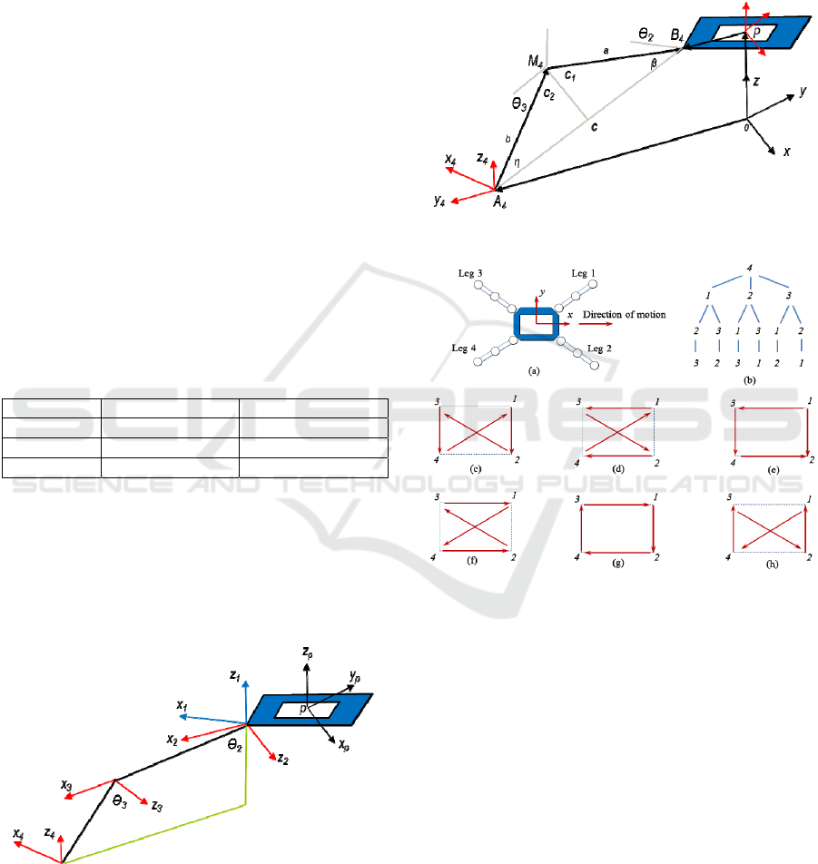
Figure 5: Coordinate frames of the robot.
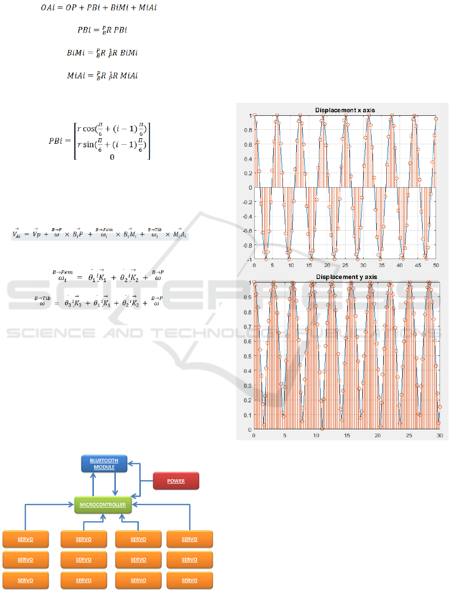
Taking into account the figure 5 and knowing OAi
vectors, which are the end points of contact legs, we
can establish the next expression:
rBi=rAi+rMi/Ai+rBi/Mi (1)
In this expression, rBi and rAi represent the position
vector of Bi. In the same way, we needed to
determinate all the parameters of the system in a
graphically mean. In the figure 6 it can be detail
these parameters.
Figure 6: Parameters of the system.
Figure 7: Quadruped walk locomotion.
Suppose that the leg 1, 2 and 3 are standing on the
ground. According to relation (1) the location of
points Bi versus fixed coordinate are determined and
as direction of x axis of P-coordinate system is direct
to B3B1 vector can determine the direction of x-axis
unit vector:
Ex=⟦B3*B1⟧/⟦B3*B1⟧ (2)
In the same way, we can determinate the vector
B3B2 as follow:
Em=⟦B3*B2⟧/⟦B3*B2⟧ (3)
By having this information, we can determinate the
direction of unit vector, normal to the platform
plane. To do this, we first needed to implement the
cross product of the two previous vectors:
ICINCO 2018 - 15th International Conference on Informatics in Control, Automation and Robotics
482
z=Em*Ex (4)
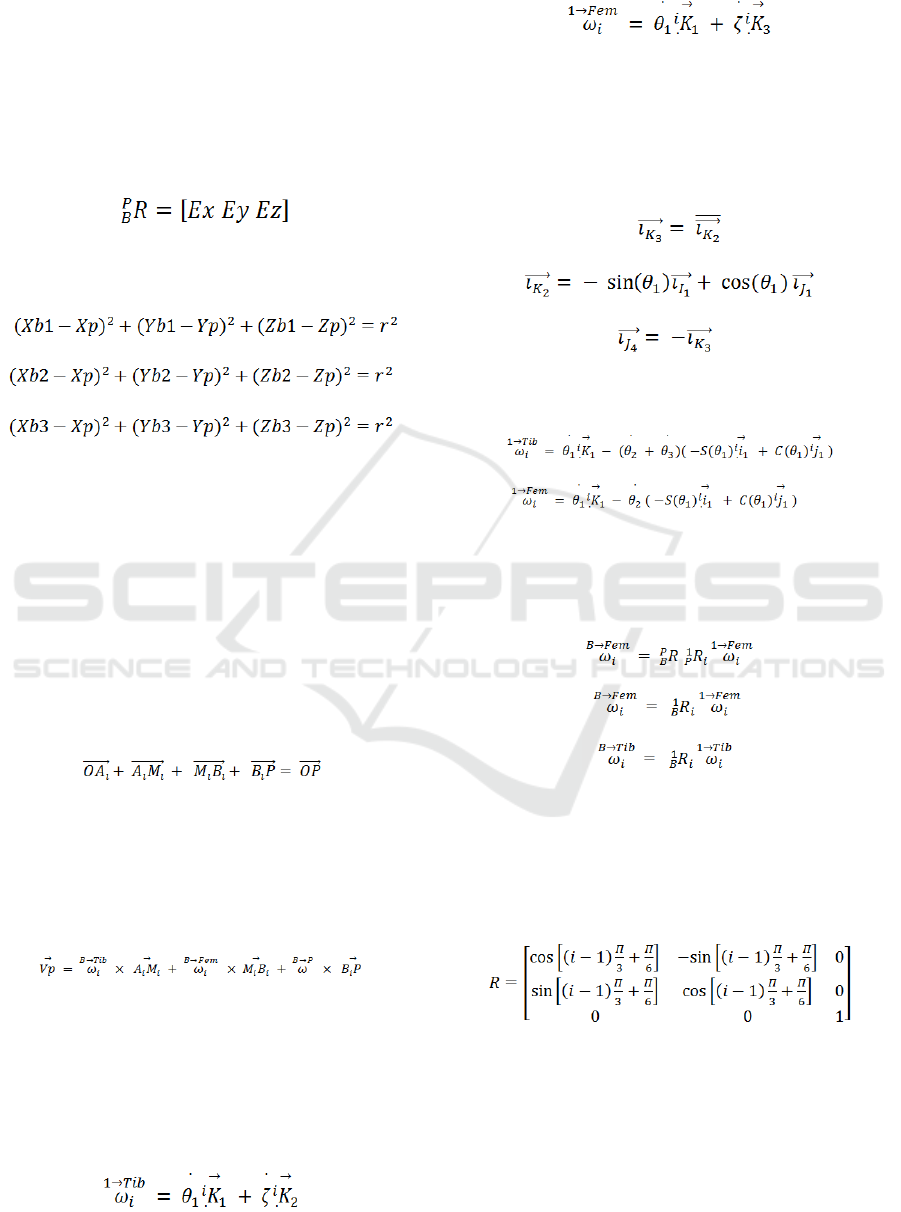
In the same way, having the vectors Ex and Ez, it’s
possible to determinate the Ey by the same method:
Ey=Ex*Ez (5)
These three vectors are necessary because we can
establish the matrix of the platform versus fixed
coordinates with the next expression:
(6)
In order to specify the origin of coordinate system,
we can use the equation of the circle in this way:
(7)
(8)
(9)
If we solve the equations system previously
established, we can determinate the position of the
body in the coordinate system.
4.2 Platform Velocity
In order to determinate the velocity of the robot’s
platform its necessary to determine the velocity and
angular velocity of robot platform by using the
position and velocity of joint variables. In order to
specify the direct kinematics of platform velocity
can use (10):
(10)
In the previous expression, OAi represents a vector
was drawn from fix coordinate origin to point “A”
from leg No. i. It’s possible to determinate the
relation between velocity of joint variables and
platform velocity by differentiating from (10). The
result is (11):
(11)
In (11), the first and third element of the equality
represents the absolute angular velocity of femur and
tibia of limb No. i respectively. If we take into
account the symmetry of our robot, (11) can be used
for the other three contact legs. By using the fifth
element of (11), it’s possible establishes Vp. Based
on figure 6:
(12)
Regarding to the figure 6:
(13)
In expression (12) and (13), the first factor in both of
them, indicates the unit vector direct to z-axis of first
coordinate frame of limb No. i. The relation between
the unit vectors of different coordinate frames of
each leg is determined in function of the figure 6 as
follow:
(14)
(15)
(16)
Using the expressions from (12) to (18), we can
determine the values of ωi as follows:
(17)
(18)
In (19) and (20) the S’s and the C’s, means cosines
and sines. In this case, for mathematical simplicity,
que can express all the previous equations as
rotational matrices as follows:
(19)
(20)
(21)
As we mentioned previously, ‘R’ represents the
rotational matrix of platform relative to fix
coordinate frame. In this order R1p is rotation matrix
of first coordinate frame of limb No.i relative to P-
coordinate frame system. This last rotational matrix
is defined as follow:
(22)
In (24) is the number of limbs.
4.3 Direct Kinematics of Non-contact
Leg
Direct kinematics of position for a non-contact limb
it’s similar to the direct kinematics for a serial robot.
Walking Robot Bio-inspired by Insect’s Locomotion for Carbon Dioxide Diagnostic Indexed in the Air
483
As shown in Fig. 7 can write:
(23)
(24)
(25)
(26)
Based on the previous expressions PBi can be
establishing as follows:
(27)
As we did with the contact legs, we wanted to
determinate the velocity of the non-contact limbs, so
the procedure is similar. We first need to
differentiate (25) as follows:
(28)
Using the information from (11):
(29)
(30)
With (30) to (32) we can determinate the velocity of
end point of noncontact legs; as a result, these values
can be specified.
5 SIMULATION AND CONTROL
Figure 8 is showing the conceptual map of robot
control based in arduino controller and Bluetooth
communication system sending and receiving
routine commands from mobile device.
Figure 8: schematic control design of quadruped robot.
Figure 9 is showing the representation of the
forward movements of each axis of the robot using
Matlab ©. We use Arduino as a controller for the
full platform control and communication. For
motion, 12 servo-actuators were set, 3 for each leg
with torque of 2.2Kg-cm. these servo-motors are
attached directly as a joint of each link-leg. The
supply voltage and current for the robot was a
battery package of 4.8 V and 3000 mA with around
power of 7.5 W approx.
Figure 9: Oscillation motion of each leg in x and y axis.
6 GAS SENSOR EVALUATION
Regarding to the reading of the carbon dioxide
index, an embedded circuit capable of monitoring
various types of gases was implemented. Thanks to
the micro-controller implemented to achieve the
movement of the spider, it was easy to incorporate
the sensor in question. The challenge was to recreate
the characteristic curve of this device through a
function based in the response with different types
of gases, figure 10.
ICINCO 2018 - 15th International Conference on Informatics in Control, Automation and Robotics
484
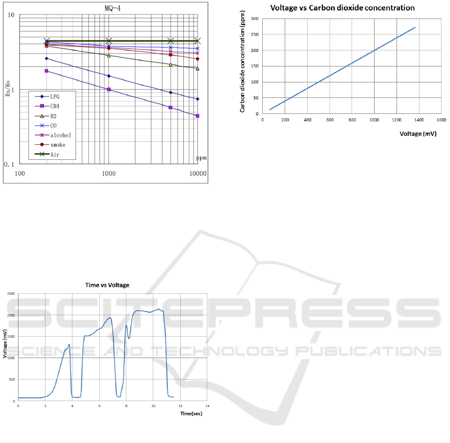
Figure 10: Gas sensor curve (MQ-4).
Initially, the characteristic curve of the sensor
was expected to have a directly proportional
relationship between the voltage at the output of the
sensor, and the carbon dioxide concentration, as
shown below.
Figure 11: Response profile MQ4, time vs voltage.
The figure 11 shows the output voltage of the
sensor depending of the gas concentration reading
by the sensor. In this order of ideas, a gas source was
arranged next to the sensor; as the gas concentration
increased, so did the voltage. Then it will show a
graph that link the voltage at the output of the
sensor, with the carbon dioxide concentration.
Figure 12 is showing the characterization of the
sensor was achieved through a linear regression
model, obtaining fairly accurate results. An
extremely important aspect to mention is the fact
that currently this issue is still being evaluated and
treated, with the purpose of implementing the sensor
that best shapes itself, and conditioning the signals
of it with the purpose of achieving the best results.
Figure 12: Voltage vs Carbon dioxide concentration.
7 CONCLUSIONS
The project had achieved step by step the design,
development and control of a quadruped walking
robot. The mathematical model helped out the
modelling of the motion´s behaviour of the robot.
The robot has achieved 12 DOF in total, 3 DOF
for each leg, controlled by an Arduino Nano via
remote mobile device. The movement has been
analysed with biomimetic inspirations take from
spider.
The gas sensor MQ4 was an excellent first
approach to the sensing technology because it
allowed characterizing the behaviour of the gas.
Additionally, these results will serve as a foundation
in future research.
REFERENCES
Garabini M., Santina C.D., Bianchi M., Catalano M.,
Grioli G., Bicchi A. (2017) Soft Robots that Mimic the
Neuromusculoskeletal System. In: Ibáñez J.,
González-Vargas J., Azorín J., Akay M., Pons J. (eds)
Converging Clinical and Engineering Research on
Neurorehabilitation II. Biosystems & Biorobotics, vol
15. Springer, Cham.
Lu Yi, Zhou Keke, Ye Nijia; 2017; Design and
kinemics/dynamics analysis of a novel climbing robot
with tri-planar limbs for remanufacturing, Journal of
Mechanical, Science and Technology, March 2017,
Volume 31, Issue 3, pp 1427–1436
Raibert Marc, Blankespoor Kevin, Nelson Gabriel, Rob
Playter and the BigDog Team; 2008; BigDog, the
Rough-Terrain Quadruped Robot, Proceedings of the
17th World Congress The International Federation of
Automatic Control Seoul, Korea, July 6-11, 2008
Semini Claudio; 2010; HyQ - Design and Development of
a Hydraulically Actuated Quadruped Robot, A thesis
Walking Robot Bio-inspired by Insect’s Locomotion for Carbon Dioxide Diagnostic Indexed in the Air
485

submitted for the degree of Doctor of Philosophy
(Ph.D.) April 2010.
Shoval S., Rimon E. and Shapiro A.; 1999 "Design of a
spider-like robot for motion with quasi-static force
constraints," Proceedings 1999 IEEE International
Conference on Robotics and Automation, Detroit, MI,
1999, pp. 1377-1383 vol.2. doi: 10.1109/
ROBOT.1999.772553
Wang Hongbo, Zhengyan Qi, Guiling Xu, Fengfeng Xi,
Guoqing Hu and Zhen Huang; 2010; Kinematics
Analysis and Motion Simulation of a Quadruped
Walking Robot with Parallel Leg Mechanism, The
Open Mechanical Engineering Journal, 2010, 4, 77-85
Zhao Tang, Peng Qi, Jian Dai, (2017) "Mechanism design
of a biomimetic quadruped robot", Industrial Robot:
An International Journal, Vol. 44 Issue: 4, doi:
10.1108/IR-11-2016-0310
ICINCO 2018 - 15th International Conference on Informatics in Control, Automation and Robotics
486
