
Improving the Joint Mobility of Acute Rotator Cuff Injury by
Portable Rehabilitation Device
Laura Jiménez Guzmán, Mariana Torrente Rocha and Hernando Leon-Rodriguez
Bio-Engineering Department, Faculty of Engineering, El Bosque University, Bogota, Colombia
Keywords: Acute Injury, Rotator Cuff Rehabilitation, External-internal Rotation, Soft-rehabilitation Robot, Portable
Robot.
Abstract: The incidence of shoulder pain in the general population is around 11.2 cases per 1,000 patients per year. It
is considered to be the most prevalent soft tissue pathology, with an estimated incidence of rotator cuff
injuries of 3.7 per 100,000 per year. The deterioration of the components of the rotator cuff is one of the
most frequent causes of musculoskeletal pain and disability in the world. The conditions of the rotator cuff
increase with the age and overuse of the joint, therefore, elderly patients are more affected. This paper
presents the development of one soft and portable rehabilitation prototype robot that aims to be evaluated
with patients in near future as a suitable device for rehabilitating acute rotator cuff injuries through clinical
examinations. The portable robot presented was design from biomechanical analysis and ranges of
kinematics and joint dynamics; aspects that determined important requirements for obtaining greater
functionality of the prototype´s portability and with the identification of pre-set tasks that executes two
types of specific movements: flexion / extension and external / internal rotation by means of a soft
rehabilitation and portable robot device.
1 INTRODUCTION
The component´s deterioration of the rotator cuff is
one of the most frequent causes of musculoskeletal
pain and disability in the world. The incidence of
shoulder pain in the general population is around
11.2 cases per 1,000 patients per year. It is
considered to be the most prevalent soft tissue
pathology, with an estimated incidence of rotator
cuff injuries of 3.7 per 100,000 per year. The rotator
cuff is composed of four muscles: supraspinatus,
infraspinatus, minor round and subscapularis, and its
functions are to offer mobility, strength and
stabilization to the glen-humeral joint, due to the
relationship between the glen-humeral ligaments and
the joint capsule. The conditions of the rotator cuff
increase with the passage of time, since they have a
direct relationship with a process of deterioration
rather than with a traumatic event, so the problem
increases with age and overuse of the joint,
therefore, elderly patients are more affected.
However, the incidence of shoulder pain in workers
reaches up to 18.3%. In order to decrease pain and
recover shoulder movement, patients are usually
treated by regular sessions with a physiotherapist.
The pathology of the rotator cuffs is associated
with the overuse of the joint, either by work, sports,
vascularity, mechanical failure located in the
supraspinatus tendon, ruptures caused by
deterioration or even by the entrapment that the
tendon suffers between the humerus and the
acromion. There are other risk factors that can lead
to a rotator cuff injury, such as obesity,
hypercholesterolemia, smoking, genetic factors,
anatomical variations, scapular dyskinesia and glen-
humeral instability. (Orth, Paré, 2017)
Rehabilitation has always been a social concern
in the fields of health study and engineering. The
effects of disability due to rotator cuff injuries
decrease a person's productivity in areas such as
population interaction, so the need for improvement
goes beyond an ideal biomechanical state.
Currently, the rehabilitation of rotator cuffs starts
from the application of conventional therapies, to the
use of robotics as alternative mechanisms, which
integrate engineering concepts such as compensation
of force, motor control at speeds calibrated
according to the motor functions of each individual
and sensory contributions that through the repetition
of exercises in intensive training programs manage
Guzmán, L., Rocha, M. and Leon-Rodriguez, H.
Improving the Joint Mobility of Acute Rotator Cuff Injury by Portable Rehabilitation Device.
DOI: 10.5220/0006913104870495
In Proceedings of the 15th International Conference on Informatics in Control, Automation and Robotics (ICINCO 2018) - Volume 2, pages 487-495
ISBN: 978-989-758-321-6
Copyright © 2018 by SCITEPRESS – Science and Technology Publications, Lda. All rights reserved
487
to recover mobility limitations. (Sicuri, 2014)
(Gonçalves, 2016) Some of the referents are Armeo
Spring who by providing support for the weight of
the arm, allows patients to use any remaining motor
function and encourages them to reach a greater
number of reach and grip movements based on
specific therapeutic objectives, from an arm grab
exoskeleton (Gijbels, 2011) (Armeo, 2018); In-
Motion Shoulder-Elbow Robot allows to quantify
the control of the motor of the upper extremities and
with the recovery of the movement, which allows
the doctors to distinguish the real recovery from the
compensation of the patient (Cannan, Hu, 2012)
(InMotion, 2018); shoulder exoskeletons; Cable-
Robots who have very good kinematic and dynamic
characteristics, and also show other properties such
as: portability and economy of costs, which also
make them suitable for medical applications and
rehabilitation even though based on the physical
nature of the cables that can only pull and not push
(Nunes, 2011); isokinetic force machines such as
Humac Norm Testing and Rehabilitation System
that allows the diagnosis and treatment of the
performance of muscles and joints of orthopaedic
patients, starting from the principle of isokinetic
force, under the correct anatomical positioning and a
positive stabilization to examine the musculature
that surrounds the shoulder. (Habets, 2018) Based on
the aforementioned developments, the new
technologies point to the use of soft materials, which
improve the ergonomics of the rehabilitation system,
within the exponents of bio-robotics is active soft
orthotic system (Kesner, 2011; Ciarán, 2017;
Galiana, 2012).
However, standard rehabilitation methods
require the attention of trained physiotherapists to
help patients through a series of movement exercises
in order to stimulate the regeneration of their muscle
control, a process that is slow, expensive, high
demand , and it requires the transfer of the patient to
a rehabilitation clinic to do a regular job with the
therapists and have a significant improvement,
therefore, the objective of this work is to design an
affordable and portable device that uses actuators
and sensors, and also , act through the movement in
the sagittal, ventral and coronal plane for the
rehabilitation of the patient from his own home
without a dedicated therapist, in order to elevate the
self-efficacy of the subject and the restoration of the
dynamics of interaction of the same with its
activities every day and with the people around him.
2 BIOMECHANICAL
EVALUATION OF PATIENT
The biomechanics establishes a specific protocol to
certain angles according to each movement as a
pattern of healthy patients presented in table 1, the
flexion from 0° to 180°, the extension from 0° to 60°
for the sagittal plane; adduction from 0° to 45°,
abduction from 0° to 180° in the frontal plane; the
flexion of 130° to 5°, extension of 40° to 50° with
respect to the horizontal plane; external rotation
from 0 ° to 40° to 60° and internal rotation from 0°
to 90°; and external and internal movements, both up
to 70°. Although the biomechanical analysis allows
limit the total movement angles of the articulation,
the functional ranges of mobility are the
representatives of movement with minimum balance
in the comfortable execution of daily activities,
angles that for this case, represent acceptable ranges
considering a process of Joint rehabilitation due to
an injury. From this, the mechanism of operation of
the prototype is designed, being specific in
movements of flexo-extension (A), and internal and
external rotation of the Shoulder (B).
Table 1: Ideal biomechanical ranges of the gleno-humeral
joint and functional ranges.
A B
Motion Flexion Extension
Internal
rotation
External
rotation
Biomechanical
range
0-180º 0-60º 0-90º 0-40º 60º
Functional
Range
0-120º 0-45º 0-70º 0-50º
Differential 60º 15º 20º 10º
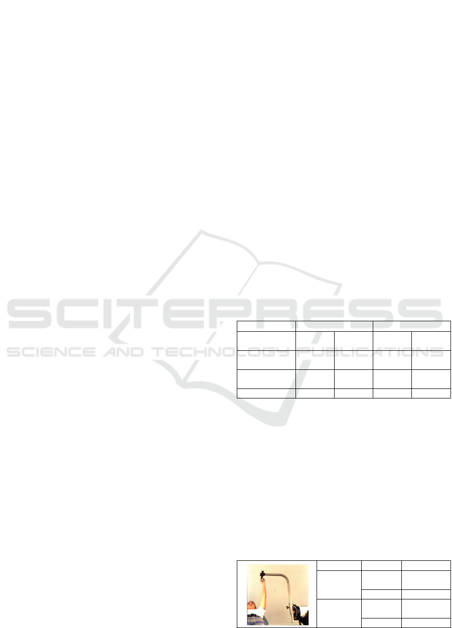
In order to analyse biomechanically the Gleno-
humeral joint, two isokinetic strength tests are
performed on a patient with Shoulder injury, at
BodyTech Sport Medicine. The tests are related to
movements of flexion and extension, and external
and internal rotation. Because we want to make a
preliminary analysis of the shoulder muscle response
in terms of strength; two tests of movements were
performed to measure the concentric forces. (Tables
2 and 3)
Table 2: Isokinetic force evaluation report. Flexion and
extension shoulder (supine).
Speed Force Repetitions
60/60
degrees/
seconds
Sub
Maximum
5
Maximum 5
180/180
degrees/
seconds
Sub
Maximum
4
Maximum 15
ICINCO 2018 - 15th International Conference on Informatics in Control, Automation and Robotics
488
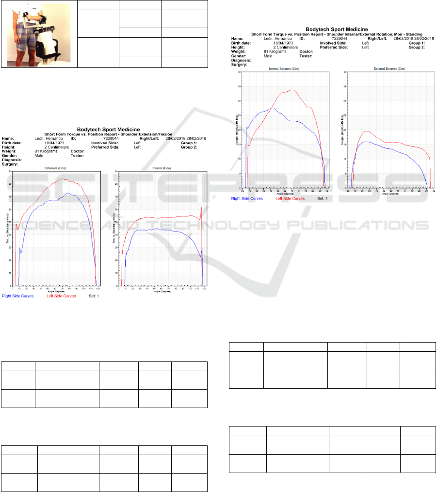
The results obtained are showing in figure 1 and
2 as follow: Curves of ratio of angles (degrees) and
torque (Newton by meters) for left and right
extremity. Tabulation of evaluation parameters for
left and right limbs in extension and flexion move-
ment, internal and external rotation: peak torque,
total work done, range of movement, deficits.
Table 3: Isokinetic stress evaluation report. Internal and
external shoulder (standing) rotation.
Speed Force Repetitions
60/60
degrees/
seconds
Sub
Maximum
5
Maximum 5
180/180
degrees/
seconds
Sub
Maximum
4
Maximum 15
Bilateral evaluation of extensors and flexors in
bilateral shoulder joints (supine) was performed on
Humac Norm Isokinetic dynamometer equipment,
complete range of motion is showing in figure 1.
Figure 1: Graphic of torque vs position shoulder
extension/flexion.
Table 4: Results evaluation of flexo test-shoulder
extension in speed of 60°/sec.
Speed Muscular Group Right Left Deficit
60°/sec
Concentric
Extenders
73 N/m 84 N/m 13%
60°/sec
Flexors
Concentric
45 N/m 65 N/m 31%
Table 5: Results flexo test-shoulder extension in speed of
180°/sec.
Speed Muscular Group Right Left Deficit
180°/sec
Concentric
Extenders
45 N/m 52 N/m 18%
180°/sec
Flexors
Concentric
35 N/m 65 N/m 50%
The results in the isokinetic evaluation,
maximum torque and total work of shoulder flexors-
extensors are identified in concentric contractions
(60, 180 degrees). Concentric isokinetic evaluation
was performed, given the following results. (Tables
4 and 5).
The second test was performing in bilateral
assessment of internal and external rotation in
bilateral shoulder joints (standing °) was performed
on Humac Norm isokinetic dynamometer
equipment, complete range of motion is showing in
figure 2.
Figure 2: Graphic or torque vs position shoulder
internal/external rotation.
In the isokinetic evaluation, maximum torque
and total work of shoulder flexors-extensors are
identified in concentric contractions (60, 180
degrees). Concentric isokinetic evaluation was
performed, given the following results. (Tables 6
and 7)
Table 6: Results of evaluation in test of internal and
external rotation of shoulder in speed of 60°/sec.
Speed Muscular Group Right Left Deficit
60°/sec
Concentric
Internal Rotation
27 N/m 34 N/m 20%
60°/sec
External rotation
Concentric
16 N/m 19 N/m 14%
Table 7: Results of evaluation in test of internal and
external rotation of shoulder in speed of 180°/sec.
Speed Muscular Group Right Left Deficit
180°/sec
Concentric
Internal Rotation
19 N/m 23 N/m 18%
180°/sec
External rotation
Concentric
8 N/m 11 N/m 25%
Improving the Joint Mobility of Acute Rotator Cuff Injury by Portable Rehabilitation Device
489
3 PROTOTYPE CONCEPTS AND
REQUIREMENTS
The design of the prototype to achieve shoulder
rehabilitation, should consider the following
requirements:
The first requirement corresponds to the way in
which the prototype adapts to the anatomical
variations of people with an age range of 49 to 60
years, starting at 95% of the percentiles, it is
possible to determine the average of the magnitudes
of each segment articulate, in order to obtain an
adjustable prototype for people who are within that
age range.
The second requirement is based on the fact that
the design must be ergonomic in order to allow its
portability and comfort at the moment of the
execution of the therapies.
The third requirement refers to the affordability
of the prototype since its low robustness decreases
the acquisition value, as well as decreases in costs,
which leads to the displacement of people to
healthcare entities by a therapy, since the proposal
goes focused on a type of independent therapy
developed in the home.
The fourth requirement is based on the
appropriate selection of actuators, whose function is
to mobilize the arm and forearm in 4 different types
of movements: flexion, extension, internal and
external rotation according to the degrees of
functionality of the patient. The movement is
continuously passive, since the high torque is
inversely proportional to the speed of the actuator.
The fifth requirement relates the benefits
provided by the prototype in terms of the execution
of therapies to improve the joint mobility of rotator
cuff injury and the investment that is made.
4 PROTOTYPE DESIGN
The methodology developed for the prototype
design starts from the population delimitation to
which it is addressed. This is how the dimensions of
this, are based on the average of Latin American
percentiles of men and women from 49 to 59 years,
based on the prevalence of injury in women for their
fourth decade of life and in men from the fifth.
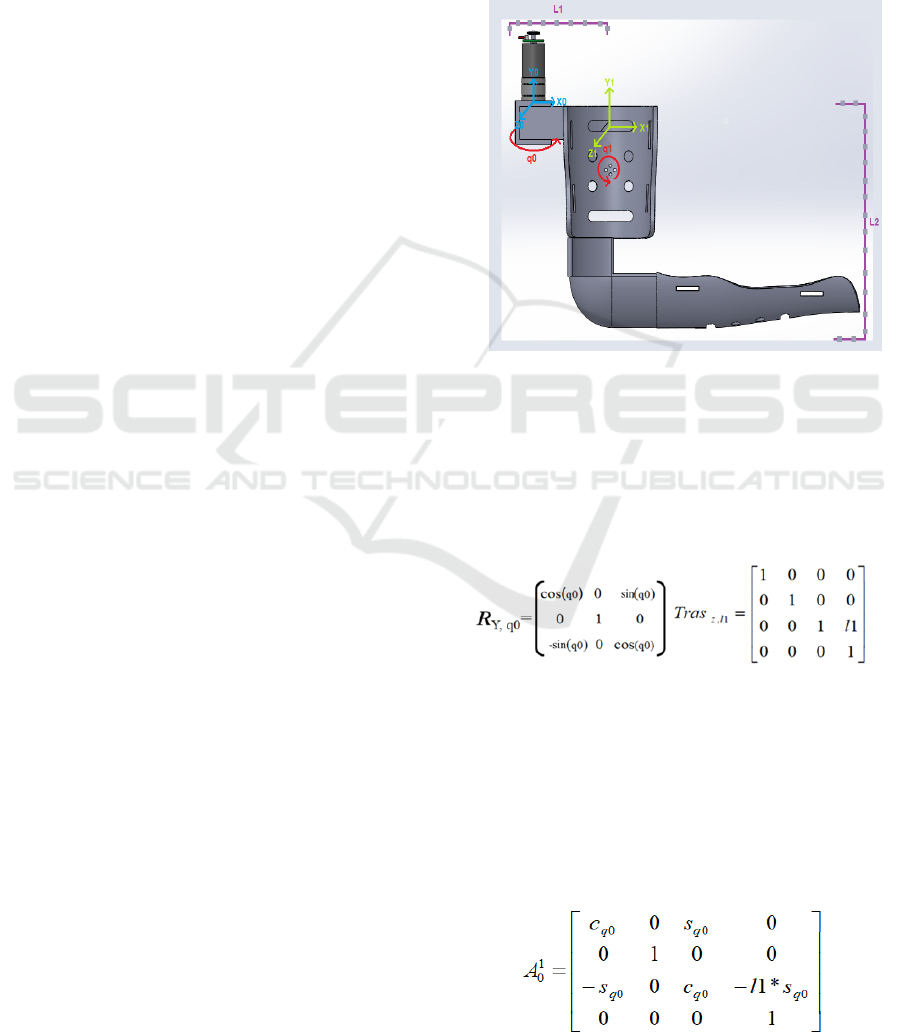
Based in the biomechanical evaluation and the
mentioned requirements a concept prototype
showing in figure 3 is designed under the operation
of a portable system driven by two gear-motors. The
kinematic and dynamic analyses are based on two of
the movements adapted by the articulation: flexion /
extension, external / internal rotation which activate
two degrees of freedom respective to the movements
of flexion and extension, and internal and external
rotation. The prototype consists of two supports for
the arm and the forearm, which will maintain the
extremity in the ranges of joint movements, required
performing the different rehabilitation exercises.
(Nef, 2011; Kim, 2017; Hunt, 2013).
Figure 3: Design of shoulder rehabilitation robot first
joint.
4.1 Kinematic Design
The kinematic system was obtained from a reference
axis of the shoulder, which was proposed for the
design of the system in the arm. (figure 3)
(1)
The rotation matrix RY, q0 gives the projection
of the coordinates in two coordinate systems. The
equation 1 is the first rotation matrix it is evident
that the system rotates on the Y axis and the
articulation that rotates on this axis is the one called
q0. In the translation matrix Tras z, l1 we can see
which link is transferred for the first system and on
which axis the movement is observed. In this case,
link 1 moves on the z axis.
(2)
ICINCO 2018 - 15th International Conference on Informatics in Control, Automation and Robotics
490
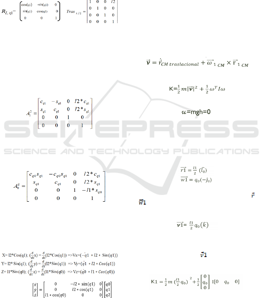
The equation 2 is the homogenous
transformation matrix A01, we can see the
projection of system 0 in system 1 and we can see
the sum or product point between the matrices of
rotation and translation. The breasts and cosines that
are evident in the rotation matrix, are the projections
of the vectors in both x and y.
(3)
The rotation matrix RZ, q1 gives the projection
of the coordinates in two coordinate systems. In the
first rotation matrix it is evident that the system
rotates on the Z axis and the articulation that rotates
on this axis is the one called q1. In the translation
matrix Tras
x,l2
you can see which link is transferred
to the second system and on which axis the
movement is observed. In this case, link 2 moves on
the x-axis.
(4)
In the homogeneous transformation matrix A12,
we can see the projection of system 1 in system 2
and we can see the sum or product point between the
matrices of rotation and translation.
(5)
After obtaining the homogeneous transformation
matrix of the system q1 and q0, multiplication or
cross product of both homogeneous matrices is
performed to find the position of the end terminal,
with respect to the whole system.
(6)
The Jacobian matrix is used to determine the
speed of movement in each of the axes, which is
solved by the partial derivative of the last column of
the total homogeneous transformation matrix, which
represent each of the axes in descending order.
The dynamic system develops from the
description of the movement together with the forces
involved in the system. To determine the kinetic
energy, it was necessary to calculate the velocity
vector, which is composed of the sum between the
vector derivative of r
CM
centre of translational mass
plus the angle of rotation, by the cross product of the
vector r
CM
of centre of mass.
Once the velocity vector is found, the kinetic
energy and the potential energy are found.
(7)
(8)
(9)
The vector r
1
is composed of a medium of link 1
in the direction i0, while the vector w1 is given by
the rotation q0 in the opposite direction to the
movement -j
0
, the vector v
1
is given by a means of
link1 by the rotation q0 in the address k.
(10)
After determining each of the variables (
1 y
), we find the velocity, which gives us as a result,
since the derivative of R1 with respect to q0 is 0.
(11)
Once the velocity is found, the value is replaced
in the kinetic energy equation, where WT is the
transpose of the vector
and I is a matrix of
inertia.
(12)
In addition to this, the potential energy is found
where m1 corresponds to the mass of the first link
Improving the Joint Mobility of Acute Rotator Cuff Injury by Portable Rehabilitation Device
491
and g to the value of gravity.
(13)
For the second joint articulation of the system
showing in figure 3, the same methodology was
carried out, with which the energies were obtained in
the first articulation. With the difference that for the
second system the articulation had to be taken into
account to find the value of the variable
.
4.2 Design and Operation
Characteristics
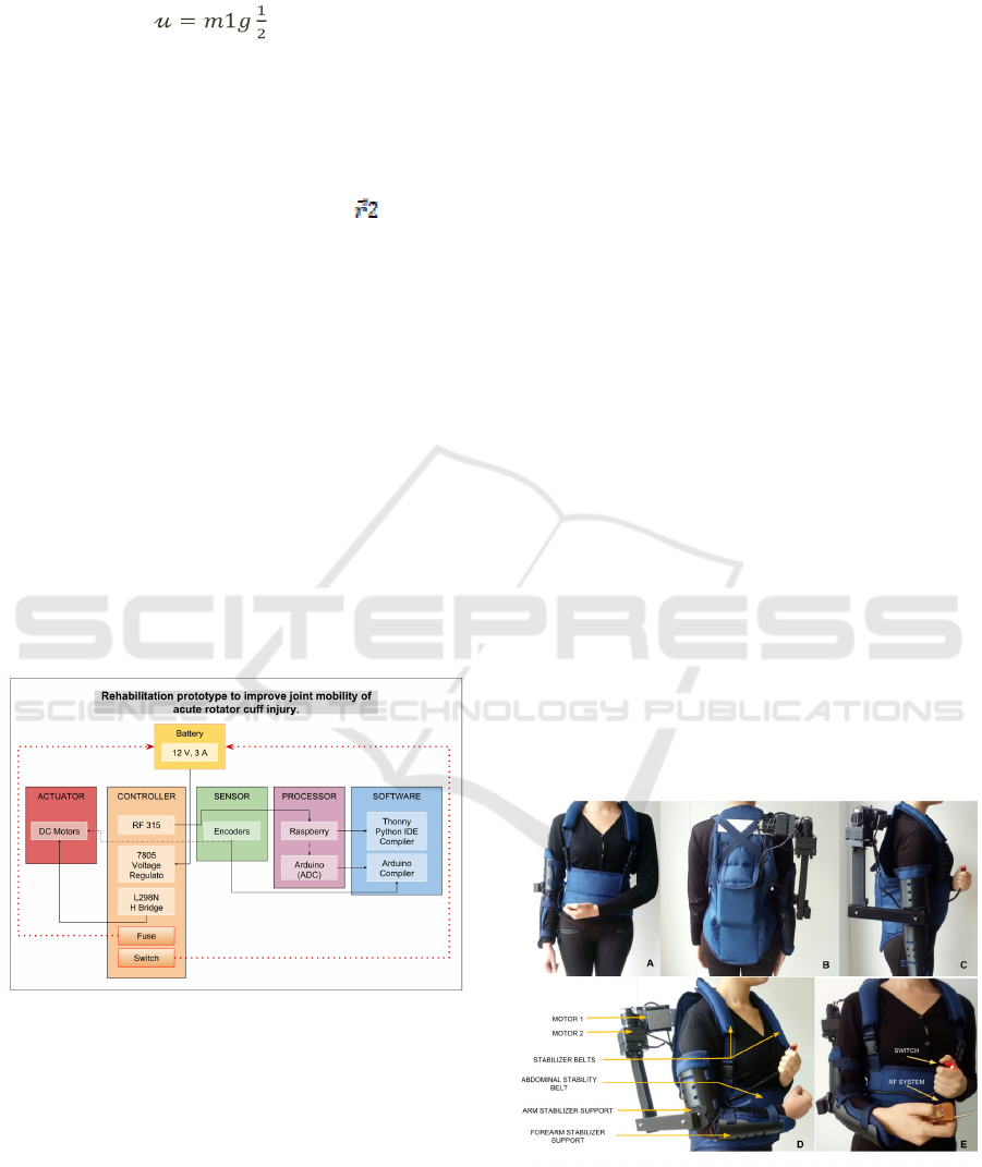
As shown in Figure 4, the operation of this prototype
starts from a 12V power supply that ensures its
portability, which supplies the L298N (Bridge H)
that gives the control of rotation of two motors,
which act as actuators of the system. Because it is
necessary to determine the ranges of extension /
flexion movement, external / internal rotation, the
angles are sensed by using two encoders, one for
each motor. The control of the motors, is given by
means of a processor Raspberry PI 3B, controlled by
the software compiler Thonny Python IDE. A 7805
voltage regulator is implemented because the
software voltage should not exceed 5V.
Figure 4: Schematic diagram of control architecture.
The prototype involves direct contact with
patients to be scaled at an industrial level, therefore,
and thinking about the safety of the patient, requires
a fuse that has the function of dampening the high
currents that the circuit can reach; Added to this, it
has an emergency button (Switch), which will be
activated by the patient in case of alarm, causing the
entire system to shut down completely and stop its
operation. The movements will be controlled and
executed by an emitter-receiver radio frequency
system, which will carry with it the pre-established
therapy routines.
4.3 System Prototype
Once the requirements are known, this prototype is
designed to perform specific therapies by means of
an emitter receiver control system, which the patient
will have to resort to perform a specific task that
starts from the movement of flexion, extension,
internal and external rotation within the angles of
functionality of the joint. The prototype consists of
two stabilizing components showing in figure 5.
The first component consists of a piece that
supports the forearm and the arm, and has an
elongation fabric that allows the user to have
mobility in the elbow (A). The second component is
an abdominal stabilizer, which brings stability to the
back, and so that the therapy is exercised upright,
without complications to the spine, in addition, the
trellis has two shoulder straps or stabilizers that they
allow the weight of the actuators to dissipate through
them, in addition, the trellis has a pocket that groups
the electronic components, in order to make it easy
to access adjustments or even remove the battery to
charge it (B). The figure 6 is showing the actuator
that exerts the movement of flexion - extension, has
a support that is connected directly to the trellis and
a connector that intertwines the other actuator,
which performs the external and internal rotation
movement and is connected to the forearm support
by a piece which lengthens as the flexion movement
(C) is performed.
Figure 5: Prototype of shoulder rehabilitation robot
system. (A) front and (B)posterior sagittal axis of the
device placed on patient. (C) Right view. (D) Stabilizing
components. (E) Control accessories.
ICINCO 2018 - 15th International Conference on Informatics in Control, Automation and Robotics
492
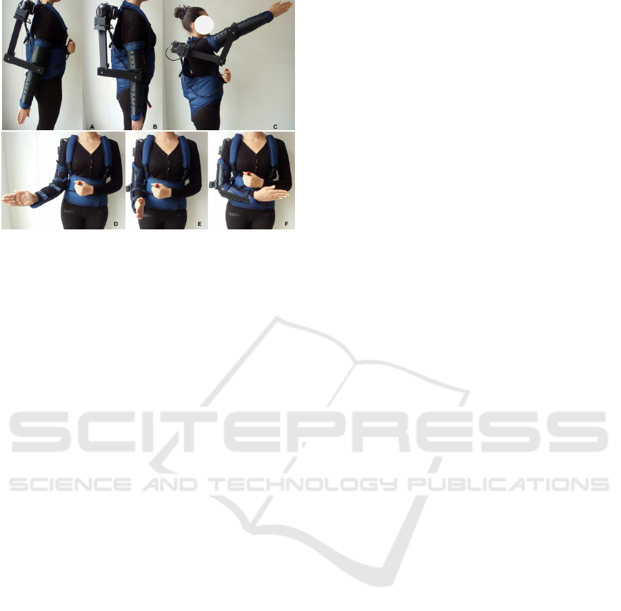
Figure 6: Prototype of shoulder rehabilitation robot
system. Side view of the device in movement of extension
to 45 ° (A), position of anatomical zero (B) and movement
of flexion to 120 ° (C) of Shoulder. Front view of the
device in movement of external rotation at 50 ° (A),
anatomical zero position in 90 ° elbow flexion (B) and
internal rotation movement at 70 ° (C) of Shoulder.
4.4 Control System
The coupling that has the encoders in the motors
allows us to know the position angle in which the
stabilizing support is, this is a main part in the
control system of the prototype, however, the
therapy protocol is organized by time and execution
angles, which is programmed through the raspberry
microcontroller Pi 3B that has as operator the remote
control, which executes the specific tasks according
to the therapy that the user wishes to perform.
The kinematic and dynamic conceptual system
developed are based on two of the movements
adapted by the articulation: flexion / extension,
external / internal rotation, which represent a need
for assistance with the aim of achieving efficient
rehabilitation, following patterns of movements that
although they start of international therapy process,
allows the proper monitoring of them. From the
kinematics, the velocities and total accelerations of
the system are obtained from the position of the
terminal end of the forearm.
5 DISCUSSION RESULT AND
CONCLUSIONS
The rupture of the components of the rotator cuff is
one of the main causes of musculoskeletal pain as
well as disability. Rehabilitation is understood as the
set of methods that aims to recover a function or
activity that has been diminished or lost due to
illness or trauma; When talking about robotic
rehabilitation, various approaches are found such as
robotics for mobility, for personal rehabilitation,
developments of prostheses and orthoses, of social
assistance and as observed in the present
development, for upper and lower extremities. It
should be noted that all these approaches are based
on the use of conventional therapies at the
beginning, that over time and the influence of
alternative mechanisms, engineering concepts are
integrated for medical purposes. The new
technologies point to the use of soft materials, which
improve the ergonomics of the rehabilitation system,
within the exponents of bio-robotics is Active Soft
Orthotic System, the main reference for the
execution of this device.
The difficulty in the application of technologies
for the rehabilitation and joint mobility of the rotator
cuff was born in two main causes, technological and
medical. The technological causes, because the
current robotic advances are complex and based on
kinematic chains of rigid links that lead to little
ergonomics, hand in hand with the implements used
in the maintenance of the same that represent high
costs, increasing prices for institutions providers and
providers of related services. The medical causes, in
addition to being a degenerative process that triggers
abrupt tensions on the supraspinatus tendon or
dislocations, which lead to the increase of
musculoskeletal diseases, are also related to the
stress generated by repetitive work, reflected in
direct pathologies to the shoulder and pain joint,
increasing injuries in upper limbs.
The analysis of the kinematic system of the
shoulder allowed differentiating the movements
produced by the five joints (the acromioclavicular
joint, the sternoclavicular joint, the scapula-thoracic
joint and the gleno-humeral joint) that make up the
shoulder, the passive limitations that offer stability
to the joint complex, Static stabilizing elements such
as anatomical differences in joint surfaces and
ligaments. On the other hand, dynamic analysis
states that the main stabilizers of the shoulder are the
muscles that belong to the gleno-humeral joint.
Likewise, we identified the two types of forces
exerted by the shoulder (compression and shearing),
and the anatomical rotations exerted by the gleno-
humeral joint such as: adduction / abduction,
internal / external rotation, flexion / extension by
Euler angles.
The tests performed on the isokinetic
dynamometer Humac Norm allowed to analyse the
complete biomechanical ranges of movement by
Improving the Joint Mobility of Acute Rotator Cuff Injury by Portable Rehabilitation Device
493

means of the bilateral evaluation of flexors and
extensors of the shoulder, as well as internal and
external rotators of the joint. Isokinetic contractions
refer to maximum contractions of the muscle groups
involved with constant velocities along the radius of
joint movement, which allowed during the design of
operation of the device, to establish optimal ranges
of speed according to pre-established requirements,
together with the design of sets in terms of
repetitions and angular variation, discriminating
each type of movement. The complete protocol was
followed for the tests mentioned above in the
Humac, accompanied by medical personnel trained
in facilities of the BodyTech Sport Medicine Center.
The patient chosen for the execution of the test is
within the age range related to the prevalence of the
appearance of the pathology associated with rotator
cuffs, that is, between 40 and 50 years of age.
The isokinetic strength assessment reports,
provide relationship curves between the right and
left sides of the shoulder for each movement, and
quantification of evaluation parameters such as:
peak torque or maximum force moment, which
indicates the maximum capacity of the muscle to
generate strength and comparison of agonist and
antagonist muscles determined in the five initial
repetitions for each movement; Total work done,
defined as the torque product per distance traveled,
that is, the areas under the presented curves that
indicate the capacity of the subject to produce torque
and the estimation of muscle resistance indexes; and
the Power that determines the torque produced
depending on an angular distance traveled in a time
of execution of movement, which expresses the
relationship between the value of work produced in
the time required to complete the exercise.
Based on the quantitative study of the
anthropometry of the working population in
Colombia, with an age range of 20-59 years and a
percentile of 95% which determines that below that
measurement value the population is found, the
measures were determined necessary to build the
device, however, because the anthropometric tables
are separated by sex, an average of each
measurement was made between man and woman to
have a value per measurement, so that the device
was not exclusive regardless of the gender.
Once the prototype was built according to the
anthropometric measurements, it was possible to
demonstrate that it is an ergonomic prototype, since
the actuators adapt to the anatomical characteristics
of the Glenohumeral joint, because the insertions of
the actuators are similar to the anatomical insert that
exists between the humerus and the omoplate.
However, the joint module constructed generates an
additional weight because the plate that holds it has
a smaller size compared to the size of the module,
which indicates that an additional piece must be
created that keeps the module rigid on the trellis, this
to reduce the additional weight generated by the lack
of support.
ACKNOWLEDGEMENTS
The authors wish to thank César Rocha Libreros,
orthopaedic surgeon and reconstructive and knee
arthroscopy surgeon of Fundación Cardio Infantil,
for the clinical vision he gave us on the subject of
rehabilitation.
REFERENCES
Armeo® Spring-Hocoma, [Online accessed: 18/3/2018];
https://www.hocoma.com/solutions/armeo-spring
Ciarán T. O’Neill, Nathan S. Phipps, Leonardo Cappello,
Sabrina Paganoni and Conor J. Walsh; 2017, A Soft
Wearable Robot for the Shoulder: Design,
Characterization, and Preliminary Testing; IEEE Int
Conf Rehabil Robot.
Domien Gijbels, Ilse Lamers, Lore Kerkhofs, Geert
Alders, Els Knippenberg, Peter Feys; The Armeo
Spring as training tool to improve upper limb
functionality in multiple sclerosis: a pilot study;
Journal of Neuro Engineering and Rehabilitation
2011, 8:5.
Galiana Ignacio, Hammond Frank L., Howe Robert D. and
Popovic Marko B. 2012; Wearable Soft Robotic
Device for Post-Stroke Shoulder Rehabilitation:
Identifying Misalignments; IEEE/RSJ International
Conference on Intelligent Robots and Systems October
7-12, 2012. Vilamoura, Algarve, Portugal.
Gonçalves Rodrigo, Antunes Cerejo; 2016, A Robotic
System for Musculoskeletal Rehabilitation of the
Shoulder; Biomedical Engineering - Universidade de
Lisboa.
InMotion ARM™ Interactive Therapy System - Bionik
Labs; http://bionikusa.com/healthcarereform/upper-
extremity-rehabilitiation/inmotion2-arm/. [Online
accessed: 18/03/2018].
Habets Bas, Staal J. Bart, Tijssen Marsha and Cingel
Robert van; 2018, Intrarater reliability of the Humac
NORM isokinetic dynamometer for strength
measurements of the knee and shoulder muscles;
Res Notes (2018) 11:15.
Hunt Justin, Lee Hyunglae, Artemiadis Panagiotis; A
Novel Shoulder Exoskeleton Robot Using Parallel
Actuation and a Passive Slip Interface; Journal of
Mechanisms and Robotics; 2017.
James Cannan and Huosheng Hu, 2012. Upper Body
ICINCO 2018 - 15th International Conference on Informatics in Control, Automation and Robotics
494

Rehabilitation A Survey; University of Essex,
Colchester CO4 3SQ, U.K; ISSN 1744-8050.
Kesner, S., Jentof, L., Hammond III, F., Howe, R., &
Popovic, M.; 2011, Design Considerations for an
Active Soft Orthotic System for Shoulder
Rehabilitation; 33rd Annual International Conference
of the IEEE Engineering in Medicine and Biology
Society (EMBC).
Kim Bongsu and Deshpande Ashish D; 2017, An upper-
body rehabilitation exoskeleton Harmony with an
anatomical shoulder mechanism: Design, modeling,
control, and performance evaluation; The International
Journal of Robotics Research; 1–22.
Nunes W., Rodriguez L. and Oliveira L.; 2011, Cable
based parallel manipulator for rehabilitation of
shoulder and elbow movements; IEEE Int Conf
Rehabil Robot.
Nef Tobias, Guidali Marco and Riener Robert; 2009,
ARMin III – arm therapy exoskeleton with an
ergonomic shoulder actuation; Applied Bionics and
Biomechanics Vol. 6, No. 2, June, 127–142.
Orth T., Paré J., Froehlich J. E.; 2017, Current concepts on
the genetic factors in rotator cuff pathology and future
implications for sports physical therapists.
International Journal of Sports Physical Therapy.
2017;12 (2):273-285.
Sicuri Chiara, Porcellini Giuseppe, Merolla Giovanni;
2014, Robotics in shoulder rehabilitation; Muscles,
Ligaments and Tendons Journal 2014; 4 (2): 207-213.
Improving the Joint Mobility of Acute Rotator Cuff Injury by Portable Rehabilitation Device
495
