
Constant Curvature Kinematic Model Analysis and Experimental
Validation for Tendon Driven Continuum Manipulators
S. Mosqueda
1
, Y. Moncada
1
, C. Murrugarra
1
and H. Le
´
on-Rodriguez
1,2
1
Electronic Engineering Program, El Bosque University, Bogota, Colombia
2
Bioengineering Program, El Bosque University, Bogota, Colombia
Keywords:
Robotic, Kinematic, Continuum, Workspace, Tracking, End Effector, Mathematical Model.
Abstract:
In this paper an analysis is done to the current kinematic model for continuum robot, with the goal of deter-
mining the accuracy of the experimental validation of the constant curvature kinematic model to establish a
relation between the mathematical model and continuum robot, and its feasibility of applying for any type of
continuum structure, measuring the end effector planar trajectory based on the displacement of passive cables
located along the structure. To test the kinematic model, a prototype of continuous robot composed of 1 seg-
ment with 7 sections, controlled by 3 cables, per section was fabricated, we also propose a modular segment
(link) with free joints, the modularity allows to extend the length of the segment and also allows to add seg-
ments and connect in the form of serial chain and describe the radius of concave and/or convex curvature and
allow the robot manipulator to follow different trajectories and displacements in their workspace. The kinema-
tic model of constant curvature used in continuous robots with minimal positioning errors was implemented
and tested.
1 INTRODUCTION
The robotics field is ever-growing and developing, al-
ways looking for ways to provide solutions for speci-
fic needs; in the beginning, research was mainly focu-
sed automated manipulators that could take the place
of humans in dangerous work environments or ma-
nufacturing processes, especially in those were effi-
ciency meant executing a task over and over, always
in the same time. Industrial robots have traditionally
consisted of a serial like to connect joints directly ac-
tuated (Pires, 2007), although these types of robots
have been proved to be useful in many scenarios, they
have obvious drawbacks in more constricted spaces
due to the lack of compliance generated by the low
level of flexibility and degrees of freedom (D.O.F.),
and in real-world scenarios and situations that are not
pre-choreographed, it is generally not feasible to use
the rigid link manipulator.
Many of these problems have been resolved
through biologically inspired designs, which aim to
copy the movement properties and adaptability of cer-
tain animal extremities such as octopus, or squid ten-
tacles (Laschi et al., 2012), (McMahan et al., 2006),
elephant trunks (Tiefeng et al., 2015) and snake-like
structures (Crespi et al., 2005). This type of me-
chanism known as a continuum or hyper-redundant
robots differs from traditional manipulators in the
sense that they are capable of possessing a high range
of flexibility and more degrees of freedom enabling
them to traverse precisely through almost any ”space”
and around many obstacles. Hence, they are conside-
red to be ideal for probing cramped and hazardous in-
dustrial environments, as they can be used to inspect
nuclear reactors (Ma et al., 1994), as well as confi-
ned spaces (Liu et al., 2016), to search and rescue in
disaster situation (Meng et al., 2013), and in recent
years, they have gained wide interest from the medi-
cal field (Burgner-Kahrs et al., 2015), specifically, in
conducting Minimal invasive surgery (MIS) (Burgner
et al., 2014).
This type of robots can be classified by a defi-
ning feature, which is a continuously curving back-
bone or core, its shape can be modified with diverse
types of actuated mechanism, tendon mechanism (Li
et al., 2016) or pneumatic mechanism (Mahl et al.,
2014); this backbone, even though it is known as con-
tinuous as it can be segmented, compromised of a
series of rigid-links, which together give the appea-
rance of a continuous structure. One of the best exam-
ples of this can be seen in a development done by the
British company OC robotics (Robotics OC, 2016).
Mosqueda, S., Moncada, Y., Murrugarra, C. and León-Rodriguez, H.
Constant Curvature Kinematic Model Analysis and Experimental Validation for Tendon Driven Continuum Manipulators.
DOI: 10.5220/0006913502110218
In Proceedings of the 15th International Conference on Informatics in Control, Automation and Robotics (ICINCO 2018) - Volume 2, pages 211-218
ISBN: 978-989-758-321-6
Copyright © 2018 by SCITEPRESS – Science and Technology Publications, Lda. All rights reserved
211

Most continuum robots can also be known as under-
actuated since they have fewer actuators than DOFs.
these under-actuated systems allow for a significant
simplification of the control system, with the disad-
vantage that some workspace is lost due to the reduce
dexterity. With this in mind, we can further classify
these robots by their type of actuation and structure,
in three main categories, Tendon-driven, concentric
tube and locally actuated(Walker, 2013), also known
in the literature as tendon-driven continuum manipu-
lators (TCM), tendon-driven serpentine manipulators
(TSM) and concentric tube manipulators (CTM)(Li
et al., 2017).
With the goal of obtaining a reliable kinematic
model, capable of accurately describing the behavior
of any continuum robot first we have to review what
developments have been made so far, starting from the
proposal of clothoid curves for mimicking a snake’s
locomotion (Hirose, 1995), followed by the work of
Chirikjian and Burdick that extended on this approach
of fitting the hyper-redundant robot to analytical desi-
rable mathematical curves by establishing them as the
product of a Bessel function with sines and cosines
(Chirikjian and Burdick, 1995b), furthermore, they
described the behavior of the constant curving struc-
ture using the Frenet-Serret Frames equations (Chi-
rikjian and Burdick, 1995a). Subsequently, the work
of Walker (Jones and Walker, 2006), Zheng, Webster
and Jones (Webster and Jones, 2010) allowed for the
integration of these models, with the D-H parameters
(Hannan and Walker, 2003), the integral representa-
tion and a product of exponentials (POE)(Li et al.,
2017), to finally derive the constant-curvature kine-
matic model, which is one of the most well-known
and used for modeling continuum robots.
In this work we aim to do an experimental vali-
dation of the constant-curvature kinematic model to
establish a relation between the mathematical model
and continuum robot, measuring the end effector pla-
nar trajectory based on the displacement of passive
cables located along the structure, with the purpose of
estimating the resulting shape of the planar trajectory,
a video processing software was used.
This paper presents the Introduction as the first
section, then a formal description of the Mathematical
model, followed by the description of the Experi-
mental Setup explaining the technical characteristics
of construction of the continuous robot, motion, and
measurements, we continue with the Results and
finally the Conclusions.
2 MATHEMATICAL MODEL
This section defines the kinematic model that will be
applied to describe the manipulator shape and end-
effector position. As mentioned in the introduction,
a robust kinematic model based on constant curva-
ture, seems to be the best option for describing the
movements of a continuous structure.
According to classical robotics, modeling of an ar-
ticulated system, consist of determining the position
and orientation of the end effector, regarding a system
of reference coordinates at the base of it, this can be
achieved by defining a robot as a set of rigid elements
or link joints, however, this method is not applicable
to a system that has more degrees of freedom than
those needed to carry out a basic task, as is the case
with continuous robots.
This kinematic model, developed (Jones et al.,
2006) and (Chirikjian and Burdick, 1995a), uses a se-
ries of substitutions on the Denavit-Hartenberg (D-H)
transformation matrix, in order to obtain a model that
defines a more approximate behavior, where a stan-
dard homogeneous transformation matrix A(θ, d) is
used to describe a series of independent translations
and rotations. The latter requires a different mathe-
matical analysis, in which a series of substitutions are
made on the D-H transformation matrix, in order to
obtain a model that relates a more approximate beha-
vior. The conventional notation involving a homoge-
neous matrix is yielded by A(θ, d), where: θ repre-
sents the independent rotations of the joints and d the
translations. However, for continuous robots, perfor-
ming this analysis involves a homogeneous matrix for
each section that makes up a segment, so authors such
as Ian D. Walker, which associates the shape of the
robot with a curve in space by the middle of the Fre-
net Serret equations (DHB, 2013), one can establish
an equivalent to rotations and translations. Thus, the
A =
cos
2
(φ)[cos(ks −1)] + 1 sin(φ)cos(φ)[cos(ks −1)] −cos(φ)sin(ks)
cos(φ)[cos(ks−1)]
k
sin(φ)cos(φ)[cos(ks −1)] cos
2
(φ)[cos(ks −1)] + cos(ks) −sin(φ)sin(ks)
sin(φ)[cos(ks−1)]
k
cos(φ)sin(ks) sin(φ)sin(ks) cos(ks)
sin(ks)
k
0 0 0 1
(1)
ICINCO 2018 - 15th International Conference on Informatics in Control, Automation and Robotics
212
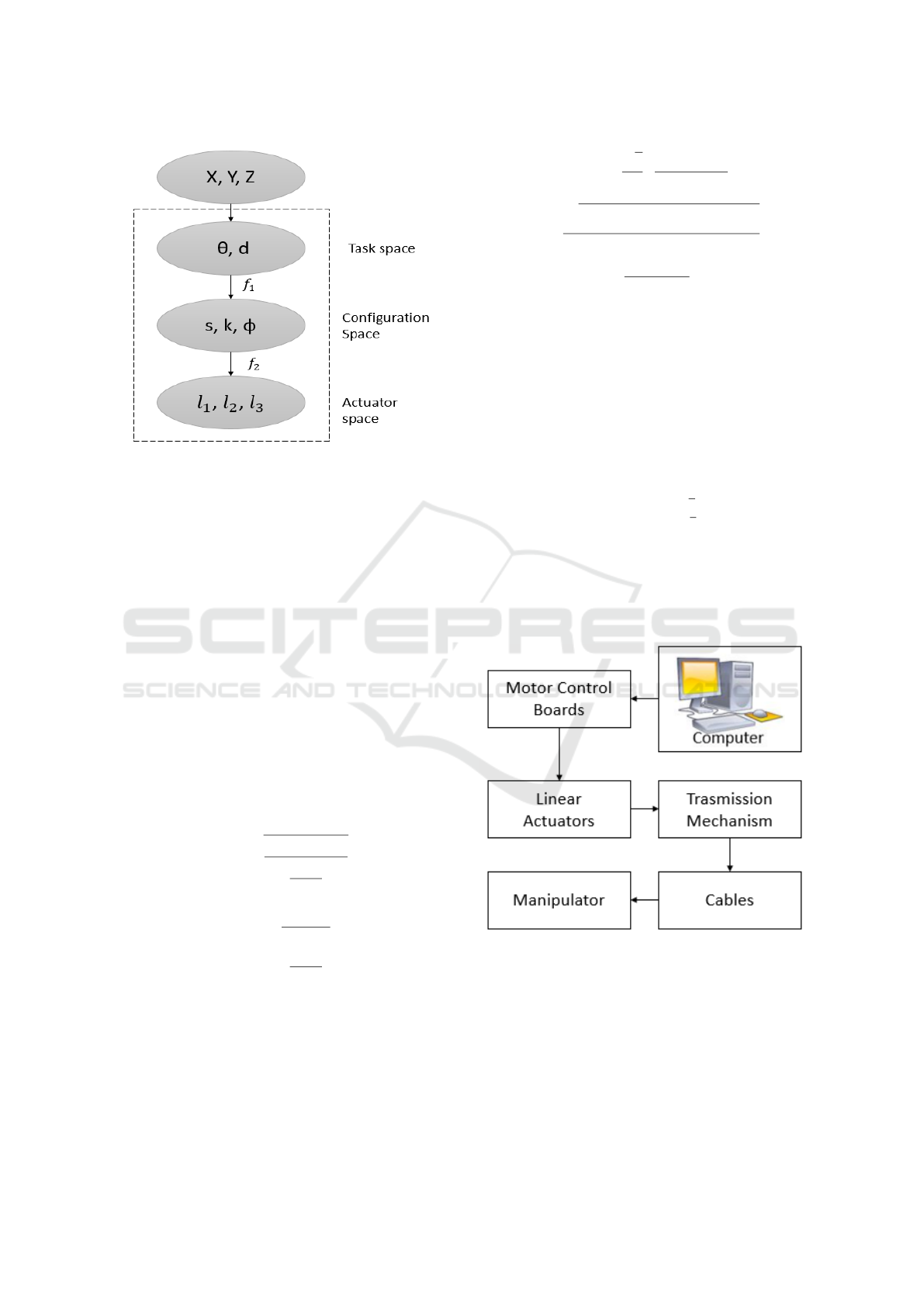
Figure 1: The space transformations between the D-H para-
meters and s, k , φ, l
1
, l
2
and l
3
.
first step to obtaining a reliable mathematic model, is
to establish a relationship between the D-H parame-
ters θ, and the trunk parameters s, k, φ, and from this,
obtaining a more approximate approach to the conti-
nuum robot movements in terms of the cable length
(Jones and Walker, 2006), (Webster and Jones, 2010).
The space transformations between the D-H parame-
ters and s, k, φ and l
i
, as shown in Figure.1.
According to the coordinate system and the geo-
metric relationship with the arc parameters, the ho-
mogeneous matrix of the n segment can be calculated
as Eq.1, where the matrix of transformation A, allows
us to know the position and orientation to perform an
analysis of the bending of the continuum robot of the
end effector and its workspace (3D). In Eq.2, the
space position of the end effector and Eq.3, get the
bending performance on 2D with the matrix.
P
x
P
y
P
z
=
cos(φ)[cos(ks−1)]
k
sin(φ)[cos(ks−1)]
k
sin(ks)
k
(2)
P
x
P
y
P
z
=
cos(ks−1)
k
0
sin(ks)
k
(3)
Through equations Eq.4, Eq.5 and Eq.6, we can find
the position of the end effector in regard to the arc
parameters, these parameters can be controlled by ad-
justing the length of the tensor cables, therefore, its
necessary to derive the mapping from the linear actu-
ators length to the arc parameters.
φ = tan
−1
√
3
3
·
l
3
+ l
2
−2l
1
l
2
−l
3
!
(4)
k = 2
q
l
2
1
+ l
2
2
+ l
2
3
−l
1
l
2
−l
2
l
3
−l
1
l
3
d(l
1
+ l
2
+ l
3
)
(5)
s =
l
1
+ l
2
+ l
3
3
(6)
Finally, establish a connection to obtain the position
of the end effector in relation to the cable lengths, we
must know the following parameters from a section of
the manipulator; the length of one of its segments, the
curvature of the section (k), the angle at which the cur-
vature (φ) is found, the distance from the center of the
manipulator to the location of the cables (s), and the
number of segments in the manipulator section (n);
with these parameters we obtain the Eq.7.
l
1
l
2
l
3
=
s[1 −kd sin(φ)]
s
1 + kd sin
π
3
+ φ
s
1 −kd cos
π
6
+ φ
(7)
3 EXPERIMENTAL SETUP
The experimental platform for Continuum Robot Ma-
nipulator is shown in Figure.2.
Figure 2: The experimental platform for Continuum Robot
Manipulator.
The Continuum Robot Manipulator system was im-
plemented by:
1. Processing central by a computer.
2. Motor Control Boards using the three Phidget mo-
tor control (1065),
Constant Curvature Kinematic Model Analysis and Experimental Validation for Tendon Driven Continuum Manipulators
213
3. Linear Actuators and Transmission Mechanics by
three ECO-WORTHY: stroke length 150mm, ra-
ted at 5.7mm/s, 1500N pull and 1200N push force
with magnetic encoder.
4. Cables wire, stainless-steel (316), with 0.28m in
length and 3.00mm in diameter.
5. Manipulator one segment in PVC with 0.22m in
length and 0.08m in diameter, with seven sections,
free joints.
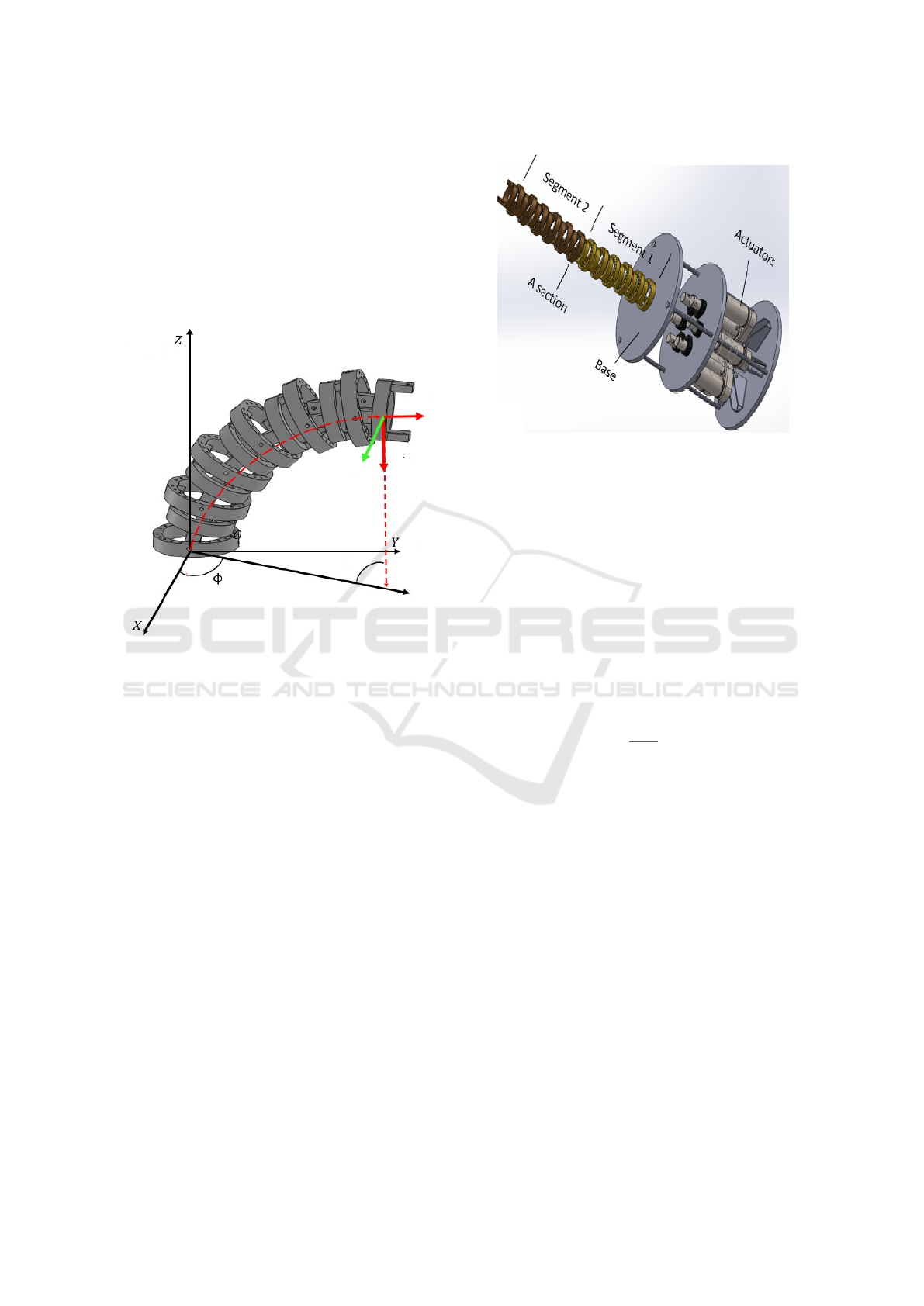
Figure 3: The Continuum Robot Manipulator composed of
1 segment, 6 sections and free joints between sections.
Figure.3, shows a computer rendering of the manipu-
lator prototype, composed of 1 segment, 7 sections
and free joints between sections. Figure.4, shows a
computer rendering of the robotic extended prototype,
where of the manipulator is composed of 2 segments,
14 sections, 6 cables (3 for each segment), and 6 li-
near actuators, one for each cable.
The kinematic model used to obtain the necessary
cable lengths to move the manipulator to a certain po-
sition was simulated with MATLAB, using the equa-
tions of the section 2. To start the experimental vali-
dation, first we chose a position in the X, Z plane, that
we wanted the end effector to be in, then, we procee-
ded to reposition the motors using the Motor Control
Boards until the lengths of the tension cables in the
experimental prototype were as close as possible to
the theoretical lengths, in order to compare the final
position of the actuator.
4 RESULTS
Figure.5, shows the evaluation of the mathematical
model for a continuum robot manipulator implemen-
Figure 4: Design of the Continuum Robot: composed of 2
segments, 14 sections, 6 cables (3 for each segment), and 6
linear actuators.
ted in this work, 1segment = 0.220m.
Figure.6, shows the continuum robot manipulator
(1 segment) implemented for an experimental posi-
tion obtained using the kinematic model and calculate
the medium squared error and find out how accurate
is the mathematical model, the position of the end-
effector was acquired using the Tracker video analysis
and modeling tool software.
To validate the mathematical model, a series of
experiments were performed, in these tests, the max
values of arc parameters were measured during plan-
ned movements of the manipulator with the following
conditions: φ = 0, s = constant value = 0.220m, and a
maximum value of k =
1
0.14m
, obtaining the magnitu-
des of the lengths of the cables with Eq.7.
Using the video Tracker software and bright co-
lored markers to get a better recognition of the robot
segments, 3 tests were run, in each one, the movement
values of X(m) y Z(m) was recorded. Different test
experiments were performed as the one on Figure.7,
under some values of calculated for l
1
, l
2
, l
3
, and Fi-
gure 8, shows one of the results of tracking the mo-
vements previously described, in this case, to be con-
sistent with the variables used, for this figure the “X”
axis is the “Z” axis corresponding to our nomencla-
ture.
From Table.1, through the measuring of the ca-
ble lengths, calculating the curvature of the end effec-
tor and comparing it to the theoretical model, where:
k
theo
is obtained by the mathematical model and k
exp
is the measure in the experimental setup implemen-
ted. To further evaluate the tracking performance of 3
tests, the Root Mean Square Error (RMSE) is used as
follows for each one of them.
ICINCO 2018 - 15th International Conference on Informatics in Control, Automation and Robotics
214
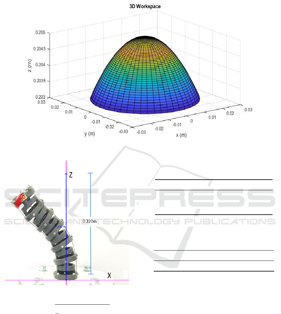
Figure 5: 3D Workspace defined by the mathematical model for Continuum Robot Manipulator with dimensions of the
manipulator whit length=0.220m.
Figure 6: Moving Robot positioning using Tracker soft-
ware.
RSME =
s
1
n
n
∑
i=1
(
k
Z
theo
−Z
exp
k
)
2
(8)
where n is a given time for taking samples, n is the
total number of samples in that given time, Z
theo
, is
the desired trajectory and Z
exp
, is the measured trajec-
tory. In the experiments javascript:void(0);conducted
we took n=82 samples during the period of 2.7 minu-
tes.
From Table2, we can see that the RMSE is well
within the normal and functional values and that this
error can very well be caused by mechanical imper-
fection in the prototype.
Table 1: Experimental Results: Calculating the curvature of
the end effector in the experimental setup and comparing it
to the theoretical model.
l
1
(m) l
2
(m) l
3
(m) k
theo
(m) k
exp
(m)
0.20 0.20 0.20 Ind Ind
0.20 0.24 0.16 0.14 0.13
0.20 0.22 0.14 0.20 0.18
Table 2: Experimental Results: Evaluate the tracking per-
formance using RMSE comparison by the desired trajec-
tory and measured trajectory in three tests and µ (mean or
arithmetic average) .
Test1 (m) Test2 (m) Test3 (m) µ
0.0156 0.0352 0.0016 0.0023
The results shown in Figure.9, illustrate the
tracking performance in terms of the RMSE of all the
experiments, their average and the calculated trajec-
tory. As we can see, the RMSE reaches to 0.015 m
(0.0153 m to 0.035 m) in the open-loop case, whereas
the RMSE decreases to only 0.05 m with the measu-
red trajectories average.
5 CONCLUSION
In this paper the mathematical model in the space
transformations between the D-H parameters and s,
k , φ, l
1
, l
2
and l
3
was implemented and tested the
constant curvature kinematic model currently used in
most continuum robot manipulators, and from the re-
Constant Curvature Kinematic Model Analysis and Experimental Validation for Tendon Driven Continuum Manipulators
215
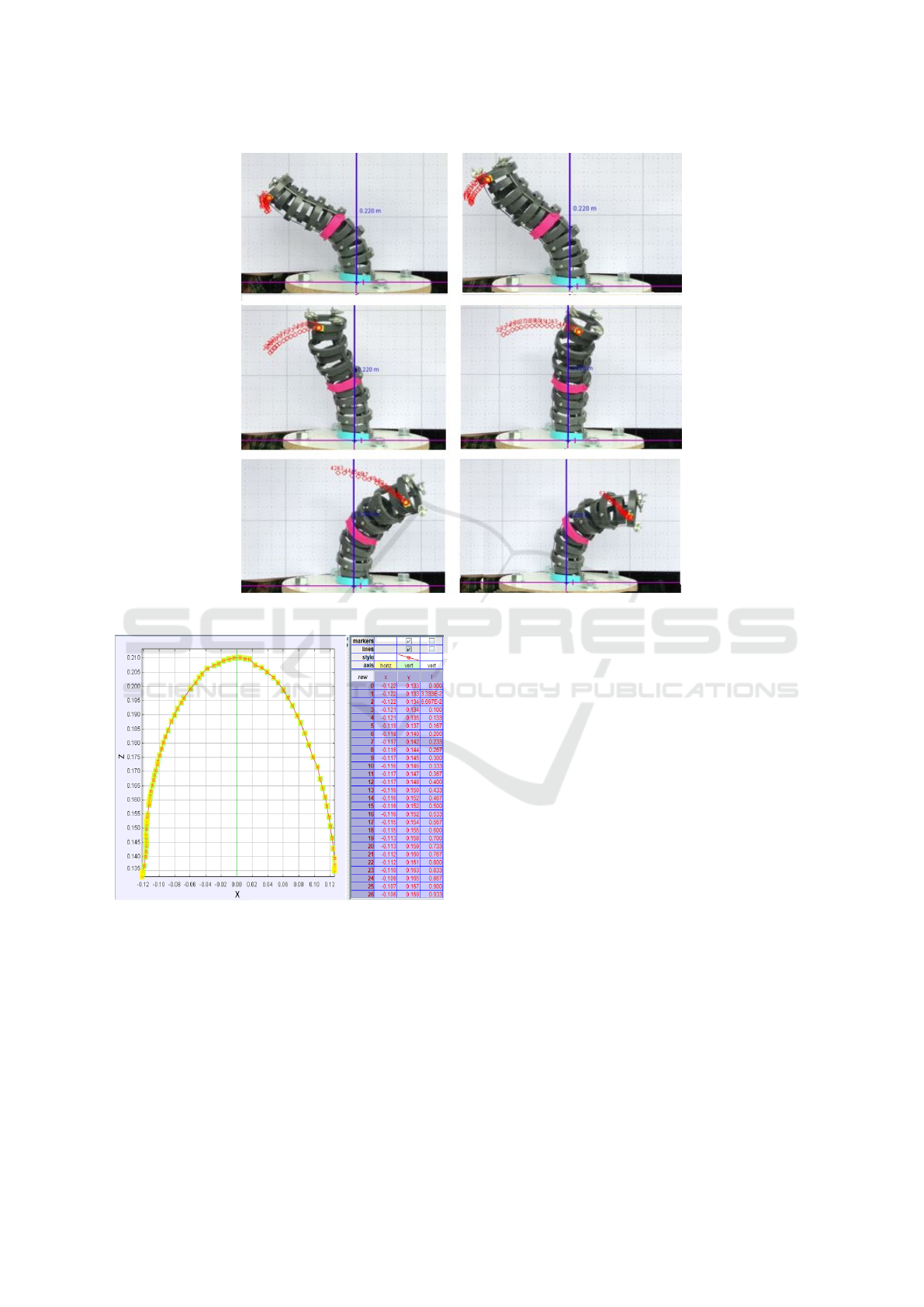
Figure 7: Tracking Position of Robot Continuum using video Tracker.
Figure 8: Tracking Position of Robot Continuum using vi-
deo Tracker: Bending Movement Results
sults we concluded that it is possible to implement a
continuum robot structure with minimal positioning
errors, however, it must be taken into account that
adding more segments to the robot will increase the
complexity of the system due to the increase in the
number of cables and actuators in the system.
A modular continuum robot manipulator was pro-
posed, whose length can be extended by adding secti-
ons to the segments (links) and, in turn, define new
configurations by extending the length of the mani-
pulator by adding new segments. This functionality
would allow the continuum robot manipulator to track
trajectories in the combination of a concave and con-
vex radius of curvature that could be used to perform
spatial shifts and obstacle avoidance. Another advan-
tage of the design of the segments of this robot ma-
nipulator is that it is built with fairly light material
and allows to scale its cross-sectional area, which can
be used in different applications, either for guided se-
arches in disaster areas or for applications of health.
The experimental setup allowed to validate the mat-
hematical model and identify the proposed modular
link design.
ACKNOWLEDGEMENTS
This work is supported by a grant from the El Bosque
University and the Research Vice-rectory with the
project number PCI-2017-8832.
The authors would like to thanks to the Professor
Michal Canu for his constant aid in the control aspect.
The authors also wish to thank the Electronic En-
gineering and Bioengineering programs of the Fa-
culty of Engineering of El Bosque University for all
the support received.
ICINCO 2018 - 15th International Conference on Informatics in Control, Automation and Robotics
216

Figure 9: Comparison between different movements, their average and the calculated trajectory.
REFERENCES
Burgner, J., Rucker, D. C., Gilbert, H. B., Swaney, P. J.,
Russell, P. T., Weaver, K. D., and Webster, R. J.
(2014). A telerobotic system for transnasal sur-
gery. IEEE/ASME Transactions on Mechatronics,
19(3):996–1006.
Burgner-Kahrs, J., Rucker, D. C., and Choset, H. (2015).
Continuum Robots for Medical Applications: A Sur-
vey. IEEE Transactions on Robotics, 31(6):1261–
1280.
Chirikjian, G. S. and Burdick, J. W. (1995a). Kinematically
Optimal Hyper-Redundant Manipulator Configurati-
ons. IEEE Transactions on Robotics and Automation,
11(6):794–806.
Chirikjian, G. S. and Burdick, J. W. (1995b). The Kine-
matics of Hyper-Redundant Robot Locomotion. IEEE
Transactions on Robotics and Automation, 11(6):781–
793.
Crespi, A., Badertscher, A., Guignard, A., and Ijspeert, A. J.
(2005). AmphiBot I: An amphibious snake-like robot.
Robotics and Autonomous Systems, 50(4):163–175.
DHB (2013). Differential Geometry. Reading, (4):0.
Hannan, M. W. and Walker, I. D. (2003). Kinematics and
the implementation of an elephant’s trunk manipulator
and other continuum style robots. Journal of Robotic
Systems, 20(2):45–63.
Hirose, S. (1995). Biologically Inspired Robots: Snake-
Like Locomotors and Manipulators. Applied Mecha-
nics Reviews, 48(3):B27–B27.
Jones, B. A., McMahan, W., and Walker, I. D. (2006).
Practical Kinematics for Real-Time Implimentation of
Continuum Robots. IEEE International Conference
on Robotics and Automation, pages 1840–1847.
Jones, B. A. and Walker, I. D. (2006). Kinematics for multi-
section continuum robots. IEEE Transactions on Ro-
botics, 22(1):43–55.
Laschi, C., Cianchetti, M., Mazzolai, B., Margheri, L., Fol-
lador, M., and Dario, P. (2012). Soft robot arm inspi-
red by the octopus. Advanced Robotics, 26(7):709–
727.
Li, Z., Ren, H., Chiu, P. W. Y., Du, R., and Yu, H. (2016).
A novel constrained wire-driven flexible mechanism
and its kinematic analysis. Mechanism and Machine
Theory, 95:59–75.
Li, Z., Wu, L., Ren, H., and Yu, H. (2017). Kinematic com-
parison of surgical tendon-driven manipulators and
concentric tube manipulators. Mechanism and Ma-
chine Theory, 107(September 2016):148–165.
Liu, S., Yang, Z., Zhu, Z., Han, L., Zhu, X., and Xu, K.
(2016). Development of a dexterous continuum ma-
nipulator for exploration and inspection in confined
spaces. Industrial Robot: An International Journal,
43(3):284–295.
Ma, S., Hirose, S., and Yoshinada, H. (1994). Develop-
ment of a hyper-redundant multijoint manipulator for
maintenance of nuclear reactors. Advanced Robotics,
9(3):281–300.
Mahl, T., Hildebrandt, A., and Sawodny, O. (2014). A Vari-
able Curvature Continuum Kinematics for Kinematic
Control of the Bionic Handling Assistant. 30(4):1–15.
McMahan, W., Chitrakaran, V., Csencsits, M., Dawson, D.,
Walker, I. D., Jones, B., Pritts, M., Dienno, D., Gris-
som, M., and Rahn, C. D. (2006). Field trials and tes-
ting of the OcotArm continuum manipulator. Procee-
dings of the 2006 IEEE international conference on
robotics and automation (ICRA), (May):2336–2341.
Meng, G. Z., Yuan, G. M., Liu, Z., and Zhang, J. (2013).
Forward and Inverse Kinematic of Continuum Robot
for Search and Rescue. Advanced Materials Research,
712-715:2290–2295.
Pires, N. (2007). Robot Manipulators and Control Systems.
Industrial Robots Programming. Building Applicati-
ons for the Factories of the Future.
Robotics OC (2016). LaserPipe Remote in-bore laser wel-
ding of industrial pipelines.
Tiefeng, S., Libin, Z., Mingyu, D., Guanjun, B., and Qing-
hua, Y. (2015). Fruit harvesting continuum manipula-
tor inspired by elephant trunk. International Journal
Constant Curvature Kinematic Model Analysis and Experimental Validation for Tendon Driven Continuum Manipulators
217

of Agricultural and Biological Engineering, 8(1):57–
63.
Walker, I. D. (2013). Continuous Backbone Continuum Ro-
bot Manipulators. ISRN Robotics, 2013:1–19.
Webster, R. J. and Jones, B. A. (2010). Design and kinema-
tic modeling of constant curvature continuum robots:
A review. International Journal of Robotics Research,
29(13):1661–1683.
ICINCO 2018 - 15th International Conference on Informatics in Control, Automation and Robotics
218
