
A Trajectory Controller for Kite Power Systems
with Wind Gust Handling Capabilities
Manuel C. R. M. Fernandes, Gonc¸alo B. Silva, Lu
´
ıs Tiago Paiva and Fernando A. C. C. Fontes
SYSTEC–ISR, Faculdade de Engenharia, Universidade do Porto,
Rua Dr. Roberto Frias, Porto, Portugal
Keywords:
Renewable Energy, Airborne Wind Energy, Kite Power Systems, Nonlinear Systems, Path-following Control,
Safe Mode Control.
Abstract:
In this paper, we address the generation of electrical power using Airborne Wind Energy Systems, comprising
a kite connected through a tether to a generator on the ground. We design a controller to steer the kite to
follow a pre-defined periodic path, which includes a production mode, a tether retrieval mode, and a safe
mode capable of handling wind gusts.
1 INTRODUCTION
Electrical energy is crucial to satisfy modern human
needs, while the amount of energy available is directly
associated with development. Currently, the majority
of electrical energy generated worldwide comes from
fossil and nuclear fuels, which are now facing increas-
ing societal concerns of environmental sustainability.
To address these problems, countries are enact-
ing energy policies to encourage the use of renew-
able energies. In this context, in the last decades
there has been a fast growth and development of re-
newable energy systems. Very recently, Portugal’s to-
tal renewable energy production in March 2018 ex-
ceeded the country’s electricity consumption for the
month. Among the renewable energy sources, wind
is an important large scale alternative. Wind energy
is nowadays mainly extracted on-shore at low heights
by wind turbines mounted on towers with a few dozen
meters (50-200 m) and, despite the significant num-
ber, still growing, of wind farms, most of the existing
wind energy remains unexploited since it is available
at high altitudes and off-shore.
One of the promising technologies to exploit the
stronger and more consistent high altitude and off-
shore winds is Airborne Wind Energy (AWE), namely
Kite Power Systems (Ahrens et al., 2013; Schmehl,
2018). These systems use a kite, with flexible or rigid
wing, that is connected to a generator through a ca-
ble (tether). Most of such systems are based on ex-
ploiting crosswind kite power described by Loyd in
1980 (Loyd, 1980). The huge power that can poten-
tial be harvested from AWE systems is supported by
the facts that wind speeds grow fast with height and
that the aerodynamic lift is proportional to the square
of the apparent wind velocity
~
F
lift
=
1
/2c
L
(α)Av
2
a
. (1)
Thus, the maximum power extraction is obtained
when the kite flies at high speeds in direction perpen-
dicular to the direction of the wind, which requires
this trajectory to be periodic.
In a kite power system with a fixed generator on
the ground, which is our case, electrical power is gen-
erated as the kite rises by the wind, which causes the
cable to be unrolled and subsequently the generator
to produce electricity (see Figure 1). Since the cable
length is finite, when we reach that limit the cable is
retrieved with a minimum energy expenditure and the
process is repeated.
To automate this process and guarantee a positive
net power output it is necessary to design a controller
taking into account variations in wind direction and
intensity, among other factors.
Using a 3D simulation model of the kite dynam-
ics, considering all the forces acting on it, we design
a controller to follow a desired path. Then we ad-
dress the problem of handling wind gusts. When wind
reaches a certain speed threshold, where tether force
might be excessive, we activate gust mode in order to
prevent damage to the kite or other components. We
do this by stopping the kite reel-out (or reel-in, in case
the gust occurs in recovery mode), and directing it up-
wards to an equilibrium inclination. We set the angle
Fernandes, M., Silva, G., Paiva, L. and Fontes, F.
A Trajectory Controller for Kite Power Systems with Wind Gust Handling Capabilities.
DOI: 10.5220/0006914205330540
In Proceedings of the 15th International Conference on Informatics in Control, Automation and Robotics (ICINCO 2018) - Volume 1, pages 533-540
ISBN: 978-989-758-321-6
Copyright © 2018 by SCITEPRESS – Science and Technology Publications, Lda. All rights reserved
533

Table 1: Nomenclature.
A wing reference area of kite
m
2
R
GL
rotation matrix from G to L
a
t
tether reel–out acceleration
ms
−2
R
LG
rotation matrix from L to G
c
D
aerodynamic drag coefficient r tether length [m]
c
L
aerodynamic lift coefficient ρ air density
kgm
−3
E energy produced [Ws] T tether tension [N]
~
F
aer
aerodynamic force [N] v
a
apparent wind velocity
ms
−1
~
F
drag
drag force [N] v
w
wind velocity
ms
−1
~
F
cent
centrifugal force [N] v
t
tether reel–out velocity
ms
−1
~
F
cor
Coriolis force [N] u control vector
~
F
lift
aerodynamic lift force [N] x state vector
~
F
inert
inertial forces [N] α angle of attack [rad]
~
F
th
tether force [N] φ azimuthal angle [rad]
g gravitational acceleration
ms
−2
β elevation angle [rad]
m mass [kg] ψ roll angle [rad]
P power produced [W] γ reference tracking angle [rad]
p kite position [m] τ local tangent plane
Figure 1: Example of a kite power system in the reel-out
phase (Argatov et al., 2009).
of attack to a high value, in order to have a low lift
force and consequently a low tether tension force.
This technology is still not completely developed
at a commercial stage. Therefore, there is a win-
dow of opportunity for new challenges, namely in
the development of new controllers and continuous
improvements to existing methodologies. A similar
principle can be applied when the kite moves in an-
other fluid, such as water. An example is explored in
(Paiva and Fontes, 2017).
In the approach proposed here, the trajectory con-
troller acts on the roll angle to change the kite heading
direction in order to follow a moving reference point
belonging a desired path (see (Prodan et al., 2015),
(Caldeira and Fontes, 2010) for other approaches on
path-following control). Also, a innovative wind gust
mode is developed and tested. The numerical results
report that such strategy allows us to handle strong
wind velocities, preventing the system to crash, with-
out having to completely retract the kite.
This paper is organized as follows. In section 2,
we describe a model for the kite power system. In
section 3, we describe the design of a controller that
allows the kite to follow a desired path. In section 4,
we address the wind gust problem and how we handle
it. In section 5, we provide results obtained from our
simulations. In section 6, we summarize the conclu-
sions.
2 KITE POWER SYSTEM MODEL
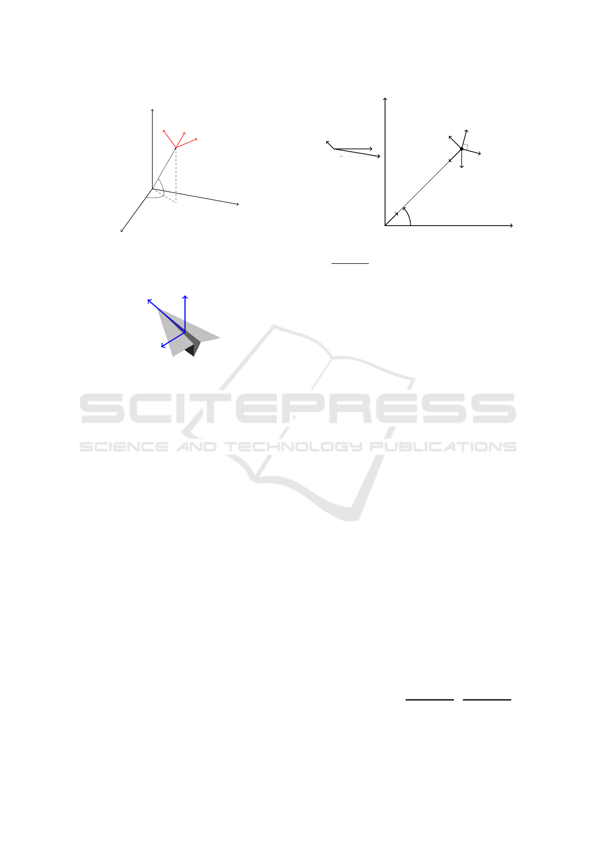
2.1 Coordinate System
The dynamics of the kite are modelled in a spherical
coordinate system positioned at the center of mass of
the kite, see (Paiva and Fontes, 2018; Canale et al.,
2010). We consider three coordinate systems:
Global G: An inertial Cartesian coordinate system
(x,y,z) where the origin is on the ground at the
point of attachment of the tether and x is aligned
according to the wind direction v
w
= (v
w
,0,0).
The basis of this coordinate system is (
~
e
x
,
~
e
y
,
~
e
z
).
Local L: A non-inertial spherical coordinate system
(r, φ, β). The basis of this coordinate system is
(
~
e
r
,
~
e
φ
,
~
e
β
) (Fig. 2).
Body B: A non-inertial Cartesian coordinate system
attached to the kite body. The basis of this co-
ordinate system is (
~
e
1
,
~
e
2
,
~
e
3
), with
~
e
1
coinciding
with the kite longitudinal axis pointing forward,
~
e
2
in the kite transversal axis pointing to the left
ICINCO 2018 - 15th International Conference on Informatics in Control, Automation and Robotics
534
x
y
z
r
φ
β
e
φ
e
β
e
r
Figure 2: Global and Local coordinate systems (Paiva and
Fontes, 2018) .
e
1
e
2
e
3
Figure 3: Body coordinate system (Paiva and Fontes, 2018).
wing tip, and
~
e
3
in the kite vertical axis pointing
upwards (Fig. 3).
We consider the position
p =
x
y
z
=
r cos(β) cos(φ)
r cos(β) sin(φ)
r sin(β)
,
the rotation matrix from L coordinate system to G
R
LG
=
~
e
r
~
e
φ
~
e
β
=
=
cos(β)cos(φ) −sin(φ) −sin(β)cos(φ)
cos(β)sin(φ) cos(φ) −sin(β)sin(φ)
sin(β) 0 cos(β)
,
and the rotation matrix from G coordinate system to
L
R
GL
= R
−1
LG
= R
>
LG
.
The apparent wind velocity is v
a
= v
w
−
˙
p. We
assume that its radial component v
a,r
is strictly pos-
itive and that the kite body longitudinal axis aligns
naturally with the apparent wind velocity, that is
~
e
1
=
−v
a
/kv
a
k. Consider the local tangent plane τ, which
tangent to a sphere centred at the origin and contains
the axis
~
e
φ
and
~
e
β
.
Let ψ be the roll angle measuring rotation around
the longitudinal axis (
~
e
1
). We consider that initially,
for ψ = 0,
~
e
2
is in the plane τ. Define ˜e
2
to be the
“unrotated” axis, with ˜e
2
=
~
e
2
when ψ = 0. We have
that ˜e
2
⊥
~
e
r
, and ˜e
2
⊥
~
e
1
. Thus, we can then define
v
w
˙p
v
a
β
r
~
F
lift
~
F
drag
~
F
grav
~
F
th
T
e
β
Figure 4: Forces acting on the kite (Paiva and Fontes, 2018).
˜e
2
=
~
e
r
×
~
e
1
k
~
e
r
×
~
e
1
k
. Finally, we consider the kite body has
an anti-clockwise rotation of ψ around the
~
e
1
axis: the
roll angle.
We assume here that the roll angle ψ can be con-
trolled directly. For example, in a two line kite where
d is the distance between attachment points and ∆r
is the relative difference between the lengths of each
line, we have sinψ = ∆r/d (cf. (Diehl, 2001)). Using
Rodrigues’ formula to rotate ˜e
2
by ψ around
~
e
1
, we
obtain
~
e
2
= ˜e
2
cosψ + (
~
e
1
× ˜e
2
)sinψ +
~
e
1
(
~
e
1
· ˜e
2
)(1 − cos ψ)
and finally, we define
~
e
3
to be
~
e
3
=
~
e
1
×
~
e
2
.
2.2 Acting Forces
The total force acting on the kite can be decomposed
into the tether, gravity, and aerodynamical compo-
nents (see Fig. 4)
m
¨
p =
~
F
th
+
~
F
grav
+
~
F
aer
(α) (2)
where
~
F
th
= −T
~
e
r
=
−T
0
0
L
,
~
F
grav
= −mg
~
e
z
=
0
0
−mg
G
=
−mg sin β
0
−mg cos β
L
,
~
F
aer
(α) =
1
/2ρAkv
a
k
2
(c
L
(α)
~
e
3
− c
D
(α)
~
e
1
).
In the local coordinate system
¨
p =
¨r
r
¨
φcos(β)
r
¨
β
L
+
−r
˙
β
2
− r
˙
φ
2
cos
2
(β)
2˙r
˙
φcos(β) − 2r
˙
φ
˙
βsin(β)
2˙r
˙
β + r
˙
φ
2
cos(β)sin(β)
L
| {z }
−
1
/m
~
F
inert
(3)
A Trajectory Controller for Kite Power Systems with Wind Gust Handling Capabilities
535

where the second term is −
1
/m
~
F
inert
with
~
F
inert
repre-
senting the inertial forces (centrifugal and Coriolis) in
the local coordinate system.
Denoting the total resulting force by F, we have
F = m
¨r
r
¨
φcos(β)
r
¨
β
=
~
F
th
+
~
F
grav
+
~
F
aer
(α) +
~
F
inert
(4)
We assume that the tether acceleration ¨r can be con-
trolled directly by a
t
. Denoting by T the tension on
the tether at the base, we have T = F
r
− ma
t
. We also
assume that the angle of attack α and the roll an-
gle ψ can be controlled directly, possibly by varying
the differential lengths of the cable in the kite bridle.
Defining the state x =
r, φ, β, ˙r,
˙
φ,
˙
β
and the control
u = (a
t
,α,ψ), the dynamic equation is
˙
x(t) = f (x(t),u(t))
=
d
dt
r
φ
β
˙r
˙
φ
˙
β
=
˙r
˙
φ
˙
β
a
t
1
mr cos(β)
F
φ
1
mr
F
β
. (5)
2.3 Equilibrium Inclination
In strong winds or when the tether is being recoiled
sufficiently fast, it is possible to maintain the kite at
an equilibrium point with β = β
?
, φ = 0, and with the
angular velocities and angular accelerations equal to
zero.
Consider the case of high values of the appar-
ent wind speed, when the aerodynamical lift force is
much higher than gravity. In such case
~
T =
~
F
lift
+
~
F
drag
and when ˙r = 0, the drag is aligned with the wind,
horizontal, and the lift is vertical. Therefore
β
?
= arctan
~
F
lift
~
F
drag
!
= arctan
c
L
c
D
When the angle of attack varies between 0
o
and
12
o
degrees, the equilibrium inclination varies be-
tween 87
o
and 85
o
. For higher angles of attack, we
obtain lower lift to drag ratios and lower equilibrium
inclinations. At 13.3
o
we have a β
∗
= 76
o
.
3 TRAJECTORY CONTROLLER
The total cycle consists of a production phase when
the tether is reeled-out (˙r > 0) until a maximum value
of tether length r
max
is attained. Then, follows a re-
traction phase when the tether is reeled-in (˙r < 0) until
a minimum value of tether length r
min
is attained.
In order to have a predictable behaviour and op-
timize the energy produced by the system, the kite
should track a pre-defined path. In the production
phase, we define the path of Figure 5 in the spherical
rectangle β ∈ [30, 50], φ ∈ [−40,+40] degrees, where
the kite should move almost cross wind. In the retrac-
tion phase, the kite goes to the vertical plane φ = 0,
raises the elevation angle to the equilibrium inclina-
tion, and pulls back the tether.
We define the desired production path on a (φ,β)
coordinate system, making it independent of the
tether length. We use a reference target approach to
control the heading direction of the kite. Given the
position of the mass-point of the kite p(φ,β) not in
the desired path, we determine the closest point to the
desired path (A). Then, a reference target B is defined
as the point distancing L from A in a forward direction
along the path. An auxiliary vector
~
L
1
is computed
between p and B (see Figure 5).
Finally, we compute the angle (γ) between the kite
velocity ˙p and
~
L
1
, which serves as a reference to the
desired heading direction adjustment, so that the de-
sired path is rejoined at B. In order to control the an-
gle (γ) towards zero, we act on the roll angle ψ using a
proportional controller: ψ(t) = Kγ(t). The kite trajec-
tory control through the heading directions, acting on
the roll angle using a proportional controller has been
shown to be an adequate steering command (Fagiano
et al., 2014).
L
A B
p
L
1
˙p
γ
Figure 5: Trajectory Controller.
ICINCO 2018 - 15th International Conference on Informatics in Control, Automation and Robotics
536

4 HANDLING WIND GUST
Although the trajectory controller system is resilient
enough to support certain strong wind velocities, the
resultant tether tension force might be overwhelming
for the kiteline or other components. Therefore, for
security purposes, a method to handle wind gusts in a
robust way is crucial.
The chosen response strategy for wind velocities
that we consider above the safety limit consists in el-
evating the kite towards the zenith, to an equilibrium
inclination and centring it (i.e. φ=0), by controlling
the roll angle ψ (see Figure 7). Also, the tether reel-
ing is stopped and the angle of attack is set to a high
value, guaranteeing a low lift force and a high drag,
stalling and decelerating the kite. The low lift force
minimizes the tether tension and the stalling avoids
uncontrollable movements.
When the wind velocity returns to lower values,
the system resumes the normal production or retrac-
tion phase, depending on which phase was interrupted
by the wind gust.
Simulation results are described in the next sec-
tion.
5 SIMULATION RESULTS
We consider the simulation parameters of the kite sys-
tem defined in table 2.
Table 2: Simulation Parameters.
Parameter Value
ρ 1.2 kgm
−3
v
w
10 ms
−1
g 9.8 m s
−2
m 0.7 kg
A 0.28 m
2
The aerodynamic coefficients were obtained by
making a linear regression from data in (UIUC, 2018).
c
L
(α) = 0.3 + 0.1α, 0 < α < 12
c
L
(α) = 9.9 − 0.7α, 12 < α < 15
c
D
(α) = 0.012 + 0.01α
For the simulations we use the software Simulink,
where we build the model presented above and design
the controllers.
5.1 Fixed Tether Length
We start by simulating how the kite reacts to a wind
gust when the tether is on a fixed length. As we can
see in Figure 7, the kite follows the prescribed path
and when the gust begins, the kite elevates to an equi-
librium inclination and is centred in φ. When the wind
velocity returns to normal values, the kite descends
and resumes to follow the desired path.
As we can see in Figure 8, when the gust mode
is activated, the tether force is small, as is desirable
when handling strong winds. In this simulation we
have first a wind velocity of 10 m s
−1
, then we in-
crease the velocity to 30 m s
−1
, above the wind gust
threshold, and finally we reduce it to 20 ms
−1
.
5.2 Complete Production Cycle
Now we see an example of a complete production cy-
cle, with the reel-out and reel-in of the tether. As we
can see on figure 9, as the kite rises and a wind gust
occurs, the reeling out of the tether is stopped and the
kite is elevated to an equilibrium point, returning to
the trajectory as wind velocities return to lower val-
ues.
On figure 11 we can see the state variables (r,φ,β).
We clearly see the wind gust occurring between
[200,250]s, as r stays constant, φ goes to zero and the
elevation angle β rises. On figure 12 we can see the
control variables, and as supposed, during the wind
gust we have a high angle of attack (α) and ψ is zero
since the kite is centered on φ = 0. Finally, on figure
10, we can see energy is produced during the reel-
out phase, and a negligible amount is spent during the
reel-in phase. During the gust mode, energy is neither
produced or spent.
6 CONCLUSIONS
Using a 3D dynamic simulation model of a kite power
system, considering the forces acting on it, we de-
velop here a method to control the kite to follow a
pre-defined path. The prescribed path is defined only
by the minimum and maximum values of φ and β,
independently of the tether length and reel in veloc-
ity. The steering controller in the production path-
following phase is based on the adjustment of the roll
angle (ψ), working with a constant angle of attack.
Although this procedure has shown itself robust for
high wind speeds, a safety mode to avoid excessive
strain on the tether and other components was devel-
oped.
A Trajectory Controller for Kite Power Systems with Wind Gust Handling Capabilities
537
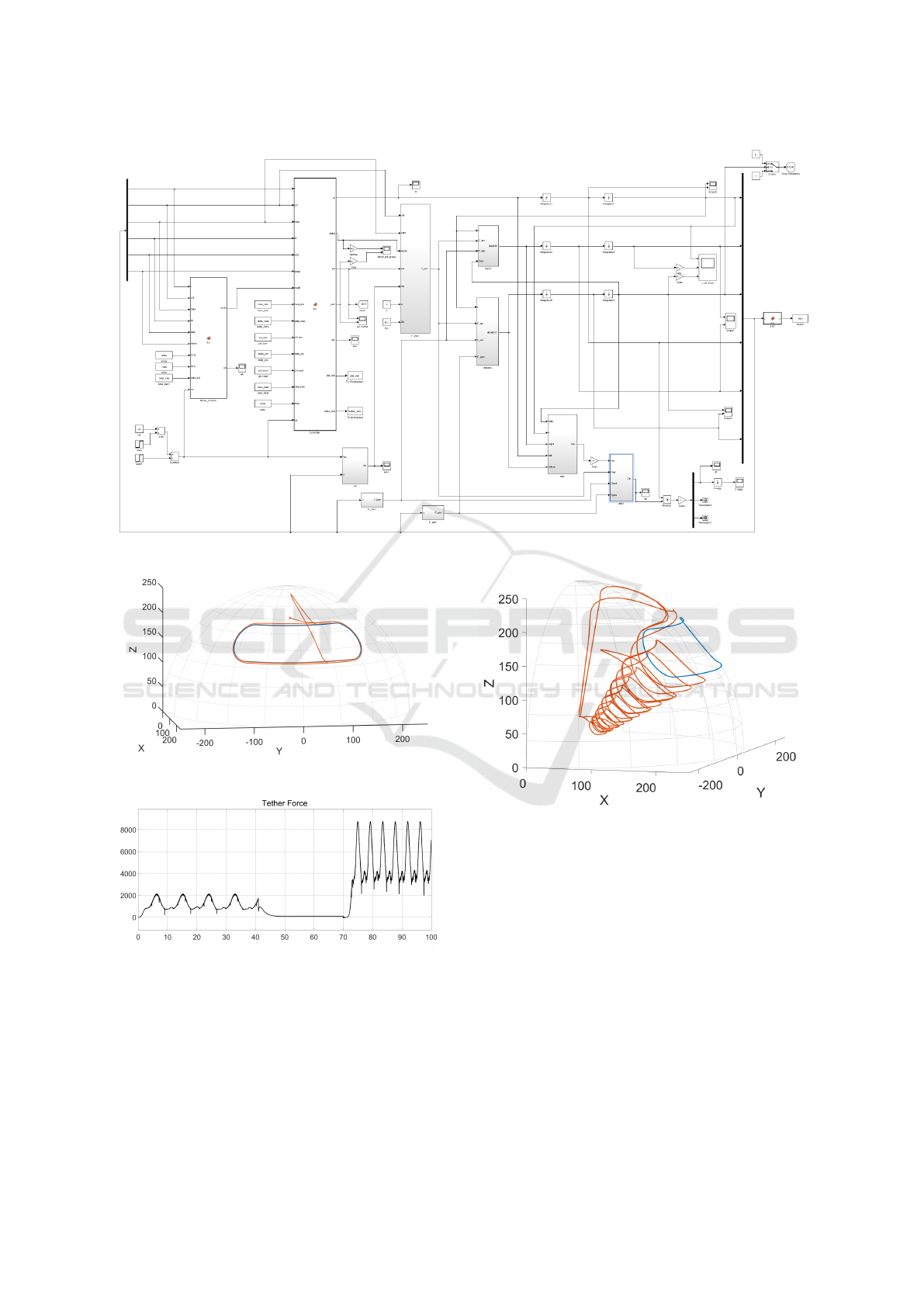
Figure 6: Simulink System.
Figure 7: Kite reacting to wind gust.
Figure 8: Tether force.
The angle of attack plays an important roll to bal-
ance both drag and lift aerodynamic forces and the
resultant tether tension. In the event of wind gusts,
we adjust the angle of attack to an appropriate value
that decreases the tether tension. Moreover, at the
same time the kite is driven towards the zenith where
it can handle the excessive energy contained in the
wind gust.
Figure 9: Trajectory example with wind gust.
ACKNOWLEDGEMENTS
We acknowledge the support of FEDER/-
COMPETE2020/NORTE2020/POCI/PIDDAC/-
MCTES/FCT funds through grants SFRH/BPD/-
126683/2016, PTDC-EEI-AUT-2933-2014|16858–
TOCCATA, and 02/SAICT/2017-31447|POCI-01-
0145-FEDER-031447|FCT–UPWIND.
REFERENCES
Ahrens, U., Diehl, M., and Schmehl, R., editors (2013). Air-
borne Wind Energy. Green Energy and Technology.
ICINCO 2018 - 15th International Conference on Informatics in Control, Automation and Robotics
538
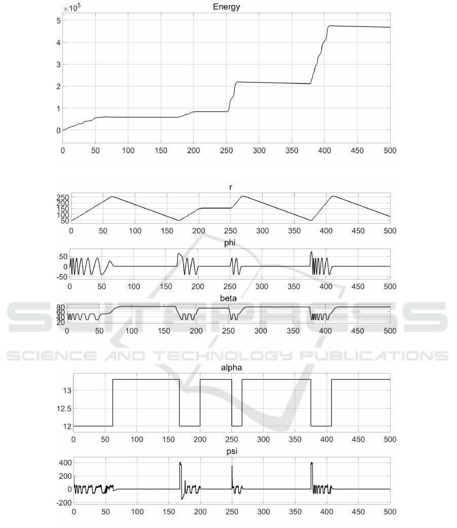
Figure 10: Energy production.
Figure 11: State variables - (r, φ,β).
Figure 12: Control variables - (α,ψ).
Springer Berlin Heidelberg, Berlin, Heidelberg.
Argatov, I., Rautakorpi, P., and Silvennoinen, R. (2009). Es-
timation of the mechanical energy output of the kite
wind generator. Renewable Energy, 34(6):1525–1532.
Caldeira, A. C. D. and Fontes, F. A. C. C. (2010). Model
predictive control for path-following of nonholonomic
systems. In Proceedings of the 10th Portuguese Con-
ference on Automatic Control - CONTROLO 2010,
pages 720–725, Coimbra, Portugal.
Canale, M., Fagiano, L., and Milanese, M. (2010). High
Altitude Wind Energy Generation Using Controlled
Power Kites. IEEE Transactions on Control Systems
Technology, 18(2):279 –293.
Diehl, M. (2001). Real-time optimization for large scale
nonlinear processes. PhD Thesis.
Fagiano, L., Zgraggen, A. U., Morari, M., and Khammash,
A Trajectory Controller for Kite Power Systems with Wind Gust Handling Capabilities
539

M. (2014). Automatic crosswind flight of tethered
wings for airborne wind energy: modeling, control de-
sign and experimental results. IEEE Transactions on
Control Systems Technology, 22(4):1433–1447.
Loyd, M. L. (1980). Crosswind kite power. Journal of En-
ergy, 4(3):106–111.
Paiva, L. T. and Fontes, F. A. C. C. (2017). Optimal control
of underwater kite power systems. In Energy and Sus-
tainability in Small Developing Economies (ES2DE),
2017 International Conference in, pages 1–6. IEEE.
Paiva, L. T. and Fontes, F. A. C. C. (2018). Optimal Control
Algorithms with Adaptive Time-Mesh Refinement for
Kite Power Systems. Energies, 11(3):475.
Prodan, I., Olaru, S., Fontes, F. A. C. C., Pereira, F. L.,
Sousa, J. B. d., Maniu, C. S., and Niculescu, S.-
I. (2015). Predictive Control for Path-Following.
From Trajectory Generation to the Parametrization of
the Discrete Tracking Sequences. In Developments
in Model-Based Optimization and Control, Lecture
Notes in Control and Information Sciences, pages
161–181. Springer, Cham.
Schmehl, R., editor (2018). Airborne Wind Energy: Ad-
vances in Technology Development and Research.
Green Energy and Technology. Springer Singapore.
UIUC (2018). UIUC Airfoil Data Site. The University of
Illinois at Urbana-Champaign. Acessed 2018-05-07.
ICINCO 2018 - 15th International Conference on Informatics in Control, Automation and Robotics
540
