
Transformation Method from Scenario to Sequence Diagram
Yousuke Morikawa, Takayuki Omori and Atsushi Ohnishi
Department of Computer Science, Ritsumeikan University, Kusatsu, Shiga, Japan
Keywords: Scenario, Sequence Diagram, Transformation between Scenario and Sequence Diagram.
Abstract: Both scenario and sequence diagram are effective models for specifying behaviours of the target systems.
Scenarios can be used for requirements elicitation in the requirements definition. Sequence diagrams can be
used for interactions between a system user and system, and between objects. If these two models
specifying behaviours of the same system, these models should be consistent. In this paper, we propose a
transformation method from a scenario written with a structured scenario language named SCEL to a
sequence diagram written with PlantUML. The transformation method will be illustrated with an example.
1 INTRODUCTION
Scenarios are important in software development,
particularly in requirements engineering, by
providing concrete system description
(Weidenhaupt, 1998). Especially, scenarios (or use
case descriptions) are useful in defining system
behaviours by system developers and validating the
requirements by customers.
Sequence diagrams may be used to specify
software behaviours in the later phases of the object-
oriented software development. In such a case,
because scenarios and sequence diagrams represent
behaviours of the same target software system, these
two models should be consistent. If there exist
inconsistent parts of these models, software cannot
be successfully developed.
In this paper, we propose a transformation
method from a scenario to a sequence diagram. This
method enables to eliminate or lessen the
inconsistency between these two models and
improve the efficiency and the correctness of
generated models. We adopt SCEL as a scenario
description language and PlantUML as a language
for describing a sequence diagram. PlantUML is a
text-base language for describing UML models
(PlantUML, 2018).
The paper is organized as follows. The next
section briefly introduces a scenario description
language named SCEL. In section 3, PlantUML will
be briefly introduced. In section 4, we describe a
transformation method between a scenario written
with SCEL and a sequence diagram written with
PlantUML. In section 5 we discuss the proposed
method and a prototype system based on the method.
In section 6, we discuss related works. In the last
section we give concluding remarks.
2 SCENARIO DESCRIPTION
LANGUAGE: SCEL
A scenario can be regarded as a sequence of events.
Events are behaviours employed by users or the
system for accomplishing their goals. We assume
that each event has just one verb, and that each verb
has its own case structure (Fillmore, 1968). The
scenario language has been developed based on this
concept. Verbs and their own case structures depend
on problem domains, but the roles of cases are
independent of problem domains. The roles include
agent, object, recipient, instrument, source, etc.
(Fillmore, 1968; Ohnishi, 1996). Verbs and their
case structures are provided in a dictionary of verbs.
If a scenario describer needs to use a new verb, he
can use it by adding the verb and its case structure in
the dictionary.
We adopt a requirements frame in which verbs
and their own case structures are specified. The
requirements frame depends on problem domains.
Each action has its case structure, and each event
can be automatically transformed into internal
representation based on the frame. In the
transformation, concrete words will be assigned to
pronouns and omitted indispensable cases. With
136
Morikawa, Y., Omori, T. and Ohnishi, A.
Transformation Method from Scenario to Sequence Diagram.
DOI: 10.5220/0006915001360143
In Proceedings of the 10th International Joint Conference on Knowledge Discovery, Knowledge Engineering and Knowledge Management (IC3K 2018) - Volume 3: KMIS, pages 136-143
ISBN: 978-989-758-330-8
Copyright © 2018 by SCITEPRESS – Science and Technology Publications, Lda. All rights reserved
Requirements Frame, we can detect both the lack of
cases and the illegal usage of noun types (Ohnishi,
1996). Our scenario language defines the semantics
of verbs with their case structure. For example, data
flow concept has source, goal, object, and
instrument cases.
Figure 1 shows a scenario of reservation of train
seat written with our scenario language, SCEL.
[Title: reservation of a train seat]
[Viewpoints: passenger, clerk, reservation
system]
1. A passenger passes his itinerary to a
clerk.
2. The clerk retrieves empty seats to
reservation system.
3. The system shows a list of empty seats
to the clerk.
4. The clerk shows the list to the passenger
5. The passenger selects his seat from the
list.
6. The clerk sends request for seat
reservation to the system,
7. The system reserves the seat
8. The system sends a successful message
to the clerk.
9. The passenger passes his credit card to
the clerk.
10. The clerk charges the fare to the credit
card.
11. If the credit card is valid then the clerk
issues train ticket with seat reservation.
12. The clerk passes the credit card and
ticket to the passenger.
13. fi
Figure 1: Scenario example.
A title of the scenario is given at the first line of
the scenario in Figure 1. Viewpoints of the scenario
are specified at the second line. In this paper,
viewpoints mean active objects such as human, and
system appearing in the scenario. There exist three
viewpoints, namely “passenger,” “clerk,” and
“reservation system.” The order of the specified
viewpoints means the priority of the viewpoints. In
this example, the first prior object is “passenger,”
and the second is “clerk,” and the third one is
“reservation system.” If two or more objects in the
list of viewpoints exist in an event, the prior object
becomes a subject of an event.
In this scenario, all of the events are sequential
except for the 11th conditional event. Actually,
event number is for reader’s convenience and not
necessary.
Each event is automatically transformed into
internal representation. The details of transformation
mechanism is in (Ohnishi, 1996). For example, the
1st event “A passenger passes his itinerary to clerk”
can be transformed into internal representation
shown in Table 1. In this event, the verb “pass”
corresponds to the concept “data flow.” The data
flow concept has its own case structure with four
cases, namely to say, source case, goal case, object
case and instrument case. Sender corresponds to the
source case and receiver corresponds to the goal
case. Data transferred from source case to goal case
corresponds to the object case. Device for sending
data corresponds to the instrument case.
In this event, “(his) itinerary” corresponds to the
object case and “passenger” corresponds to the
source case. “Clerk” corresponds to goal case. The
instrument case is optional, while the other cases are
indispensable.
Table 1: Internal representation of the 1st event in Figure 1.
Concept: DFLOW (Data Flow)
source goal object instrument
passenger clerk itinerary NOT
Specified
Scenarios with SCEL can include not only
sequence of events, but also scenario title, and
viewpoints. The first line in Figure 1 shows title of
the scenario. The second line shows viewpoints of
the scenario. Viewpoints mean active objects, such
as human, system, function in the scenario. In Figure
1, the first and primary viewpoint is “passenger,”
and the second and secondary one is “clerk,” and
“reservation system” is the third priority object.
These viewpoints become subjects of events.
Actually, subjects of events in Figure 1 are
“passenger,” “clerk,” or “(reservation) system.”
We assume seven kinds of time sequences
among events: 1) sequence, 2) selection, 3) iteration,
4) AND-fork, 5) OR-fork, 6) XOR(exclusive OR)-
fork, 7) AND/OR/XOR-join (Zhang 2004). Because
most events are sequential, so a list of events means
sequential events like the scenario shown in Figure 1.
The main reason why we use SCEL as a scenario
description language is to keep the abstraction level
of scenarios with SCEL as a certain level. Suppose a
scenario of purchasing a train ticket. One scenario
may consist of just one event of buying a train ticket.
Another scenario may consist of several events, such
as 1) informing date, destination, the number of
passengers, and class of cars, 2) retrieving train data
Transformation Method from Scenario to Sequence Diagram
137
base, 3) issuing a ticket, 4) charging ticket fee to a
credit card, and so on. If the abstract levels of
scenarios are too high, it is quite difficult to
transform them to proper sequence diagrams.
SCEL language for writing scenarios solves this
problem, because SCEL provides limited actions and
their case structure for a specific domain, and
scenarios with SCEL keep a certain abstract level of
actions. As for a system for processing a train ticket,
we can provide several verbs and their case structure
as shown in Table 2.
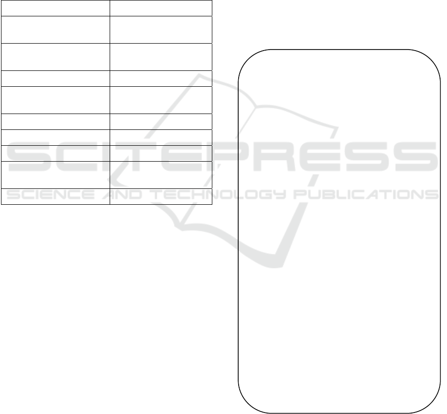
Table 2: Concepts, verbs and cases for train ticket system.
Concept(Verbs) Cases
DFLOW(pass, send, ask
receive, transfer, enter,)
source, goal, object,
instrument*
RET(retrieve)
agent, object goal,
key*
SHOW(show, provide) agent, object, goal
SELECT(select,
choose)
agent, source, object
RESERVE(reserve) agent, object
CHARGE(charge) agent, object1, object2
PRINT(issue, print) agent, object
PAY(pay)
agent, object, goal,
instrument*
VALIDATE(validate) agent, object1, object2
*: optional case
We can use several different verbs to represent
data flow concept, such as “pass,” “send,” and
“receive,” and so on. The first event in Figure 1, “a
passenger passes his itinerary to clerk” can be
differently represented as follows. “Clerk receives
passenger’s itinerary from the passenger” or
“passenger’s itinerary are entered from the
passenger to clerk,” and so on.
The surface representations of these events are
different, but they have the same meaning. These
events are transformed into the same internal
representation as shown in Table 1. We regard
events have the same meaning, if their internal
representations are the same.
Available nouns in scenarios are limited to be
registered in dictionary where nouns and their types
are specified. Six noun types (human, function, data,
file, control, and device) are provided.
We have to prepare noun dictionary and verb
dictionary where concepts, verbs, and their case
structures are specified.
3 PlantUML FOR SEQUENCE
DIAGRAM
PlantUML is a text-based modelling language for
UML models (PlantUML 2018). Figure 2 shows an
example of a sequence diagram of reservation of a
train seat and purchasing ticket. In Figure 2, “title”
shows a title of the diagram, “hide footbox” means
that objects will be suppressed at the bottom of the
diagram, “actor” shows a human object in the
diagram, such as a user, “participant” shows a
system object, “->” shows a message passing, left-
side of the arrow means a sender, right-side of the
arrow means a receiver of the message, “activate”
shows the start of lifeline of objects, and “deactivate”
shows the end of the lifeline of objects, respectively.
@startuml{plantuml_train.png}
title reservation of a train seat
hide footbox
actor passenger as user1
actor clerk as user2
participant “reservation system” as object1
user1 -> user2: travel information
activate user1
activate user2
user2 -> object1: travel information
activate object1
object1 -> object1: retrieve train database
with travel information
object1 -> user2: retrieval result
user2 -> user1: a list of train seats
and corresponding trains
user1 -> user1: select train seat number
and train id from the list
user1 -> user2: train seat number, train id,
credit card number
user2 -> object1: train seat number,
train id, credit card number
object1 -> object1: reserve the seat
deactivate object1
user2 -> user2: issue train ticket with
reserved seat
user1 -> user2: train ticket, credit card
deactivate user1
deactivate user2
@enduml
Figure 2: Train seat reservation with PlantUML
KMIS 2018 - 10th International Conference on Knowledge Management and Information Sharing
138
4 TRANSFORMATION FROM A
SCENARIO TO SEQUENCE
DIAGARM
A scenario written with SCEL consists of title,
viewpoints, sequence of events. Events can be
categorized into events of data flow and other events.
A sequence diagram written with PlantUML consists
of title, objects, message passing, activation of
objects, and deactivation of objects. Table 3 shows
corresponding elements between these two models.
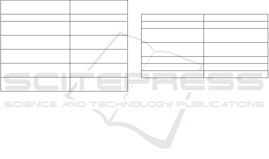
Table 3: Corresponding elements between scenario and
sequence diagram.
Scenario with SCEL Sequence diagram
with PlantUML
Title Title
Viewpoints (human type
noun)
Objects (actor)
Viewpoints (function type
noun)
Objects (Participant)
Event (data flow from A to
B)
Message passing
(from source to goal)
Event (actions to B) Action + object (from
agent to goal)
Event (actions by itself) Action + object (Self-
message)
The scenario title will be copied to the title of
sequence diagram in the transformation. Viewpoints
in a scenario can be classified into viewpoints of
human type and viewpoints of others. We transform
viewpoints of human type in a scenario into objects
of actor in a sequence diagram, while viewpoints of
non-human type are transformed into objects of
participant.
An event of data flow consists of source case,
goal case, object case, and instrument case. In the
transformation of a data flow event, noun of object
case corresponds to a message, noun of source case
corresponds to sender of the message, and noun of
goal case corresponds to receiver of the message.
In the transformation of an event whose action
has goal case, action and its object will be
transformed into a message, agent case noun can be
transformed into sender of the message, and goal
case noun will be transformed into receiver of the
message.
In the transformation of an event without goal
case, action and its object will be transformed into
self-message, and the agent case noun can be
transformed into sender/receiver of the message.
Most events in a scenario are sequential events,
but selective, iterative, or parallel events can be
described with SCEL. These time sequences can be
transformed using combined fragments of sequence
diagram as shown in Table 4.
The sequence of viewpoints in a scenario is used
for placing objects (actors and participants) in a
transformed sequence diagram. A user can change
the order of objects in the transformed diagram later.
In Table 2, we provided concepts and their case
structures for train ticket system. These concepts can
be classified into three categories, namely to say, (1)
DFLOW(data flow), (2) RET, SHOW, PAY (actions
with goal case), and (3) SELECT, RESERVE,
CHARGE, PRINT, VALIDATE (actions by itself.)
Table 4: Time sequences in scenario and corresponding
combined fragments of sequence diagram.
Time sequence Combined fragment
Selection (if…then…) Opt
Selection
(if…then…else…)
Alt
Iteration
(while do, do…until...)
Loop
AND-fork…join Par
OR-fork…join Par with guard condition
XOR-fork…join Par with guard condition
In Figure 1, verbs, “pass,” and “send”
correspond to data flow concept. Events with these
verbs are transformed into internal representation in
Table 5. Verbs “show,” and “retrieve” are actions
with goal case. Events with one of these verbs can
be transformed as shown in Table 6(a) and (b),
respectively. Verbs “select,” “reserve,” “charge,”
and “issue” are actions by itself. Events with one of
these verbs will be transformed in transformed as
shown in Table 7(a), (b), (c), (d), respectively.
In Table 5, instrument cases are omitted, because
the instrument case is optional and ignored in the
transformation. The events with DFLOW will be
transformed into messages passing whose senders
correspond to source case nouns, receivers
correspond to goal case nouns, and messages
correspond to object case nouns, respectively.
By applying our transformation method to the
internal representations, we can get a sequence
diagram with PlantUML shown in Figure 3.
“Hide footbox” in the fourth line in Figure 3 is
inserted in order to suppress to display objects at the
bottom of the diagram.
“If <condition> then <event>” statement in a
scenario can be transformed into combined fragment
of “opt <condition>; <transformed event>.” For
example, the eleventh event in Figure 1 will be
Transformation Method from Scenario to Sequence Diagram
139
transformed into “opt credit card is valid” and self-
message passing of “issue train ticket with seat
reservation” as shown in Figure 3.
Figure 4 shows a sequence diagram created by the
PlantUML viewer. Users can review transformed
sequence diagrams and correct them, if there exist
errors in the diagrams. When train seat reservation
system sends a successful message to clerk, the
system should send seat number and train information.
If these information should be added, sequence
diagrams and correct them, if there exist errors in the
diagrams. When train seat reservation system sends a
successful message to clerk, it should send seat
number and train information. If these information
should be added, user can modify the scenario and get
a revised sequence diagram by the transformation.
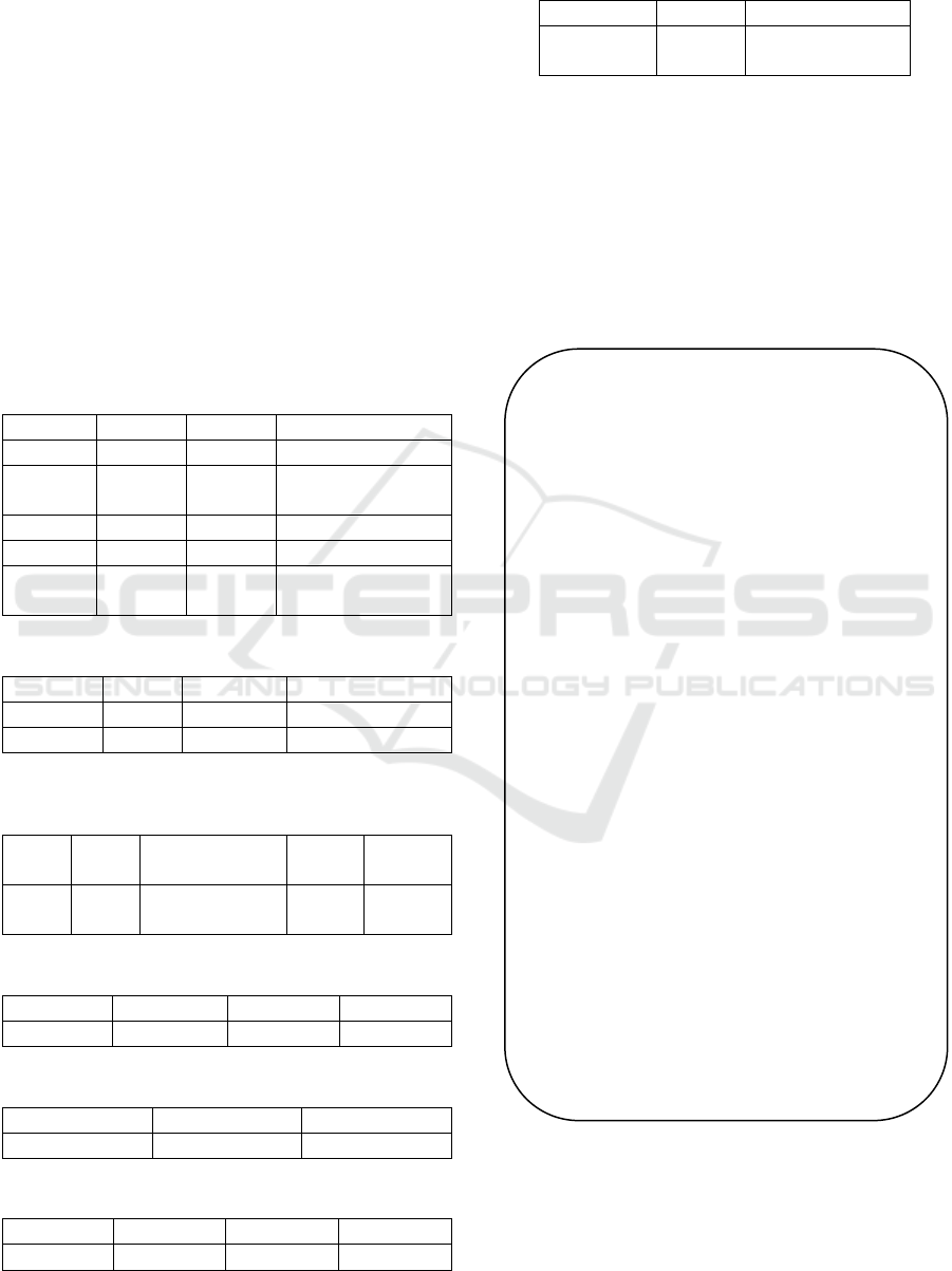
Table 5: Internal representations of events of DFLOW
(data flow).
event no. source goal object
1 customer clerk itinerary
6 clerk system request for seat
reservation
8 system clerk successful message
9 customer clerk credit card
12 clerk customer credit card and
ticket
Table 6(a): Internal representations of events of SHOW.
event no. agent goal object
3 system clerk list of empty seats
4 clerk customer list of empty seats
Table 6(b): Internal representation of event of RET
(retrieve).
event
no.
agent goal object key
2 clerk seat reservation
system
empty
seats
NOT
specified
Table 7(a): Internal representation of event of SELECT
event no. agent source object
5 customer list seat
Table 7(b): Internal representation of event of RESERVE.
event no. agent object
7 system seat
Table 7(c): Internal representation of event of CHARGE.
event no. agent object1 object2
10 clerk fare credit card
Table 7(d): Internal representation of event of
PRINT(issue).
event no. agent object
11 clerk train ticket with
seat reservation
In the transformation, activate statement of
objects should be inserted, just after the first
message passing of the object occurs. Similarly,
deactivate statement of objects should be inserted,
just after the last message passing of the object
occurs. For example, the first message passing of
“user1” and “user2” occurs in the ninth line in
Figure 3, so activate statement of these objects are
inserted after the message passing in the tenth and
eleventh lines, respectively.
@startuml{plantuml_train.png}
title purchase a train ticket with seat
reservation
hide footbox
actor customer as user1
actor clerk as user2
participant train seat reservation system as
object1
user1 -> user2: itinerary
activate user1
activate user2
user2 -> object1: retrieve empty seats
activate object1
object1 -> user2: show list of empty seats
user2 -> user1: show list of empty seats
user1 -> user1: select seat from list
user2 -> object1: request for seat reservation
object1 -> object1: reserve seat
object1 -> user2: successful message
deactivate object1
user1 -> user2: credit card
user2 -> user2: charge fare to credit card
opt credit card is valid
user2 -> user2: issue train ticket with seat
reservation
user2 -> user1: credit card and ticket
end
deactivate user1
deactivate user2
@enduml
Figure 3: Transformed sequence diagram from scenario in
Figure 1.
We have developed a prototype system based on
our transformation method with Java on Eclipse 4.4
Luna. This tool is a 3 man-month product.
KMIS 2018 - 10th International Conference on Knowledge Management and Information Sharing
140
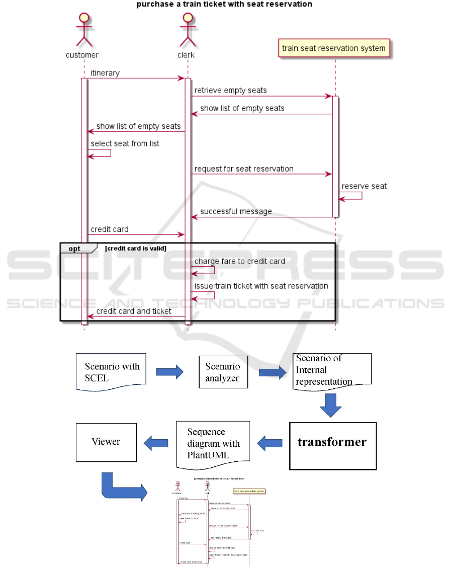
In Figure 5, we have already developed the
scenario analyser which transforms a scenario with
SCEL into internal representation. Our developed
prototype transforms a scenario of internal
representation into a sequence diagram with
PlantUML. Using PlantUML viewer, we can get a
sequence diagram as shown in Figure 4.
Figure 4: Transformed sequence diagram for purchasing a train ticket with seat reservation.
Figure 5: Transformer and related systems.
Transformation Method from Scenario to Sequence Diagram
141

5 DISCUSSION
We applied our transformation method to several
scenarios with SCEL such as hotel reservations,
modification of reserved train ticket, borrowing
books in library, and successfully got sequence
diagrams. Some problems are found in our
transformations as follows.
1) Objects are sometimes wrongly placed:
In the transformation, objects in sequence
diagram are placed according to the priority of
viewpoints in scenarios. For example, “viewpoints:
A, B, C” in a scenario means that the top priority
object is A, the second one is B, and the third one is
C. In the transformed sequence diagram, object A, B
and C are placed from left to right. If the first
message passing occurs from C to A, the direction of
this message is from right to left. We think the
direction of the first message should be from left to
right and the placement of object A and C should be
exchangeable.
2) Lifetime of objects may be wrong:
We insert “activate” statement of an object just
after it firstly appears and insert “deactivate”
statement just after it lastly appears. In this sense,
each object has just one “activate” and “deactivate”
statements. However, some objects should have a
few “activate” and “deactivate” statements.
3) Transformation from sequence diagrams with
PlantUML to scenarios with SCEL
The reverse transformation can be applied, but
some time sequences in sequence diagrams cannot
be represented in scenarios. The time sequences,
“break,” “critical,” and “par with guard condition”
of sequence diagram cannot be represented in
scenarios. Other time sequences of sequence
diagrams can be represented in scenarios as shown
in Table 4. In the reverse transformation, the
problem of wrong priority of viewpoints is still left
just like the first problem described above. Another
problem is lack of dictionaries of nouns and verbs
for scenarios. Verbs in scenario should be registered
in verb dictionary where its concept and case
structure should be specified. Nouns in scenario
should be registered in noun dictionary. Because
describer of sequence diagrams does not mind such
dictionaries, it is difficult to produce internal
representation in the reverse transformation.
It is difficult to automatically solve these
problems. As for the first problem, we manually
change the order of objects in the diagram with
PlantUML if necessary. As for the second problem,
we manually modify the “activate” and “deactivate”
statements in the sequence diagram.
As for the third problem, we consider that a
scenario with SCEL should be transformed into a
sequence diagram with PlantUML. Then, the
sequence diagram which may be modified slightly
will be reversely transformed into scenario. In such
transformations, noun and verb dictionaries of
scenarios can be provided and reverse
transformation can be successfully processed.
4) Scenarios may be wrongly specified
Our method transforms scenarios into sequence
diagram, but sometimes scenario may be wrongly
written. The correctness of scenarios (Achour, 1998)
is out of our research scope.
6 RELATED WORKS
There exist several researches for generating
sequence diagrams from scenarios or use case
descriptions.
Li, L. proposed a translation method of use cases
to sequence diagrams (Li, 2000). First, he
normalizes a use case description. Then, based on 25
verb patterns for English sentences in the Oxford
Advanced Learner’s Dictionary, he syntactically
classifies sentences into 13 types. Some types of
sentences are transformed into message passing in a
sequence diagram. The normalization and
classification are not automatic tasks, so his
approach is too hard to transform use case
descriptions into sequence diagrams, while our
approach enables to automatically transform
scenarios into sequence diagram.
Jali, N. et al. proposed a generation method of
sequence diagram from requirements written by
users (Jali, 2014). They extract classes, attributes,
methods, and relationships between classes from
requirements document based on template rules
using natural language processing technique.
Derived classes, methods and attributes are mapped
respectively with nouns, verbs and adjectives and
are then translated into UML sequence diagram
constructs. Their aim is to clear the system
behaviours and visualize them as sequence diagrams,
while our aim is to visualize interactions between
actors and system in a scenario as sequence
diagrams.
Sawprakhon, P. et al. proposed a model-driven
approach to transform UML class diagram and use
case description to sequence diagram (Sawprakhon,
2014). Since they adopt use case description written
with natural language, problems of the ambiguity of
natural language occur in analysis of use case
description. They use table of mapping
KMIS 2018 - 10th International Conference on Knowledge Management and Information Sharing
142

transformation from class diagram and use case
description to sequence diagram, but there exist the
ambiguity in the table, for example, different
elements of sequence diagram are generated from
same input items of class diagram and use case
description. Our approach does not provide such
ambiguous transformations.
Mason, P.A.J. et al. proposed a paraphrasing
method between use case descriptions (scenarios)
and sequence diagrams (Mason, 2009). They
classify events in scenarios into 6 types, that is to
say, Communication events (Service Request type,
Service Provision type, Information Request type,
and Information Provision type), Action type, and
Timing type. They give types of elements in
scenarios, such as “sender,” “receiver,” “message,”
“action,” and “timer” with a data dictionary. Using
the information in scenarios, sequence diagram can
be generated. It seems a labour to classify events and
add types to elements in scenarios, while our
approach does not require such a labour.
Segundo, L.M. et al. proposed a generation
system of sequence diagrams from use case
description (Segundo et al., 2007). They gave
several grammatical rules for use case descriptions,
such as “the use case description is built by simple
sentences separated by periods,” “the sentences must
begin with an article,” “the actor must include an
article at the beginning,” “the system will
considerate that the first noun found in the sentence
is the originator subject,” and so on. Since they use
simple sentences without complex time sequence,
generated sequence diagrams do not contain
combined fragments.
El-Attar, M. proposed a method for assembling
sequence diagrams from use case scenarios (El-Attar,
2011). In his approach, scenarios can be represented
as sequence diagrams. His approach is not a
transformation from scenarios to sequence diagram
but combining sequence diagrams (or scenarios) into
an integrated sequence diagram.
7 CONCLUSIONS
We proposed a transformation method from
scenarios written with SCEL to sequence diagrams.
We have developed a prototype system based on the
method. Through evaluation of the method and
prototype, we found our method and system
contributes to generate sequence diagrams from
scenarios efficiently and correctly.
Scenarios in SCEL can provide pre-conditions
and post-conditions, but we ignore them in this
paper. Using combined fragment, we will transform
these conditions in sequence diagram. This is left as
a future work.
ACKNOWLEDGEMENTS
We thank to Dr. H. Itoga and Mr. H. Nobuhira,
members of Software Engineering Laboratory,
Ritsumeikan University for their contributions to
this research. This research is partly supported by
Grant-in-Aid for Scientific Research, Japan Society
for the Promotion of Science, No.16K00112.
REFERENCES
Achour, C. B., 1998. Writing and correcting textual
scenarios for system design. In Proc. 9
th
International
Workshop on Database and Expert Systems
Applications, pp.166-170.
EL-Attar, M., 2011. A systematic approach to assemble
sequence diagrams from use case scenarios. In Proc.
3
rd
International Conference on Computer Research
and Development, pp.171-175.
Fillmore C. J., 1968. The Case for Case, Universals in
Linguistic Theory, ed. Bach & Harrms, Holy, Richard
and Winston Publishing, Chicago.
Jali, N., Grer, D., Hanna, P., 2014. Behavioral Model
Generation from Use Cases Based on Ontology
mapping and GRASP Patterns, In Proc. 26
th
SEKE2014, pp.324-329.
Li, L., 2000. Translating use cases to sequence diagrams.
In Proc. 15
th
IEEE ASE, pp.293-296.
Mason, P.A.J., Supsrisupachai, S., 2009. Paraphrasing use
case descriptions and Sequence Diagrams: An
approach with tool support. In Proc. 6
th
International
Conference on Electrical Engineering/Electronics,
Computer, Telecommunications and Information
Technology, pp.722-725.
Ohnishi, A., 1996. Software Requirements Specification
Database based on Requirements Frame Model, In
Proc. IEEE 2
nd
ICRE96, pp.221-228.
PlantUML, 2018. Language Reference Guide, http://
http://plantuml.com/PlantUML_Language_Reference_
Guide.pdf (Date of access, April 19, 2018)
Sawprakhon, P., Limpiyakom, Y., 2014. Model-driven
Approach to Constructing UML Sequence Diagram. In
Proc. ICISA, pp.1-4.
Segundo, L.M., Herrera, R.R., Herrera, Y.P., 2007. UML
Sequence Diagram Generator System from Use case
Description Using Natural Language. In Proc.
CERMA, pp.360-363.
Weidenhaupt, K., Pohl, K., Jarke, M., Haumer, P., 1998:
Scenarios in System Development: Current Practice,
IEEE Software, March, pp.34-45.
Zhang, H., Ohnishi, A., 2004. Transformation Method of
Scenarios from Different Viewpoints. In Proc. 11
th
APSEC 2004, pp.492-501.
Transformation Method from Scenario to Sequence Diagram
143
