
A Simplified MbUID Process to Generate Web Form-based UIs
Habib M. Fardoun
1
, Ricardo Tesoriero
2
, Gabriel Sebastian
2
and Nehme Safa
3
1
Ahlia University, Bahrain
2
Computing Systems Department, University of Castilla-La Mancha, Albacete, Spain
3
Instructional Education, Faculty of Education, Lebanese University, Beirut, Lebanon
Keywords:
Model-based user Interface Development, Model-driven Architectures, Unified Modeling Language, Model
Transformations.
Abstract:
Model-driven development technologies are employed to increase the productivity of software factories. The
traditional model-based development of UI requires high-quality human resources with specific skills about
concepts and technologies to build applications successfully. The poorly inclusion of model-driven develop-
ment technologies in computer science and engineering degree curricula in most universities leads to great
stress on junior developers that have to adopt this technology in a very short period of time to become pro-
ductive to the company. This is one of the challenges small companies and start-ups face when adopting this
technology. This paper proposes a simplified transformation process that simple UML class models as input
to produce Web form-based user interfaces. This process reduces the 2 meta-models and 2 transformation
languages required to develop this type of user interfaces using traditional approaches to only one meta-model
(UML) and one model-to-model-transformation language (ATL) to generate Web form-based user interfaces.
Even though this approach is not as powerful as traditional approaches are, it is good enough to introduce
junior developers to get in touch with the technology.
1 INTRODUCTION
The development of User Interfaces (UIs) is a costly
process along the whole product life cycle. Mod-
ern communication network infrastructures (e.g. 4G,
5G, etc.) provide users with high quality Internet ac-
cess almost anywhere in the world. Technology ad-
vances enable vendors to improve domestic devices
(e.g. fridges, washing machines, TVs, air condition-
ing systems, home automation devices, etc.) using
different sensors (e.g. humidity, temperature, pres-
sure, etc.) providing them with computing capabili-
ties to become smart when dealing with resources (i.e.
energy, water, etc.).
Moreover, these advances enable wearable com-
puting devices (e.g. smartwatches) to monitor user
physical activities (e.g. number of steps, running
time, etc.). They also enable smartphones to recom-
mend restaurants nearby or pay for the restaurant bill
using device capabilities (e.g. GPS and NFC). How-
ever, they are not the only sensors included in model
devices. They are also equipped with microphones,
high quality video and photo cameras, voice recog-
nition, accelerometers,digital compasses, GPS, NFC,
etc.
Consequently, new interaction techniques are
emerging to exploit this technology (i.e. movement-
based, vocal, gestural, etc.) resulting in additional re-
quirements (Petrasch, 2007). While these techniques
improve user interaction; they increase the complex-
ity of UI development. In addition, the market diver-
sity on software platforms supporting these technolo-
gies evolve quickly leading to re-writing the same UI
for different technologies.
A Model-driven Architecture (MDA) is a software
development framework standard that was originally
defined by the Object Management Group (OMG) in
2001 to propose an approach to deal with the con-
tinuous evolution of software technology for software
companies that re-write software applications to adapt
them to technology advances.
The solution is based on the definition of models
that capture the application functionality while avoid-
ing its implementation details. This representation
of the application is then bound to different software
platforms to generate the same application using dif-
ferent technologies.
The Cameleon Reference Framework CRF de-
fined in (Calvary et al., 2001) and extended in (Cal-
Fardoun, H., Tesoriero, R., Sebastian, G. and Safa, N.
A Simplified MbUID Process to Generate Web Form-based UIs.
DOI: 10.5220/0006943908010808
In Proceedings of the 13th International Conference on Software Technologies (ICSOFT 2018), pages 801-808
ISBN: 978-989-758-320-9
Copyright © 2018 by SCITEPRESS – Science and Technology Publications, Lda. All rights reserved
801

vary et al., 2002) and (Calvary et al., 2003) is a
widely accepted reference in the Human-Computer
Interaction (HCI) engineering community for struc-
turing and classifying model-based development pro-
cesses of UIs supporting multiple contexts of use.
The Interaction Flow Modeling Language
(IFML)(Brambilla and Fraternali, 2014) is the OMG
standard to model UIs inspired by the WebML
notation among many others.
Both approaches require non-trivial skills on
meta-modeling, model transformations, and program-
ming language in different paradigms. This level of
skills is not present on junior developers graduated
from universities that poorly include model-based de-
velopment on the computer science and engineering
degree curricula. And this is key issue in the lack of
adoption of model-based development technology in
small companies or start-ups.
To overcome this challenge, this article proposes
a simplified transformation process to generate basic
XHTML Web forms from plain UML Class models
using a single model-to-model transformation.
This process is described in the following sec-
tions. Next section introduces main concepts regard-
ing the MDA principles and their relation to the de-
velopment of UIs. Then, Section 3 presents the pro-
posed simplified transformation process to generate
Web form-based UIs from plain UML class mod-
els. Finally, Section 4 presents conclusions and future
works.
2 MDA PRINCIPLES AND USER
INTERFACES
The Model-driven Architecture (MDA)(OMG, 2014)
is a software development framework that was orig-
inally defined by the Object Management Group
(OMG) in 2001. It proposes an approach to deal with
the continuous evolution of software technology that
leads software companies to re-write applications to
adopt these technologies.
This approach consists in the separation of sys-
tem functionality specification from technology im-
plementation details.
Traditionally, MDAs define 3 layers of models:
The Computational Independent Model (CIM), the
Platform Independent Model (PIM), and the Platform
Specific Model (PSM).
The CIM provides the highest level of abstraction
point of view of a system. It describes what the sys-
tem is expected to do without exposing how to achieve
it. It specifies the system environment and require-
ments using the application domain specific vocabu-
lary. Usually, models defined in this layer of abstrac-
tion help developers to communicate with users by
defining a common language.
The PIM presents a lower level of abstraction
point of view of the system to be developed compared
to a CIM because it describes the system functional-
ity avoiding implementation details. Decoupling the
system functionality specification from the support-
ing platform enables developers to reuse the infor-
mation contained in a PIM in different software plat-
forms achieving the interoperability at design time.
The interoperability at design time leverages the soft-
ware abstraction and reuse enabling developers to de-
lay technology related decisions to the last minute
minimizing the impact of technology changes in the
development process.
The PSM presents a lower level of abstraction
point of view of the system compared to a PIM be-
cause it is the result of binding a PIM to a specific
software platform in order to obtain the complete
specification of a system for a concrete software plat-
form. As result of this software specification, devel-
opers obtain enough information to generate the ap-
plication source code, which is often referred as the
Implementation Specific Model (ISM) of the applica-
tion.
The MDA model specifications are written in Do-
main Specific Languages (DSL) defined by meta-
models capturing different application concerns. The
OMG defines the Meta-object Facility (MOF)(OMG,
2003) as a meta-meta-model to define meta-models
that define a DSL abstract syntax. The specification of
a meta-meta-model to build meta-models enables de-
velopers to create model transformations. The trans-
formation of MDA models laying in the same, or dif-
ferent layers of abstraction, is specified in terms of
transformation functions that can be automatically ap-
plied to a set of source models to generate target mod-
els.
Transformation functions are defined by sets of
transformation rules that map elements of source
meta-models into elements of target meta-models.
Thus, transformation functions can be applied to
source models conforming to source meta-models in
order to generate target models conforming target
meta-models. Model transformations can also gener-
ate source code because application source codes are
considered ISMs. Unlike model-to-model transfor-
mations (M2M), transformation generating ISMs are
also known as model-to-text transformations (M2T).
Capturing model transformation design decisions
in transformation functions enable developers to ap-
ply them to different models reducing the develop-
ment and maintenance costs.
IDEE 2018 - Special Session on Interaction Design in Educational Environments
802
2.1 Benefits of MDA
The following paragraphs expose the most relevant
benefits of adopting an MDA approach to develop
UIs.
First, the software platform independence through
the use of PIMs enables software specifications that
are more resistant to technology changes.
The use of meta-models to define DSLs facilitates
the communication among people from different do-
mains providing formal definition of vocabulary in
different domains as well as the translation among
them using model transformations. They also enables
developers to perform model validations before gen-
erating application source codes. Model validations
improve the application reliability reducing potential
errors in the implementation at early stages in the de-
velopment process.
The use of model transformations reduces the
gap between software implementation and documen-
tation because both, implementation and documenta-
tion, can be derived from models. Platform indepen-
dence, meta-model definitions and model transforma-
tions enable the interoperability at design time which
delays technology decisions to the last minute reduc-
ing its impact on the software development process.
The adoption of OMG standards, such as the XML
Model Interchange format (XMI) (OMG, 2005) to
manipulate models information facilitates the model
integration with third party tools and models.
The use of a multi-layer architecture representing
levels of abstraction and the definition of model trans-
formation enables developers to propagate changes
through the architecture until they reach the ISM
(source code) almost automatically reducing mainte-
nance costs. It also reduces the divergence among
different implementations also reducing maintenance
costs while improving software reliability.
2.2 The CAMELEON Reference
Framework
As we have mentioned in Section 1, different frame-
works have been conceptually defined to capture the
development process of UIs (Meixner et al., 2014).
An overview of the evolution of the Model-based
User Interface Development (MbUID) is presented in
(Meixner et al., 2011).
The CAMELEON Reference Framework (CRF)
(Calvary et al., 2003) presents an explicit set of mod-
els and meta-models jointly with their relationships to
represent the different perspectives of the UI taking
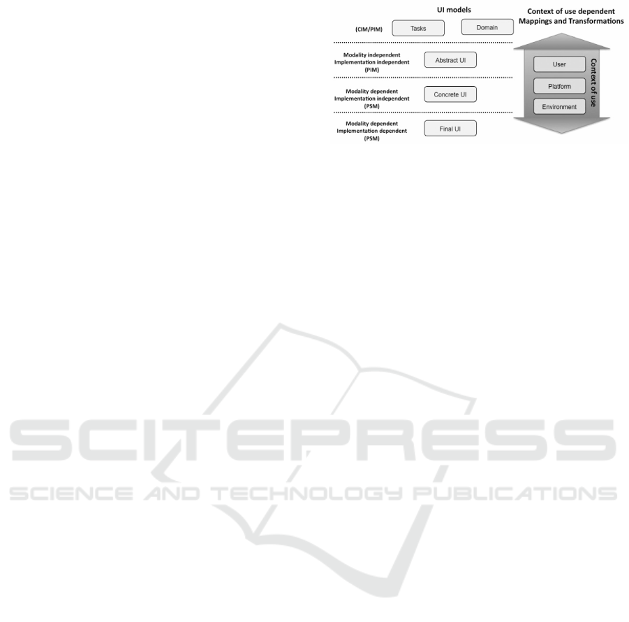
into account multiple contexts of use. The Figure 1
depicts a simplified version of the CRF mappings and
Figure 1: A simplified version of the CRF mappings and
transformations between levels of abstraction depending on
the context of use (Meixner et al., 2014).
transformations between levels of abstraction depend-
ing on the context of use (Meixner et al., 2014).
The Task and Domain models correspond to the
hierarchies of tasks that need to be performed on/with
domain objects (or domain concepts) in a specific
temporal logical order for achieving users’ goals dur-
ing the interaction with the user interface. Using
the wording of the OMG MDA specification(OMG,
2014) in the Software Engineering field, the Task
and Domain level is either a Computation Indepen-
dent Model (CIM) or a Platform Independent Model
(PIM).
The Abstract User Interface (AUI) model ex-
presses the user interface in terms of Abstract Inter-
action Units (AIU) or Abstract Interaction Objects
(AIOs) (Vanderdonckt and Bodart, 1993) as well as
the relationships among them. These AIUs are inde-
pendent of any implementation technology or modal-
ity (e.g., graphical, vocal, gestural). They can be
grouped to map logically connected tasks or domain
objects. From the MDA perspective, AUI models are
Platform Independent Models (PIM).
The Concrete User Interface (CUI) model ex-
presses the user interface in terms of Concrete In-
teraction Units (CIU) or Concrete Interaction Ob-
jects (CIOs) (Vanderdonckt and Bodart, 1993). These
CIUs are modality-dependent, though their imple-
mentation is technology independent. From the MDA
point of view, CUI models are Platform Specific Mod-
els (PSMs). The CUI concretely defines how the user
interface is perceived and manipulated by end users.
The Final User Interface (FUI) model expresses
the user interface in terms of implementation technol-
ogy dependent source code. A FUI can be represented
in any user interface programming language (e.g.,
Java UI toolkit) or mark-up language (e.g., HTML)
that can be compiled or interpreted. From the MDA
perspective, FUI models are Implementation Specific
Models (ISM).
A Simplified MbUID Process to Generate Web Form-based UIs
803

2.3 The Information Flow Modeling
Language
The Information Flow Modeling Language (IFML)
is a language specified by the OMG to describe in-
teraction flow models to represent front-end user-
application interactions.
The IFML specification(OMG, 2015a) consists
in the IFML meta-model described in MOF(OMG,
2003), the IFML UML Profile(OMG, 2015b), a vi-
sual syntax defined through the Diagram Definition
and the Diagram Interchange specifications, and the
IFML XMI(OMG, 2005) model exchange format.
The IFML defines extensions to support different
technologies. For instance, the extension presented
in (Brambilla et al., 2014) enables the specification of
Mobile Applications Front Ends.
The rest of this section presents a brief description
of IFML extracted from (Blanckaert, 2015).
The IFMLModel is the top-level container of all
the model elements. It contains the InteractionFlow-
Model, the DomainModel and can optionally contain
ViewPoints.
The DomainModel is a UML class diagram which
describes the content available to the interaction flow
model. The elements of the DomainModel can be ref-
erenced inside the InteractionFlowModel.
The ViewPoints are selections of elements of
the InteractionFlowModel that compose one specific
functional aspect of the application.
The InteractionFlowModel forms the core of an
InteractionFlowModel. Inside this model, the el-
ements of the DomainModel can be referenced by
means of ContentBindings.
The following paragraphs describe the Interac-
tionFlowModel components based on the IFML spec-
ification document(Brambilla and Fraternali, 2014).
The ViewContainer is a UI element which con-
tains other elements (i.e. other ViewContainers or
ViewComponents). It can group elements that can be
accessed by the user at the same time or grouping el-
ements which the user can only access alternatively.
The ViewComponent is a UI element that is con-
tained in a ViewContainer. It can present content to
the user and/or allows for interaction.
The ViewComponentPart is an element that can
only reside in a ViewComponent providing more in-
depth interaction details of a view component.
While an Event is the result of an interaction per-
formed by the user through the UI or by the applica-
tion itself; anAction is an operation performed by the
application behind the scenes. Actions are triggered
by events.
An InteractionFlow carries Parameters between
Problem
Model
1
=De f inition
??
Model
1
Model
2
= f
M2M
(Model
1
)
Model
2
//
. . .
//
Model
n−1
Model
n
= f
0
M2M
(Model
n−1
)
Model
n
Solution= f
M2T
(Model
n
)
??
Solution
Figure 2: MDA development process transformation chain.
elements in the IFML model, upon the occurrence of
an Event. The Parameters sent in the outgoing side
of the flow are used as input Parameters for the el-
ement at the incoming side of the flow. There are
two kinds of interaction flows: NavigationFlows and
DataFlows. While the DataFlows are only used to
carry parameters among model elements; the emph-
NavigationFlows also navigate the user to the element
at the arriving side of the flow.
A Parameter is a variable that can be passed
around by flows. It can be held by any Interac-
tionFlowModel element which can have in-coming or
out-going flows. A ParameterBinding is the associa-
tion of input and output parameters of a flow. And
a ParameterBindingGroup groups several Parame-
terBinding which are associated to the same flow.
An ActivationExpression is a Boolean expression,
possibly using Parameters, which enables or disables
an element of the InteractionFlowModel, depending
on whether it respectively evaluates either to true or
false. On the other hand, an InteractionFlowExpres-
sion is an expression that selects the interaction flows
that have to be followed.
A Module is an element that abstracts a piece of an
interaction flow model to improve model readability,
reusability and maintainability.
Finally, a Port is an element belonging to a mod-
ule, which allows to input or output interaction flows
and Parameters to and from the Module using an In-
putPort or an OutputPort respectively.
2.4 Analyzing the MbUID Process
The Fig. 2 summarizes the traditional MDA develop-
ment process where developers start with the defini-
tion of a PIM (e.g. Model
1
) representing a Problem.
Then, they apply in turn model-to-model (M2M)
transformation functions (e.g. f
M2M
, f
0
M2M
, etc.)
to obtain refined models of the application (e.g.
Model
2
,. . . ,Model
n−1
) building a transformation
chain until they reach a PSM (e.g. Model
n
) that is
transformed into an ISM or the Solution source code
IDEE 2018 - Special Session on Interaction Design in Educational Environments
804

CRF
IFML
PROP
PIM
AUI
M2M
IFML
Profile
M2M
UML
M2M
PSM CUI
M2T
Marked
IFML
M2T
TagML
M2T
ISM
FUI
Source Source
Figure 3: Transformation process comparison.
using a model-to-text (M2T) transformation function
( f
M2T
). Transitions between models are usually en-
riched with mark models(Mellor, 2004) to add extra
information to models while keeping model reusabil-
ity levels. The application of this process in a MbUID
scenario where the CRF and IFML approaches are
compared can be seen on the second and third column
of the Fig. 3.
In a CRF modeling scenario, an AUI model plays
the role of a PIM and a CUI (or Marked CUI) plays
the role of PSM. On the other hand, in an IFML mod-
eling scenario, a model following the IFML Profile
model plays the role of PIM and a Marked IFML Pro-
file model plays the role of PSM.
Both approaches are very powerful due to
reusability, flexibility, extensibility and maintainabil-
ity; however, there is a set of skills that are re-
quired to generate even simple Web form-based UIs
in XHTML. For instance, developers have to learn a
PIM meta-model (the AUI or the IFML Profile). They
also have to learn how to use marking models in or-
der to generate PSMs (e.g. Marked CUI or Marked
IFML Profile) using a M2M transformation language
that they have to learn too. Finally, they have to learn
a M2T transformation language to generate the appli-
cation source code.
Therefore, junior developers have to learn at least
2 meta-models and 2 transformation model languages
to generate even simple Web form-based UIs using
any approach.
As we have mentioned, it is an important issue
for junior developers graduated from universities that
include the model-based development subject in the
academic curricula of computing science and engi-
neering degrees as an elective subject, or do not in-
clude it at all. Consequently, these developers lack the
fundamental concepts about meta-modeling, model
transformations, and so on. These concepts are not
easy to acquire due to the following reasons:
The first reason is the abstraction gap between
the model and meta-model concepts no matter the
mechanism used to create them (MOF or UML Pro-
files). The second reason is the number of transfor-
mation languages following different programming
paradigms developers have to learn to define model
transformations. While M2T transformation lan-
guages usually follow an archetype-based program-
ming paradigm (e.g. Acceleo(Eclipse Foundation,
2016a) ); M2M transformation paradigms follow a
declarative programming paradigm (e.g. ATL(Eclipse
Foundation, 2016b) ). These reasons increase the
stress of junior developers because they have to ac-
quire lots of skills in a short period of time to become
productive for the company. Consequently, it discour-
ages small companies and start-ups the adoption of
model-based UI development technologies.
To overcome this situation we propose the simpli-
fication of the development process presented in Sec-
tion 3 to generate simple Web form-based UIs.
3 THE DEVELOPMENT
PROCESS SIMPLIFICATION
This section proposes a simplification of the develop-
ment process when generating Web form-based UIs .
The fourth column of the Fig. 3 depicts this approach
where developers start building a UML class model
representing the application domain model. This
model also plays the role of PIM of the UI; therefore,
developers use this model as the input model M2M
transformation that generates the PSM of the UI. This
PSM conforms to the TagML meta-model which cap-
tures the characteristics of XML documents. Models
conforming this meta-model are used to generate the
XHTML source code of Web form-based UIs using a
M2T transformation.
From the technological perspective, developers
create UML class models using any tool that complies
to the UML specification(OMG, 2015b) defined by
the OMG standards; for instance, Papyrus. Then, they
apply a M2M transformation function to generate the
PSM conforming the TagML meta-model described
in (Tesoriero, 2017). Finally, they apply the M2T
transformation function described in Section 3 using
the TagML PSM to generate the XML files defining
the Web form-based documents in XHTML.
The UML class models are familiar to junior de-
velopers because they are included as part of most
computing science and engineering degree curricula.
Besides, the CRF and the IFML approaches use UML
class models to represent application domain model
concepts; therefore, developers have experience on
class modeling in UML not requiring the study on an
extra PIM meta-model. Regarding the M2M transfor-
mation, this proposal defines ae M2M transformation
to generate TagML models representing Web form-
A Simplified MbUID Process to Generate Web Form-based UIs
805

based UIs as XHTML documents. Therefore, de-
velopers need to study a M2M transformation lan-
guage and the TagML meta-model only if the M2M
transformation requires an extension. The proposed
PSM meta-model to generate Web form-based UIs is
TagML is presented (Tesoriero, 2017). This meta-
model enables the definition of models representing
XML documents. These representations are used as
input models of the M2T transformation exposed in
Section 3 that generates files containing XML docu-
ments. Thus, developers do not require the study of a
M2T transformation language to generate XML based
UIs (e.g. XHTML Web form-based UIs).
3.1 The UML Class to TagML Model
Transformation
The definition of the M2M transformation function in
ATL(Eclipse Foundation, 2016b) that converts UML
class models into TagML models representing Web
forms-based UIs XML documents. The ModelRule
generates a TagMLModel instance for each instance
of Model instance. It associates the collection of
the Web form-based UI XML docoments a Model
instance represents. The ClassRule generates a
TagMLDocument instance for each instance of Class
describing a Web page containing two sections.
The first section defines a table to access and edit
all Class instances the TagMLDocument instance
represents. It enables users to access the information
of single instances through the second section which
defines a form to edit the set of properties of a
Class instance. These sections are created using the
CreateTable and CreateForm lazy rules which collect
the information generated by the PropertyRule
matched sub-rules. The PropertyRule sub-rules
are structured to generate controls depending on
Propertys state. The PropertyRule defined two
sub-types of rules: The PropertyNotAssociationRule
and the PropertyAssociationRule rules. While the
first one generates controls to manipulate attributes;
the second one generates controls to manipulate
associations. The guards for each rule in OCL are
property.association.oclIsUndefined() and
not property.association.oclIsUndefined()
respectively. The PropertyNotAssociationRule rules
create fields in the document to manipulate Class
attributes. It defines two sub-rules: The Proper-
tyNotAssociationSingleRule and the PropertyNotAs-
sociationManyRule rules that are guarded by the
property.upper = 1; and the property.upper
> 1; OCL expressions respectively. The Prop-
ertyNotAssociationSingleRule rules generate form
input fields for single-valued instances. Different
sub-rules (i.e. PropertyNotAssociationSingleTex-
tRule, PropertyNotAssociationSingleIntegerRule,
PropertyNotAssociationSingleCurrencyRule, and
PropertyNotAssociationSingleDateRule) are de-
fined for each type of Property (i.e. Text, Integer,
Currency, and Date). The PropertyNotAssocia-
tionSingleMiscRule rule defines a TEXT input field
for the remining types. The PropertyNotAssocia-
tionManyRule rules generate form input fields, lists
(including a SELECT tag with nested OPTION tags),
and controls (i.e. Add and Remove buttons) to ma-
nipulate multi-valued Property instances. Different
sub-rules (i.e. emphPropertyNotAssociationMany-
TextRule, PropertyNotAssociationManyIntegerRule,
PropertyNotAssociationManyCurrencyRule, and
PropertyNotAssociationManyDateRule) are de-
fined for each type of Property (i.e. Text, Integer,
Currency, and Date). The PropertyNotAssociation-
ManyMiscRule rule define a TEXT input field for
the remining types. The PropertyAssociationRule
rules provide controls to manipulate target Class
instance properties. It defines two sub-rules: The
PropertyAssociationNotCompositeRule and the
PropertyAssociationCompositeRule rules which
are guarded by not umlProperty.isComposite
and umlProperty.isComposite OCL expressions
respectively. The PropertyAssociationNotCompos-
iteRule rule defines two sub-rules: the PropertyAsso-
ciationNotCompositeSingleRule (i.e. in OCL) and the
PropertyAssociationNotCompositeManyRule to deal
Property cardinality. While single-valued Property
instances are guarded by the property.upper =
1; OCL expression; multi-valued emphProperty
instances are guarded by the property.upper >
1; OCL expression. The PropertyAssociationNot-
CompositeSingleRule rule generates a combo-box
(a SELECT tag with nested OPTION tags) to select
an instance of the target Property instance. The
PropertyAssociationNotCompositeManyRule rule
generates two lists (including a SELECT tag with
nested OPTION tags) and controls to add and remove
elements (i.e. BUTTON tags). The PropertyAsso-
ciationCompositeRule rule defines two sub-rules:
the PropertyAssociationCompositeSingleRule and
the PropertyAssociationCompositeManyRule to
deal with on the Property cardinality. While
single-valued Property instances are guarded by the
property.upper = 1; OCL expression; multi-
valued emphProperty instances are guarded by the
property.upper > 1; OCL expression. The Prop-
ertyAssociationCompositeSingleRule rule generates
controls (including a BUTTON tag) to access the
section to edit a single Class instance. On the other
hand, the PropertyAssociationCompositeManyRule
IDEE 2018 - Special Session on Interaction Design in Educational Environments
806
rule generates controls (including a BUTTON tag) to
access the section that provides access to the list of
Class instances.
3.2 The TagML to XML Model
Transformation
The TagML to XML M2T transformation con-
sists in 9 simple rules that are defined in Ac-
celeo(Eclipse Foundation, 2016a). The gener-
ateElement(aTagMLModel : TagMLModel) iter-
ates over all TagMLDocument instances calling
the generate(aTagMLDocument : TagMLDocument)
rule to generate all model files. The gener-
ate(aTagMLDocument : TagMLDocument) gener-
ates a file for each TagMLDocument instance. The
file name corresponds to the TagMLDocument in-
stance name property. This rule iterates over the
collection of TagMLContent content collection call-
ing the generate(aTagMLContent : TagMLContent)
rule to generate document contents. The gener-
ate(aTagMLContent : TagMLContent) rule is overrid-
den by 4 rules. The generate(aTagMLText : TagML-
Text) rule generates plain text defined by the text prop-
erty of TagMLText. The generate(aTagMLComment
: TagMLComment) rule generates an XML comment
with the content defined by the text property of a
TagMLComment. The remaining two rules gener-
ate XML tags. The generate(aTagMLTag : TagML-
Tag) guarded by the self.contents->notEmpty()
OCL expression generates tags that contains other
tags (i.e. nested tags). On the other hand, gen-
erate(aTagMLTag : TagMLTag) guarded by the
self.contents->isEmpty() OCL expression gen-
erates tags that doest not contain any other tags
(i.e. empty tags). Both rules also generate XML
attributes iterating over the attributes collec-
tion and calling the generate(aTagMLAttribute :
TagMLAttribute) rule.
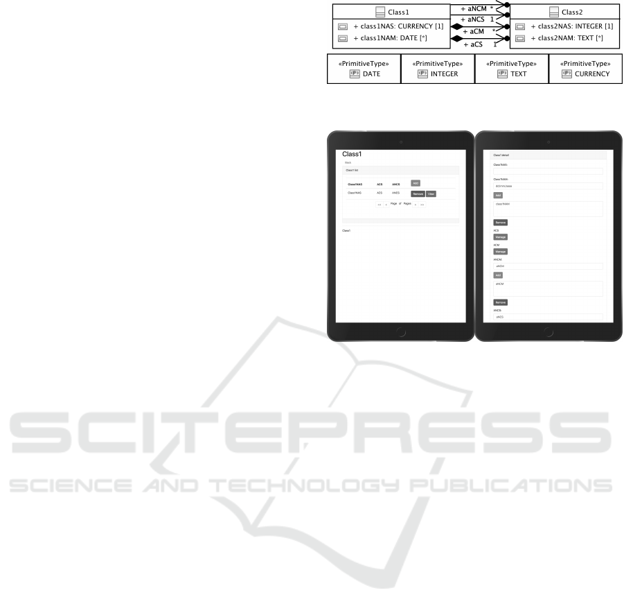
The Fig. 4 illustrates the proposed simplified
transformation process which defines the most rel-
evant transformation patterns between Class1 and
Class2 based on the following class property
characteristics: non-association (single-valued and
multi-valued), association composition (single-valued
and multi-valued) and association not composition
(single-valued and multi-valued).
The results of applying the M2M transformation
and the M2M transformation to the model depicted in
Fig. 4 are two files (class1.html and class2.html)
located in the tagml-concepts folder. The Fig. 5
(left) and Fig. 5 (right) show the table and form
UI sections defined in the class1.html file. On
the other hand, the Fig. 6 (left) and Fig. 6 (right)
Figure 4: Model representing different transformation pat-
terns.
Figure 5: Generated Class1 UI.
show the table and form UI sections defined in the
class2.html file. The UI depicted in Fig. 5 (left)
defines a table containing the fields representing the
single-valued properties to identify Class1 instances.
It also provides controls to access Class1 instances
through the Add and View buttons. On the other hand,
the UI depicted in Fig. 5 (right) defines a form to edit
Class1 properties. The Class1NAS input field enables
users to edit the class1NAS non-association single-
valued attribute. The Class1NAM input field, list,
Add and Remove buttons enable users to add/remove
the elements to/from the class1NAM non-association
multi-valued attribute. The ACS Manage button nav-
igates to the Class2 form UI (see on the right of
Fig. 6) to edit the properties of the aCS single-valued
composition association. The ACM Manage button
navigates to the Class2 table UI (see on the left of
Fig. 6) to add/remove the elements to/from the aCM
multi-valued composition association. The ANCM
combo-box, list, Add and Remove buttons enable
users to add/remove the instances of Class2 to/from
the aNCM non-composition multi-valued association.
The ANCS combo-box enables users to set the in-
stance of Class2 to the aNCS non-composition single-
valued association.
A Simplified MbUID Process to Generate Web Form-based UIs
807
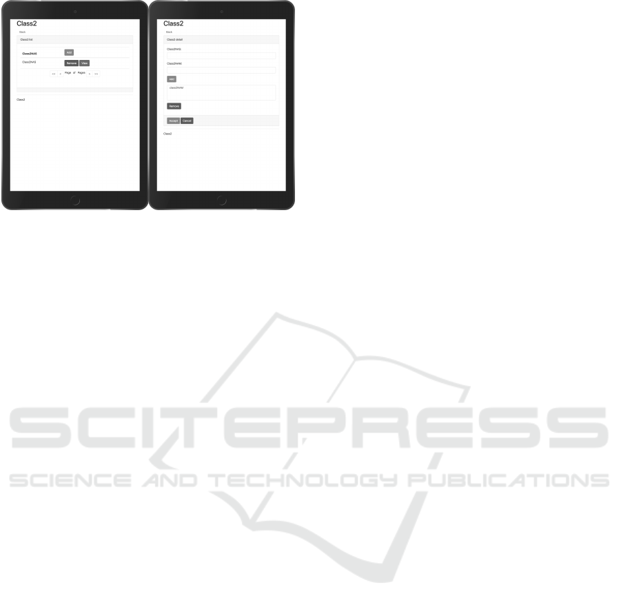
Figure 6: Generated Class2 UI.
4 CONCLUSIONS
Due to the lack of the inclusion of basic concepts
regarding the model-based development in computer
science and engineering degree curricula, junior de-
velopers are overwhelmed with new concepts and
technologies when dealing with them in the profes-
sional field.
To reduce this gap, we proposed a simplified trans-
formation process for junior developers that turns
plain UML Class models into HTML Web forms us-
ing a single model-to-model transformation.
The UML is a really popular language in the
academic environment and it is part of most com-
puter science and engineering degrees. Both, the
CRF and the IFML use UML class models to rep-
resent application domain model concepts; therefore,
developers should have experience on class model-
ing in UML. Thus, developers only have to learn
the subset of UML meta-model concepts related to
UML class models, a model-to-model transformation
language (ATL(Eclipse Foundation, 2016b)) to cus-
tomize transformations, and the simple TagML; in-
stead of learning a language for the PIM (AUI or
IFML profile), a language for the PSM (CUI or Marks
for IFML profile), a M2M transformation language
(e.g. ATL) and a M2T transformation language (e.g.
Acceleo(Eclipse Foundation, 2016a) ).
Even though this approach is not as powerful as
traditional approaches, it is good enough to introduce
junior developers to get in touch with the technology.
As future works, we plan to conduct a user evaluation
to determine the learning curve in model-based devel-
opment of UIs when using this approach as a starting
point. We also plan to introduce new rules to cover
other UML class model patterns in order to generate
richer UIs.
REFERENCES
Blanckaert, J. (2015). Integrating the Interaction Flow
Modelling Language (IFML) into the Web Semantics
Design Method (WSDM). Master Thesis.
Brambilla, M. and Fraternali, P. (2014). Interaction Flow
Modeling Language. Elsevier, 1st edition edition.
Brambilla, M., Mauri, A., and Umuhoza, E. (2014). Extend-
ing the interaction flow modeling language (IFML)
for model driven development of mobile applications
front end. In Mobile Web Information Systems, pages
176–191. Springer International Publishing.
Calvary, G., Coutaz, J., and Thevenin, D. (2001). A unify-
ing reference framework for the development of plas-
tic user interfaces. LNCS, 2254:173–192.
Calvary, G., Coutaz, J., Thevenin, D., Limbourg, Q., Bouil-
lon, L., and Vanderdonckt, J. (2003). A unifying ref-
erence framework for multi-target user interfaces. In-
teracting with Computers, 15(3):289–308.
Calvary, G., Coutaz, J., Thevenin, D., Limbourg, Q., Sou-
chon, N., Bouillon, L., Florins, M., and Vanderdonckt,
J. (2002). Plasticity of user interfaces: A revised ref-
erence framework. In Proceedings of the First Inter-
national Workshop on Task Models and Diagrams for
User Interface Design. 18-19 July 2002, Bucharest,
Romania, pages 127–134.
Eclipse Foundation (2016a). Acceleo. https://eclipse.
org/acceleo/.
Eclipse Foundation (2016b). The Atlas Transformation
Language. https://eclipse.org/atl/.
Meixner, G., Calvary, G., and Coutaz, J. (2014). Introduc-
tion to model-based user interfaces.
Meixner, G., Patern
`
o, F., and Vanderdonckt, J. (2011). Past,
present, and future of model-based user interface de-
velopment. I-COM, 10(3):2–11.
Mellor, S. (2004). MDA Distilled, Principles of Model
Driven Architecture. Addison-Wesley Professional.
OMG (2003). Meta Object Facility (MOF) 2.0 core specifi-
cation. https://www.omg.org/spec/MOF.
OMG (2005). XML Metadata Interchange (XMI) Specifi-
cation version 2.5.1. https://www.omg.org/spec/
XMI.
OMG (2014). Model Driven Architecture (mda) mda guide
rev. 2.0. https://www.omg.org/mda/.
OMG (2015a). Interaction Flow Modeling Language ver-
sion 1.0. https://www.omg.org/spec/IFML/1.0/.
OMG (2015b). OMG Unified Modeling Language TM
(omg uml) version 2.5. https://www.omg.org/
spec/UML/2.5/.
Petrasch, R. (2007). Model based user interface de-
sign: Model driven architecture und HCI patterns TM.
Softwaretechnik-Trends, 27(3).
Tesoriero, R. (2017). TagML: Un lenguaje para generar
documentos basados en etiquetas. Technical report,
University of Castilla-La Mancha. .
Vanderdonckt, J. and Bodart, F. (1993). Encapsulating
knowledge for intelligent automatic interaction ob-
jects selection. pages 424–429.
IDEE 2018 - Special Session on Interaction Design in Educational Environments
808
