
Energy Analysis and Exergy Analysis of a New Type Solar Air
Conditioning System
Xi Bai
School of Aeronautic Science and Engineering, Beihang University, XueYuan Road, Beijing, China
Baixi_buaa@163.com
Keywords: Solar air conditioning, Heat pump, Energy Analysis, Exergy Analysis.
Abstract: This paper presents a novel type of solar air conditioning system. The steady thermodynamic analysis model
and exergy analysis model are given to analyse the performance of the novel system. The energy analysis and
exergy analysis are carried out through detailed calculation. The exergy system analysis shows that the highest
exergy destruction occurs in condensation-generation and condensation 2, which can be reduced with
parameter optimization. A range of operating conditions are selected and simulated for the novel solar air
conditioning system by changing the corresponding parameters while keeping other parameters consistent
with the design conditions. Compared with the original solar air conditioning system, the novel solar air
conditioning system possesses the advantages of low requirements for the performance of solar collectors and
smaller area of solar collectors. The novel system is also less affected by weather conditions.
1 INTRODUCTION
To reduce environment pollution and energy
conservation, solar air conditioning researches are of
great significance. Solar energy is a kind of clean and
renewable energy. Since the refrigerating demand and
the supply of solar radiation are almost in phase with
each other, the solar air conditioning system is
appealing to many researchers (Hwang, Y.,
Radermacher, R., Alili, A. and Kubo, I. 2008; Sekret,
R. and Turski, M. 2012 ). The most common kind of
solar air conditioning system, which can be seen as
the original system, is composed of solar collectors
and the single effect LiBr–H
2
O absorption chiller.
However, the original system is confronted with
many problems in practical operation, including
crucial problems like intermittency and instability. In
order to solve the existing problems, a number of
relevant studies are carried out by many researchers.
Xu presented a new solar powered absorption
refrigeration system with advanced energy storage
technology. The energy collected from the solar
radiation was transformed into the chemical potential
of the working fluid and stored in order to solve the
problem of the unconformity between solar radiation
and cooling demand (Xu, S., Huang, X. and Du, R.
2011). Lass-Seyoum tested a similar closed thermo-
chemical heat storage system. This method offers
several advantages including the possibility of long-
term storage with minimal thermal losses and a high-
energy storage density compared with sensible and
latent thermal storage principles (Lass-Seyoum, A.,
Blicker, M., Borozdenko, D., Friedrich, T. and
Langhof, T. 2012).
Ahachad combined an absorption heat pump
system and an absorption refrigeration system to form
a two-stage vapor absorption system. And the tests
conducted in Rabat (Morocco) showed that the
system can be operated at lower heat source
temperatures by using flat-plate collectors (Ahachad,
M., Charia, M. and Bernatchou, A. 1993). Jain
proposed a cascaded vapour compression–absorption
system (CVCAS) which consists of a vapour
compression refrigeration system (VCRS) coupled
with single effect vapour absorption refrigeration
system (VARS). Based on first and second laws, a
comparative performance analysis of CVCAS and an
independent VCRS has been carried out (Jain, V.,
Kachhwaha, S. and Sachdeva, G. 2013).
Prasartkaew studied the performance of a
renewable energy (solar–biomass) based on single
effect LiBr–H
2
O absorption chiller. The chiller and
overall system coefficient of performances were
found to be 0.7 and 0.55 respectively and the biomass
(charcoal) consumption for 24h operation was
24.44kg/day (Prasartkaew, B. and Kumar, S. 2010).
Y.L. Liu presented the performance prediction of a
solar/gas driving double effect LiBr-H
2
O absorption
Bai, X.
Energy Analysis and Exergy Analysis of a New Type Solar Air Conditioning System.
In 3rd International Conference on Electromechanical Control Technology and Transportation (ICECTT 2018), pages 33-40
ISBN: 978-989-758-312-4
Copyright © 2018 by SCITEPRESS – Science and Technology Publications, Lda. All rights reserved
33

system. Its high-pressure generator is driven by
natural gas. Simulation results illustrated that such
kind of system is feasible and economical (Liu, Y.
and Wang, R. 2004). Apart from gas boiler, there also
exist electric heaters and oil boilers used as auxiliary
equipment. For a number of absorption systems that
employed heat recovery in the industrial sector or in
large residential buildings have the auxiliary of gas or
oil, as described in the experimental studies (Pérez de
Viñaspre, M., Bourouis, M., Coronas, A., Garcı
́
a, A.,
Soto, V. and Pinazo, J. 2004; Sumathy, K., Huang, Z.
and Li, Z. 2002; Ali, A., Noeres, P. and Pollerberg, C.
2008).
In order to reduce the influences of the weather
conditions on the solar air conditioning system, a
novel solar air conditioning system with heat pump as
auxiliary equipment is proposed in this paper.
Compared with the auxiliary of gas/oil, the novel
system needs fewer additional equipment like boilers
and gas/oil tanks. The energy analysis and exergy
analysis of the novel system are carried out through
detailed calculation to get a better view of the system.
A comparison between the novel system and the
original system is also considered in this study.
2 SYSTEM DESCRIPTION
Fig. 1 illustrates the main components of the novel
solar air conditioning system. The system is mainly
composed of three subsystems: solar collecting (SC)
subsystem, heat pump (HP) subsystem and
absorption refrigeration (AR) subsystem. The SC
subsystem, using water as working medium, consists
of flat-plate solar collectors and a water pump. The
HP subsystem , using R134a as working medium,
mainly consists of evaporator 1, condensation 1,
expansion valve 1 and compressor. The AR
subsystem mainly consists of generator, absorber,
evaporator 2, condensation 2, expansion valve 2, a
heat exchanger and a solution pump,using lithium
bromide solution as working fluid pair. For reducing
the component number of the system, condensation 1
and generation can be integrated as one compact
component, condensation-generation, which can also
help the heat source keep stable.
Figure 1: The schematic diagram of a new type of solar air
conditioning system.
The working flow of the system is shown as
follows.
(1)The SC subsystem receives low-grade energy
through gathering solar radiation to warm the
working medium water. Then, the low-grade energy
was transferred to HP subsystem in evaporator 1.
(2)In the HP subsystem, the working medium
R134a is cycled among the components, transforming
the energy from evaporator 1 to condensation-
generation, which also means that the low-grade
energy is transformed to high-grade energy to ensure
the normal operation of AR subsystem.
(3)In the AR subsystem, the high-grade energy
from the HP subsystem is used to produce chilled
water in evaporation 2 for cooling application.
3 MODELS OF
THERMODYNAMIC ANALYSIS
In order to simplify the calculation of the
performance analysis, a set of assumptions are made
as follows.
(1) The analysis is made under steady conditions.
(2) The pressure losses in the pipelines and all
components are negligible.
(3) The heat transfer between all components and
surroundings is ignored.
(4) The energy consumed by the solution pump
and the water pump is negligible.
(5) The lithium bromide aqueous solution at the
outlet of absorber and generator is assumed to be in
equilibrium at their respective temperatures and
pressures.
(6) The refrigerant (water) at the outlet of
evaporator 1, condenser 1, evaporator 2 and
condenser 2 is saturated.
ICECTT 2018 - 3rd International Conference on Electromechanical Control Technology and Transportation
34

The efficiency expression of the solar collectors is
determined as indicated in Eq. (1). The optical
efficiency is 0.67 and the linear coefficient of thermal
losses is 5.52 W/℃/m
2
0.67 5.52
SC am
SC
SC
TT
I
(1)
where I
SC
is the solar intensity. The terms T
am
and T
SC
are the environment temperature and the average
temperature of working medium in collectors
separately.
The governing equations of mass conservation
and species conservation can be expressed as
0
io
mm
(2)
- =0
io
mx mx
(3)
where m is the mass flow rate and x is mass
concentration of LiBr in the solution.
The energy balance of each component based on
the first thermodynamic for a steady state can be
expressed as
- + 0
o
i o i
mh mh Q Q W
(4)
The exergy with reference to the environment can
be expressed as
0 0 0
e h h T s s
(5)
where h
0
and s
0
are evaluated at the reference
environment.
Exergy destruction of a control volume based on
the second thermodynamic can be calculated as
follow,
00
- 1 1
x i o o
i
io
E m e m e W
TT
QQ
TT
(6)
The cooling COP of the novel solar air
conditioning system can be defined as follow,
12 10AR AR AR
SYS
HP
m h h
COP
W
(7)
where W
HP
is the electric energy consumption of the
HP subsystem; m
AR
is the mass flow rate of refrigerant
vapour (water) of the AR subsystem.
The exergy efficiency of the novel solar air
conditioning system can be defined as
, 2 , 1
,2 ,1
CW x CW x CW
SYS
SC x SC x SC HP
m e e
ECOP
m e e W
(8)
where m
SC
is the mass flow rate of SC subsystem; m
CW
is the mass flow rate of the chilled water in evaporator
2.
Based on the properties of the water, R134a and
lithium bromide aqueous solution, the equations
above are determined to describe the mass transfer,
heat transfer and exergy destruction in every
component.
4 RESULTS ANALYSIS UNDER
DESIGN CONDITIONS
To analyse the performance of system quantitatively,
the design operating conditions are selected as
follows.
(1) Flat-plate collectors are selected, with an area
of 100 m
2
. The inlet temperature of the collectors is
maintained at T
1SC
=70 ℃ by using variable speed
pump to regulate water mass flow rate.
(2) The condensation temperature of HP
subsystem is maintained at T
C,HP
=90 ℃, which means
the heat source temperature of AR subsystem T
HS,AR
=
T
C,HP
=90 ℃.
(3) The efficiency of the compressor is 0.63.
(4) The condensation temperature of AR
subsystem is maintained at T
C,AR
=40 ℃, the
evaporation temperature of AR subsystem is
maintained at T
E,AR
= 10 ℃.
(5) The inlet temperature of cooling water is
assumed at T
W0
=30 ℃. The outlet temperature of
cooling water to condensation 2 and absorber is
assumed at T
WC
=T
WA
=T
W0
+3 ℃.
(6) The inlet temperature and outlet temperature
of the chilled water in evaporator 2 are respectively
maintained at T
CW1
=17 ℃, T
CW2
=13 ℃.
(7) The heat exchanger effectiveness is 0.7.
Energy Analysis and Exergy Analysis of a New Type Solar Air Conditioning System
35

Table 1: Thermodynamic properties of each point in the system.
Point
temperature
pressure
concentration
specific
enthalpy
specific
entropy
mass flow rate
℃
kPa
wt%
kJ/kg
kJ/(kg·K)
kg/s
1SC
70.00
-
-
293.02
0.96
0.6
2SC
85.58
-
-
358.38
1.14
0.6
3SC
85.58
-
-
358.38
1.14
0.6
1HP
72.79
2252.2
-
428.93
1.69
0.456
2HP
95.56
3244.2
-
438.97
1.70
0.456
3HP
90.00
3244.2
-
342.93
1.44
0.456
4HP
72.79
2252.2
-
342.93
1.45
0.456
1AR
36.00
-
52.62
79.28
0.24
0.459
2AR
36.00
-
52.62
79.28
0.24
0.167
3AR
63.34
-
52.62
137.19
0.42
0.167
4AR
69.86
-
52.62
151.23
0.46
-
5AR
80.00
-
57.68
184.89
0.47
0.152
6AR
48.13
-
57.68
121.42
0.28
0.152
7AR
48.13
-
57.68
121.42
0.28
0.152
8AR
40.67
-
54.35
93.71
0.25
0.444
9AR
74.93
7.38
-
2640.13
8.46
0.015
10AR
40.00
7.38
-
167.54
0.57
0.015
11AR
10.00
1.23
-
167.54
0.59
0.015
12AR
10.00
1.23
-
2519.23
8.90
0.015
Table 2: Exergy destruction of system components.
Input exergy
kJ
Output exergy
kJ
Exergy destruction
kJ
Exergy destruction ratio
%
Evaporator 1
-33.39
-34.02
0.63
7.17
Compressor
-36.68
-38.20
1.52
17.21
Expansion valve 1
-48.26
-49.06
0.80
9.12
Condensation-generation
-34.30
-36.35
2.05
23.28
Absorber
10.69
9.57
1.12
12.76
Condensation 2
2.58
1.29
1.28
14.59
Evaporator 2
0.84
0.04
0.80
9.09
Expansion valve 2
0.03
-0.10
0.12
1.39
Heat exchanger
12.55
12.07
0.48
5.40
total
-
-
8.80
-
By using the aforementioned equations, the
thermodynamic parameters of the system under the
design operating conditions can be calculated.
The effect of the chemical exergy of solution is
neglected in most relevant studies, which is also
neglected in this paper. Reference temperature and
pressure here is set to be T
0
= 25 ℃ and p
0
=101.325
kPa for the exergy analysis. The calculation results of
the exergy analysis of various components are
presented in Table 2. As can be deduced from Table
2, among all the components, condensation-
generation has the highest exergy destruction,which
accounts for 23.28 % of the total amount of exergy
destruction. The condensation-generation requires a
great amount of heat to produce refrigerant vapour
(water) from lithium bromide aqueous solution. In
addition, the refrigerant vapour (water) leaves the
condensation-generation for condensation 2
ICECTT 2018 - 3rd International Conference on Electromechanical Control Technology and Transportation
36

overheated, which constitutes a thermodynamic loss
in the condensation-generation and leads to extra
cooling requirement in condensation 2. Therefore, the
condensation 2 has the second highest exergy
destruction. The exergy efficiency can be improved
with parameter optimization.
5 PERFORMANCE ANALYSIS
5.1 The influence of SC subsystem on
system
The function of SC subsystem is to provide energy to
drive the solar air conditioning system. In this section,
the changes in the energy and exergy provided by SC
subsystem are investigated with increasing the water
mass flow rate of the solar collectors (m
SC
) from with
0.2 kg/s to 1.0 kg/s at different inlet temperatures
(T
1SC
).
Figure 2: The curves between energy provided by SC
subsystem and its mass flow mate.
Figure 3: The curves between exergy provided by SC
subsystem and its mass flow mate.
Fig. 2 shows the combined effect of m
SC
and T
1SC
on the energy output of the SC subsystem. The energy
provided by the SC subsystem increases with the
increasing of water mass flow rate, and then
converges to a constant value. In order to get more
energy from the solar intensity, it is better to select a
lager mass flow rate. Considering that the water pump
will consume more power with the mass flow rate
increasing in practical work, an overall consideration
should be given to select a medium value of m
SC
. It is
also can be seen that the SC subsystem provide less
energy with the increase of T
1SC
, which means the
efficiency of solar collectors decreases with the
increase of T
1SC
.
It is observed in Fig. 3,the effect of m
SC
on the
exergy output of SC subsystem does not produce the
same behaviour as it does on the energy output of the
SC subsystem. And there exists a value of m
SC
which
makes the exergy provided by the SC subsystem
maximum. It also differs from the trends in Fig. 2 that
the maximum exergy provided by the SC subsystem
under different values of T
1SC
differs slightly.
5.2 The influence of HP subsystem on
system
Working as auxiliary heating equipment, the function
of the HP subsystem is to guarantee the temperature
of the heat source of the AR subsystem. In this
section, the influence of the condensation temperature
of HP subsystem (T
C,HP
) on the system performance
is investigated, at different condensation
temperatures of AR subsystem (T
C,AR
). T
C,HP
is
considered to vary from 83 ℃ to 95 ℃, while T
C,AR
is
set as 38 ℃, 40 ℃ and 42 ℃ respectively.
Fig. 4 shows the variation of the refrigerating
capacity of the novel solar conditioning system with
the condensation temperature of SC subsystem
(T
C,HP
). As can be seen from Fig. 4, the refrigerating
capacity of the novel solar conditioning system
increases when the condensation temperature of the
HP subsystem (T
C,HP
) increases. This is mainly
caused by the reasons below. (1) The condensation
temperature of the HP subsystem (T
C,HP
) affects the
AR subsystem as the temperature of heat source. As
we know the refrigerating capacity of the absorption
refrigeration system increases with the increase of its
heat source temperature. (2) The amount of energy
from the SC subsystem is also amplified by the HP
subsystem.
Energy Analysis and Exergy Analysis of a New Type Solar Air Conditioning System
37
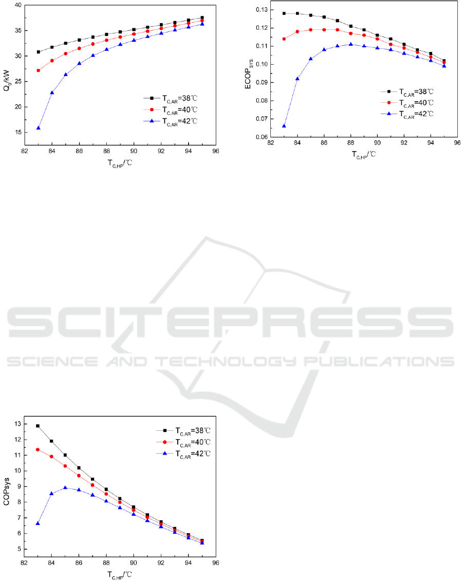
Figure 4: The curves between refrigerating capacity and
T
C,HP
.
According to the definition of in Eq. (7), COP
YSY
can intuitively reflect the electric power consumption
of the novel solar air conditioning system, instead of
reflecting the solar energy consumption. Fig. 5 shows
the variation of COP
SYS
with the condensation
temperature of SC subsystem (T
C,HP
). As can be seen
from Fig. 4, with T
C,HP
increasing, the electric power
consumption of the system also increases to transform
the low-level energy to a higher level, which leads to
a decline in COP
SYS
. Although high COP
SYS
provides
a better operating condition for the AR subsystem, the
electric power consumption caused by the HP
subsystem increases in a faster speed, which
ultimately leads to the decline of COP
SYS
. When T
C,HP
is set as 90 ℃, COP
SYS
is more than 7.5, which is
much higher than the normal vapour compression
refrigeration systems.
Figure 5: The curves between COP
SYS
and T
C,HP
.
Figure 6: The curves between ECOP
SYS
and T
C,HP
.
The novel solar air conditioning system adds the
heat pump as auxiliary equipment, which consumes a
certain amount of electric energy to ensure the normal
operation of the AR subsystem. Since the solar energy
and electric energy differ in quality, for the purpose
of getting a better view of the energy consumption of
the system, exergy analysis is carried out, which takes
the quality of energy into consideration. The exergy
efficiency of the novel system is defined as Eq. (8).
According to Eq. (8), ECOP
SYS
can indicate the
exergy consumption of the novel system. As can be
seen from Fig. 6, with T
C,HP
increasing, the exergy
efficiency of the novel system increases at first and
then decreases slightly. In a certain range of T
C,HP
, the
consumption of electric power brings a better use of
the exergy. When T
C,HP
is higher than a certain value,
more input exergy is supplied to the system and more
exergy losses occur.
Figs. 4-6 can be used to select design parameters
when the systematic design is carried out. To prevent
the risk of crystallization and to get a medium
COP
SYS
, T
C,HP
should not be too high. However, T
C,HP
should be as high as possible in order to get a larger
refrigerating capacity of the novel system. The
selection of parameter needs overall considerations.
5.3 The comparison of novel and
original system
In this section, the performance of the novel system
is compared with the original system through
quantitative calculation. The original system here is
composed of solar collectors and a single-effect LiBr
absorption refrigeration system, with no auxiliary
heating equipment. The calculation conditions
include two solar radiation intensities, the low solar
radiation I
L,SC
=0.4 kW/m
2
and the high solar radiation
I
H,SC
=0.8 kW/m
2
.
ICECTT 2018 - 3rd International Conference on Electromechanical Control Technology and Transportation
38

The refrigerating capacity (Q
0
) and the area of
solar collectors corresponding to unit refrigerating
capacity (A
s
) are selected as standards of the
comparison between the novel system and the
original system. The value of A
s
can reflect the initial
investment of the system to a certain extent.
The results of comparison between the novel
system and the original system under different
operating conditions are shown in Table 3. As seen in
Table 3, when the solar collectors work at a lower
temperature (T
1SC
=70 ℃) the novel system produces
34.32 kW and 9.00 kW refrigerating capacity
respectively in high solar radiation and low solar
radiation, while the original system fails to give
normal operation. When the solar collectors work at
a higher temperature (T
1SC
=80 ℃), the refrigerating
capacity of the new system is larger than the original
system. Through the comparison between two
systems, there is a conclusion that the novel system
are less affected by the weather condition. The novel
system has lower requirements for the performance of
solar collectors than the original system, which makes
the use of flat-plate collectors reasonable.
It also can be concluded from Table 3 that the
novel system needs much smaller area of solar
collectors to produce the same refrigerating capacity.
With the advantages of low requirements for the
performance of solar collectors and smaller area of
solar collectors, the initial investment of the novel
system is positive compared with the original system.
Table 3: Performance comparison of new solar air conditioning system and original solar air conditioning system.
T
1SC
=70 ℃
T
1SC
=80 ℃
I
H,SC
=0.8 kW/m
2
I
L,SC
=0.4 kW/m
2
I
H,SC
=0.8 kW/m
2
I
L,SC
=0.4 kW/m
2
Novel system Q
0
(kW)
34.32
9.00
28.31
4.28
Original system Q
0
(kW)
-
-
22.13
3.22
Novel system A
s
(m
2
/kW)
2.91
11.11
3.53
23.36
Original system A
s
(m
2
/kW)
-
-
4.52
31.06
It should be mentioned that the numerical
calculating results could be different if the operating
conditions change. However, the conclusion of the
advantages of the novel system will not be
overthrown.
6 CONCLUSIONS
In this study, for the analysis of a novel solar air
conditioning system with a heat pump as auxiliary
equipment, first law of thermodynamics and second
law of thermodynamics are applied in every
component. The main results obtained are concluded
below:
(1) The exergy analysis of the system shows that
the highest exergy destruction occurs in
condensation-generation and condensation 2. The
exergy destruction can be reduced with parameter
optimization.
(2) With the increase of T
C,HP
, the refrigerating
capacity of the novel system decreases, while the
COP
SYS
increases roughly. There is a value of T
C,HP
making the ECOP
SYS
maximum. When T
C,HP
=90 ℃,
COP
SYS
is more than 7.5.
(3) Compared with the original solar air
conditioning system, the novel solar air conditioning
system enjoys advantages of low requirements for the
performance of solar collectors and smaller area of
solar collectors.
Additionally, the results of the exergy analysis
presented in this paper can also be used in
thermoeconomic optimization of the novel solar air
conditioning system in future researches.
REFERENCES
Hwang, Y., Radermacher, R., Alili, A. and Kubo, I. (2008).
Review of Solar Cooling Technologies. HVAC&R
Research, 14(3), pp.507-528.
Sekret, R. and Turski, M. (2012). Research on an adsorption
cooling system supplied by solar energy. Energy and
Buildings, 51, pp.15-20.
Xu, S., Huang, X. and Du, R. (2011). An investigation of
the solar powered absorption refrigeration system with
advanced energy storage technology. Solar Energy,
85(9), pp.1794-1804.
Lass-Seyoum, A., Blicker, M., Borozdenko, D., Friedrich,
T. and Langhof, T. (2012). Transfer of laboratory
results on closed sorption thermo- chemical energy
storage to a large-scale technical system. Energy
Procedia, 30, pp.310-320.
Ahachad, M., Charia, M. and Bernatchou, A. (1993). Solar
absorption heat transformer applications to absorption
Energy Analysis and Exergy Analysis of a New Type Solar Air Conditioning System
39

refrigerating machines. International Journal of
Energy Research, 17(8), pp.719-726.
Jain, V., Kachhwaha, S. and Sachdeva, G. (2013).
Thermodynamic performance analysis of a vapor
compression–absorption cascaded refrigeration
system. Energy Conversion and Management, 75,
pp.685-700.
Prasartkaew, B. and Kumar, S. (2010). A low carbon
cooling system using renewable energy resources and
technologies. Energy and Buildings, 42(9), pp.1453-
1462.
Liu, Y. and Wang, R. (2004). Performance prediction of a
solar/gas driving double effect LiBr–H2O absorption
system. Renewable Energy, 29(10), pp.1677-1695.
Pérez de Viñaspre, M., Bourouis, M., Coronas, A., Garcı
́
a,
A., Soto, V. and Pinazo, J. (2004). Monitoring and
analysis of an absorption air-conditioning
system. Energy and Buildings, 36(9), pp.933-943.
Sumathy, K., Huang, Z. and Li, Z. (2002). Solar absorption
cooling with low grade heat source — a strategy of
development in South China. Solar Energy, 72(2),
pp.155-165.
Ali, A., Noeres, P. and Pollerberg, C. (2008). Performance
assessment of an integrated free cooling and solar
powered single-effect lithium bromide-water
absorption chiller. Solar Energy, 82(11), pp.1021-10
ICECTT 2018 - 3rd International Conference on Electromechanical Control Technology and Transportation
40
