
An Adaptive Light Algorithm for Extracting Track Information and
Its Control
Dong Liu and Yujun Wang
School of Computer and Information Science, Southwest University, Chongqing 400700, Chongqing, China
(mail:1617400837@qq.com phone number:13407279166)
Keywords: Unpowered vehicle, path tracking, PID algorithm.
Abstract: On the path-tracking problem of autonomous vehicle and the extraction threshold of track,which is affected by
the light, An unpowered intelligent vehicle and the corresponding control algorithm are designed in the paper.
First, the vehicle's mechanism is designed. Then, some structures for mounting the camera and the steering gear
are optimized. Next, the camera named LQ1286 is used to detect the path information in which the algorithm is
adapted for image binarization processing that extracting the white line for track recognition. Following, PID
algorithm is designed to adjust the angle of the steering servo mounted on the vehicle which is driven forward by
external fan wind. Thus the patrol is completed intelligently. Experimental results show that the design of
intelligent vehicle is able to complete the desired objectives.
1 INTRODUCTION
In recent years, energy and smart cars have become
the hotspots of scholars abroad. We encounter the
issue of combining energy and vehicles everywhere
in our daily life. All energy comes from nature, in the
past, we mistakenly believe that energy are excessive
and consume them too much. The car occupies a
large proportion of energy consumption, in order to
solve this problem, human beings need to use
sustainable energy. A non-powered car that this
paper design can identify the path and just to meet
this requirement. Furthermore, wind power
generation has become the main form of wind power
utilization, which is valued by all countries and
develops quickly. Wind power usually includes three
modes of operation: First, an independent operation,
usually a small wind turbine to provide electricity to
one or a few households, it uses battery energy
storage to ensure that the wind-free electricity; the
second is that the wind Power generation is
combined with other power generation, such as a
diesel generator, to power a single unit or village or
island. Third, wind power is integrated into regular
grid operations to provide electricity to the grid.
Often a wind farm installed dozens or even hundreds
of wind turbines, which is the main direction of wind
power. In view of the hot issue at home and abroad,
this paper proposes to use the external wind force to
enable the car to run autonomously on mountain
roads, hillsides and hills, and then automatically
install the fan on the car to the corresponding pole
through the cart.
At present, some people have designed a
controllable speed car, such as Freescale's
competition, through the PID algorithm and the
collection of the track information collection, you
can quickly complete the specified track patrol line.
However, they have not taken into consideration the
problem of patrolling the car without power and the
method of extracting the track using an adaptive
environment. The designed car can only walk in the
stadium of the match. As another example, someone
designed a solar-powered car that can convert clean
energy solar power into a car's power. But their
research is still based on people's driving forward,
and did not consider how to make the car
automatically. The car designed in this paper has
been tested experimentally and can achieve the
expected goal.
In this paper, a controller based on PID algorithm
and the algorithm of extracting track based on
adaptive light are designed. After collecting
information through the camera, the center of the
track is obtained. After the data is controlled by
discrete PD, get the Control amount. After
experimental verification, the car can meet the
expected requirements.
Liu, D. and Wang, Y.
An Adaptive Light Algorithm for Extracting Track Information and Its Control.
In 3rd International Conference on Electromechanical Control Technology and Transportation (ICECTT 2018), pages 265-270
ISBN: 978-989-758-312-4
Copyright © 2018 by SCITEPRESS – Science and Technology Publications, Lda. All rights reserved
265
2 THE DESIGN OF
MECHANICAL SYSTEM AND
ITS IMPLEMENTATION
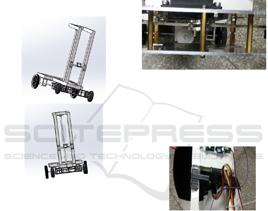
2.1 The mounting mechanism of servo
The car is mainly composed of the rear wheel, front
wheel, camera and car bracket (for the installation of
fan), as shown in Figure 1.
Fig.1 Simplified model of unpowered car
Taking into account the rules of the game said
that only one steering mechanism can be used, we
have a larger adjustment of servo mechanism. The
steering of racing car is realized by the driving left
and right tie rods. The servo rotation speed and
power is certain, in order to speed up the response
speed of the steering mechanism, the only way is to
select the servo installation location and its length of
the rod reasonably. As the power is a function of the
speed and torque, under the premise of constant
power, the excessive pursuit of speed will inevitably
take the loss of torque and the torque is too small will
also cause the steering to be slow, so this design
considering the response speed of the steering
mechanism and the steering gear .Based on the
collection of physical parameters, the final
parameters and structures that can work stably and
efficiently are obtained. After calculation and
optimization, the designed servo gear (steering rod),
taking into account the relationship between speed
and torque, so that the installation is easier. The
installation of the steering gear mechanism is shown
in Figure 2.
Fig.2
The structure of steering engine
2.2 Camera mounting mechanism
For the installation of the camera, we used a 3D
printer to print a stand, so that we can easily replace
the camera. We will install the camera in the center
of the car, and the camera is not far from the track, so
the camera can collect the information more
intensive, and the information collected is not
distorted. As shown in Figure 3.
Fig.3 The structure of camera
2.3 Power source - fan
Because the competition requires that the car itself
can not carry any power source which can make it
move forward, and the car is not allowed to move on
in the final stage of the journey. Therefore, we use
the channel fan to blow the car, the model of Channel
fan is shown in Figure 4.
ICECTT 2018 - 3rd International Conference on Electromechanical Control Technology and Transportation
266
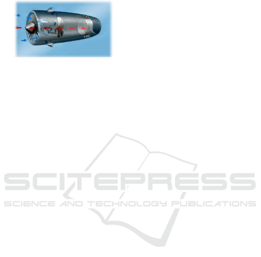
Fig.4 the channel fan
3 THE DESIGN OF PID
CONTROLLER AND ADAPTIVE
LIGHT ALGORITHM
3.1 The Introduction of PID Control
In engineering practice, the Controller which is
widely used is proportional, integral, differential
control, referred to PID control. Because of its
simple structure, good stability, reliable, easy
adjustment and other advantages , PID controller has
become one of the major technologies in industrial
control. When the structure and parameters of the
controlled object can not be completely mastered, or
the precise mathematical model can not be obtained,
the structure and parameters of the system controller
need to be determined by experience and on-site
commissioning. At this time, it is most convenient to
apply PID control technology. PID controller's basic
working principle is shown in Figure 5.
3.2 PID setting and feedback acquisition
For the track, this article mainly through the linear
camera to collect information,then make the
information binary processing. That is, for different
colors, the values collected by the cameras are
different. In this paper, the formula (1) is used for
processing, and the processed trajectory information
is shown in FIG. 6.
⎩
⎨
⎧
−<
>
=
))(max(0
))-(max(1
)(
a
a
f
x
η
η
(1)
3.3 Adaptive environment for extracting
white track
3.3.1 Adjust the exposure automatically
according to the environment
Because the linear CCD will lead to great changes in
the analog acquisition caused by Ambient light, so
we must adjust the amount of exposure according to
the light intensity, so the camera will not be
saturated under strong lighting conditions. The
specific algorithm is as follows:
First of all, by getting the maximum value of the
algorithm, we calculate the maximum of 128 sets of
data, as max.
If max> 4096
Note: 4096 is the maximum when the linear CCD
is on saturation, this value can be reduced based on
the actual situation.
If max <1200
Increase the amount of exposure
3.3.2 Get the value of
a
Through many experimental measurements, we
found that when the vaule of
a
is 70, and the
length of the white track is about 3.
3.3.3 Get center of the track
According to the maximum max, combined with the
formula (1), we binarize the data to get the center of
the track.
2/jicenter +=
(2)
Where
i
is the start of the white track,
j
is
the length of the white track,
cente
r
is the center
of the white track.
After calculating the center point of the track, the
deviation between the center point and the center
point is obtained,which is shown in equation (3).
α
/)12(
)(
centercentere
t
−=
(3)
a
is the distance between two acquisitions,
t
is signs.
An Adaptive Light Algorithm for Extracting Track Information and Its Control
267
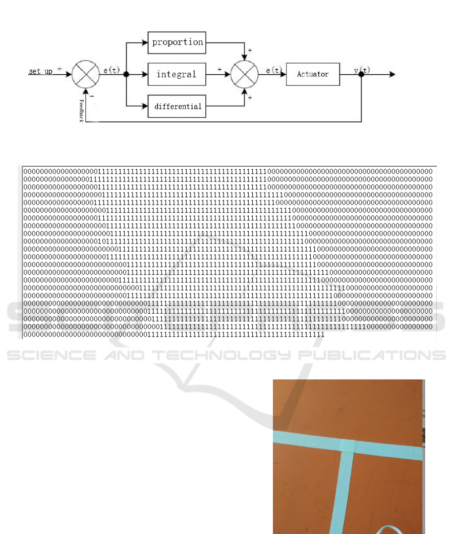
Fig.5 the block diagram of PID
Fig.6 the trajectory’s information
Through the previous steps, we can get the
control of steering servo by PD control,as formula
(4).
() ( 1) ( 1) ( 2)
[]
kpk dk k
uke ke e
−−−
=+ −
(4)
Where
)(te
is the error function, where the
error is twice. So far the control of the steering gear
is obtained, and the control of the steering gear can
complete the designated track task.
3.4 Method of crossing the crosshairs
Figure 7 is the "T" word line track which is
required in race. For the "T" or "ten" shape track,
this paper adopts the white track width to
distinguish, that is, when the camera detects the
width of the white line is greater than a threshold,
then the program automatically determine the cross
, Turn left directly.
Fig.7 the T type line
ICECTT 2018 - 3rd International Conference on Electromechanical Control Technology and Transportation
268
4 THE RESULTS AND
ANALYSIS OF EXPERIMENT
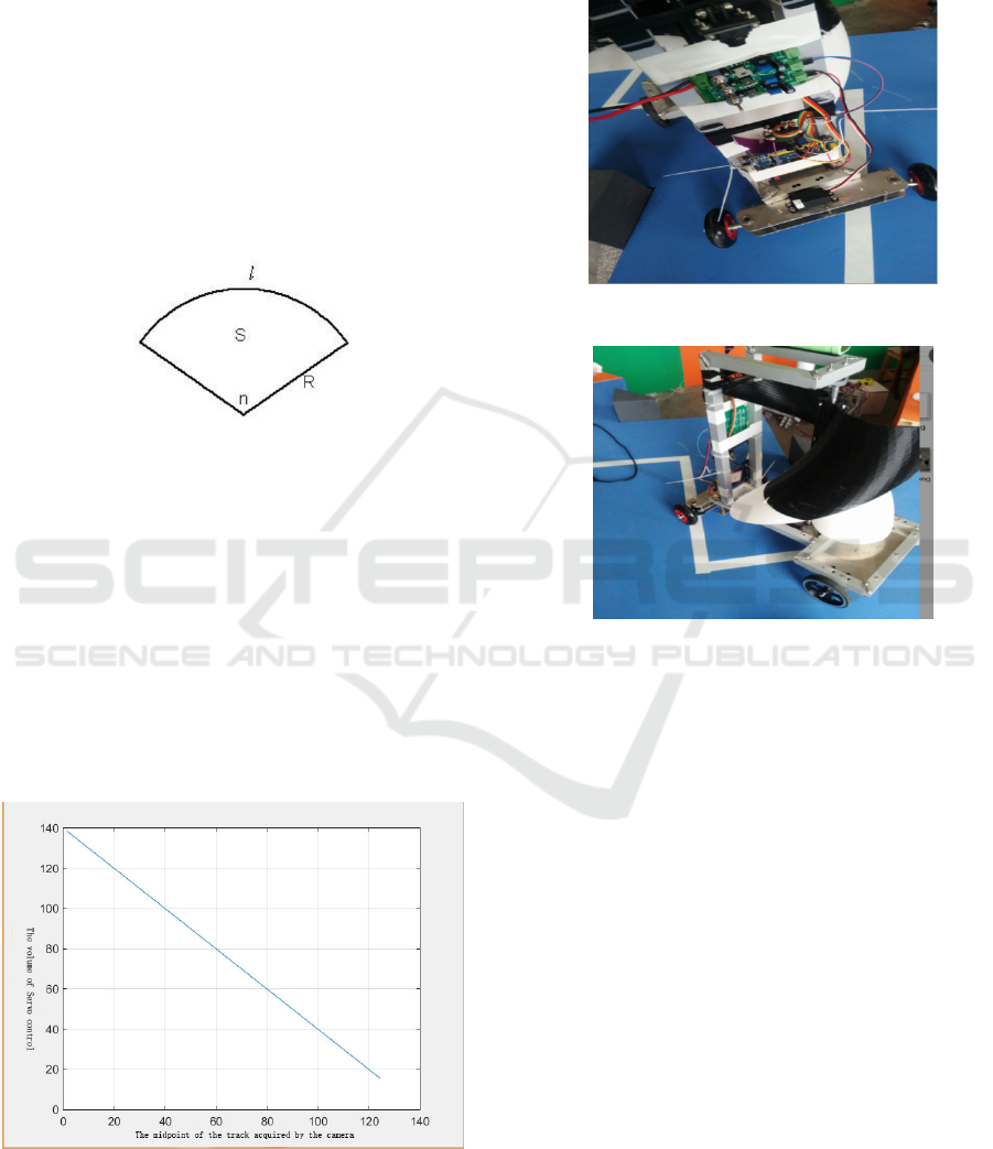
4.1 Parameter initial setting
In the experiment, we will make parameters k
matched to the camera and the track information
through linear conversion, so the parameters will be
the same. Since the system is a linear system, the
information detected by the camera will be the
same as the servo should have at this moment. The
specific principle is shown in Figure 8, the steering
gear parameters n and l is a linear relationship.
Fig.8 the picture of theory
The initial simulation by Matlab, the simulation
is shown in Figure 9. Simulation diagram abscissa
camera to collect the white track midpoint and the
program control the servo one by one, just to meet
a linear functional, and it meets with the analysis
in Figure 8.
the results of Simulation show that when the
camera detects the mid-point of the track, the value
of the steering gear is just the corresponding
midpoint, so from the previous analysis, the
parameter setting is reasonable.
Fig.9 the simulation
4.2 The test on Real track
The experimental process is shown in Figure 10
and Figure 11.
Fig.10 Passing the T type line
Fig.11 passing the broken line
In the experiment, the hand-push method is
used to drive the car to move forward. When the
car passes the T-shaped track as shown in FIG. 10,
the camera can correctly identify the T-shaped
track, and the steering wheel can automatically turn
left. When the car through the track as shown in
Figure 11, the car can be very good to make the
broken line as a curve to travel. The car can
successfully complete the game requirements, after
testing, the program designed in this paper, can
complete the desired line mission.
5 CONCLUSION
For the task of autopilot line, wo transform the
Right angle polyline into non-right-angle broken
line,and then the program is combined with the PID
algorithm for precise control of the steering wheel,
Finally the car that we design can basically achieve
the control of smart vehicles tasks.
An Adaptive Light Algorithm for Extracting Track Information and Its Control
269

We will consider the following aspects to
improve:
a) Reduce the mass of the car so that the car
can run faster with the same wind force.
b) Use color sensor. As the camera is
susceptible to environmental interference, the use
of color-coded sensors can improve the stability of
autonomous patrol line.
c) Optimize the camera's perspective so that it
has the ability to anticipate the track.
REFERENCES
Tao Yonghua. The new PID control and its application
[M]. Machinery Industry Press, 2002.
Huang Yourui, Qu Liguo PID controller parameters
tuning and implementation [M]. Science Press,
2010.1.
Zheng Archie .MATLAB Tutorial [M]. Electronics
Industry Press, 2014.11.
Zhao Jingbo .MATLAB control system simulation and
design [M] .Machinery Industry Press, 2010.8.
Liu Ke Yi, Schubert, Xu Guoqiang. The seventh smart
car Beijing University of Technology camera group
experiment report [J], 2013.4.
Yin Jianhong, Wu Kaai. Graph theory and its algorithm
[M]. China University of Science and Technology
Press, 2003.
Tan Hao strong. C programming [M]. Beijing: Tsinghua
University Press, 2003.
Yan Shi. Digital electronic technology foundation [M].
Beijing: Higher Education Press, 2000.
Zhuo Qing, Huang Kai Sheng, Shao Beibei and so on.
Learn to make a smart car - challenge "Freescale"
cup [M]. Beijing: Beijing University of Aeronautics
and Astronautics Press, 2007.3.
Zhang Youtong, Chen Baojiang. Automotive electronic
technology principles and applications [M]. Beijing:
Beijing Institute of Technology Press, 2006.
Shao Beibei. Embedded real-time operating system [LC
/ OS-Ⅱ (second edition) [M]. Tsinghua University
Press, 2004.
The 15th RoboCon National University Robot
Competition in 2016.
http://www.saikr.com/cnrobocon
ICECTT 2018 - 3rd International Conference on Electromechanical Control Technology and Transportation
270
