
Robust Controller Design of Hypersonic Vehicle in Uncertainty
Models
Nan Wu and Jia Yu
1School of Aeronautic Science and Engineering, Beihang University, Beijing, China
Keywords: Hypersonic vehicle, robust controller, H
2
/H
∞
, norm,uncertainty models.
Abstract: This paper studies the controller of the air-breathing hypersonic vehicle. Taken the inertia into
consideration, the control law of an air-breathing hypersonic vehicle is designed when the aircraft's
appearance and aerodynamic parameters are changed. Due to the traditional controller is too dependent on
the mathematic model of targets, the H
2
/H
∞
control law of the air-breathing hypersonic vehicle is designed
using the robust controller method. The rigid body model of the aircraft and the uncertainty model are
researched in this paper. Then the corresponding robust controller is designed based on the uncertainty
model in the case that the aircraft flies in different pitch angles. Finally, the stable flight characteristics of
the hypersonic vehicle using the robust controller are verified in the complex flight conditions, compared to
the general stability control system.
1 INTRODUCTION
Aspirated hypersonic vehicles have different degrees
of uncertainty in their aerodynamics, propulsion and
structure owing to their wide range of flight,
complicated flight environment, fast flight speed and
obvious aerodynamic heating effects (Bertin J J,
2003; Mcnamara J, 2011). Due to the integrated
design, there is a strong coupling between
subsystems such as aerodynamics, propulsion and
structure (Cockrell C E, 2001). This coupling effect
may amplify the uncertainty of the system, so that
the aircraft dynamics characteristics deviate from the
design goals, which even cause the control system
failure. For example, X-43A is out of control in the
first test flight because of uncertainty beyond the
control system Stability boundary. The LPV method
uses more modern control techniques in design and
adopts norm-based performance measurement of
control systems, control methods, singularity
methods, and parametric methods based on
decomposition. Among them, the influence of
system uncertainty is fully considered, which has
generality, is suitable for practical engineering
application. However, this control method also has
some negative defects, that is, it sacrifices other
performance of the control system, resulting in poor
dynamic mass of the system.
In the 1960s, a design method based on LQG
feedback control was proposed. The optimal
controller was designed, considering the dynamic
performance, steady-state performance and control
energy of the system. When the system was input
with interference such as pulse and white noise, the
output energy is the minimum, but the control
method cannot guarantee the robustness of the
system when there is uncertainty in the controlled
system. Therefore, H
2
/H
∞
controller method is
proposed, whose design idea is to combine H
∞
performance design with the H
2
performance design.
As a result, the method make the closed-loop system
has good robustness and excellent system
performance (Zhang WeiGuo, 2012).
In this paper, a rigid body dynamics model of
hypersonic vehicle is established for the problem of
uncertainty of hypersonic vehicle. The H
2
/H
∞
controller is designed to compare with the K
feedback stabilization under the influence of
uncertain parameters respectively, which can be
used to verify the uncertainties problem.
2 HYPERSONIC AIRCRAFT
RIGID BODY DYNAMICS
MODEL
In this paper, the wave-rider configuration of the
hypersonic vehicle is researched by establishing the
rigid body model (Oppenheimer M, 2013; Bolender
288
Wu, N. and Yu, J.
Robust Controller Design of Hypersonic Vehicle in Uncertainty Models.
In 3rd International Conference on Electromechanical Control Technology and Transportation (ICECTT 2018), pages 288-293
ISBN: 978-989-758-312-4
Copyright © 2018 by SCITEPRESS – Science and Technology Publications, Lda. All rights reser ved
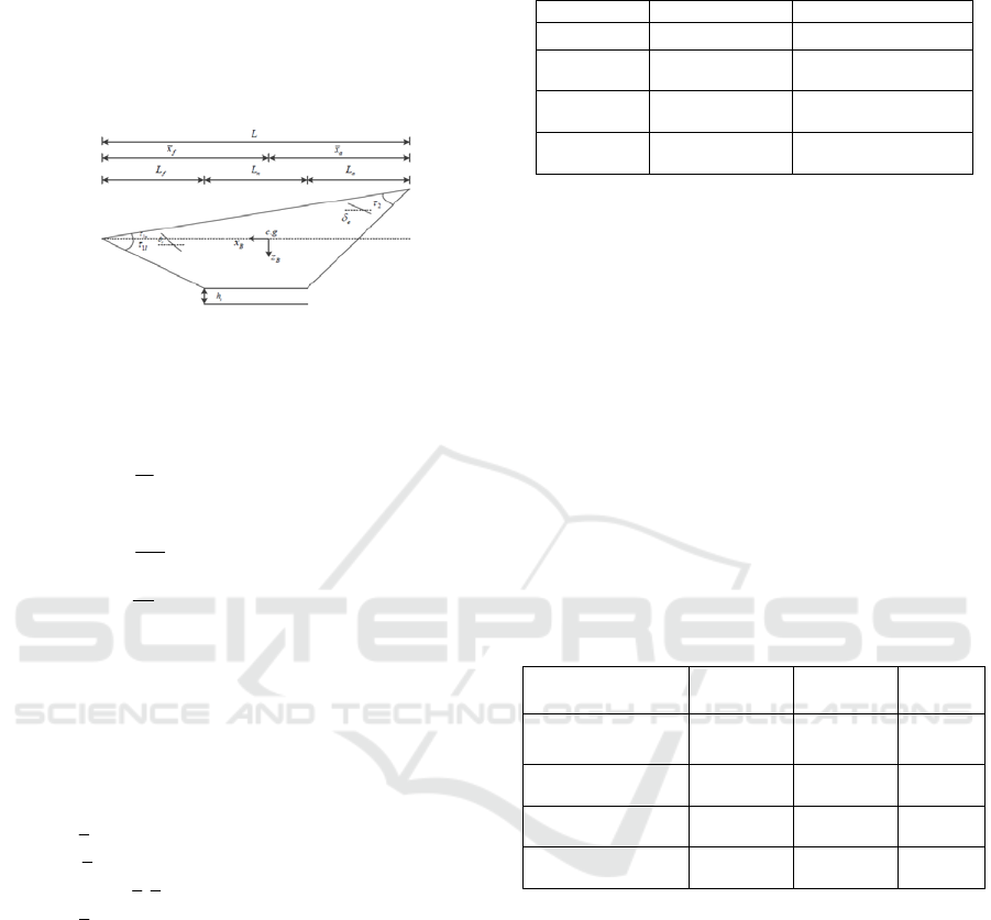
M A, 2012; Parker J T, 2012). The layout of the
aircraft is shown in Figure 1. Where
f
L
is the fore-
body length;
n
L
is the engine length;
a
L
is the body
length;
e
is the elevator deflection;
c
is canard
deflection;
1
is the fore-body deflection;
2
is the
body deflection.
Figure 1 Hypersonic vehicle layout diagram
According to Lagrange equation, using a stable
axis coordinate system, the hypersonic longitudinal
rigid body dynamics model can be described as
sin
sin
cos( ) /
y
X
Vg
m
hV
Z
qg V
mV
M
q
I
q
(1)
Where V、h、
、q、
are five rigid body
state variables for hypersonic aircraft; m、M、
y
I
is
the mass, moment and moment of inertia of the
aircraft, respectively. Reference (AIAA, 2009)
provides a curve fitting model of aerodynamic data,
shown in Eq. (2).
,
(, , )
(, , )
(, , )
[(,)(,)]
Lec
Dec
TMec
TT
LqSC
DqSC
MzTqScC
TqC M C M
(2)
Where
T
z is the thrust of the coupling coefficient
of the moment; Three control input including
elevator deflection angle
e
, canard deflection
c
and fuel equivalent ratio
;
,T
C
is the thrust
coefficient and the ratio of fuel equivalence ratio;
T
C is the thrust coefficient. Specific aerodynamic
coefficients of the fitting expression can be detailed
in reference 8.
The hypersonic aircraft flight Mach number is
selected as 8Ma. The flight altitude is 85000ft. The
given constraints are shown in table 1. The balance
state is calculated using the hypersonic rigid body
model as follows.
Table 1 the equilibrium state at the speed of 8Ma and the
height of 85000ft
Quantity of state Array
Initial value
[]Vh q
[7846,85000,1,0,1]
Control
inpu
t
[]
e
[3.9138, 0.5424]
Balance
poin
t
[]Vh q
[7846, 85000,1,0,1]
State
derivate
[]dV h q
1.0e-
11*[0.60330,0,0,0,0]
Under this equilibrium state, characteristics root
of air-breathing hypersonic aircraft is given in table
2. It can be seen from Table 2 that the rigid body
model of the hypersonic vehicle is composed of a
short-period mode, a long-period mode and a high-
level mode. Among them, the short-period mode
consists of two real poles distributed almost
symmetrically with the imaginary axis, showing
unstable characteristics. The long-period mode
consists of a pair of complex conjugate poles, which
are characterized by low frequency, under-damped.
Its height-period modal is near the origin, which can
be neglected. Thus, the aspirated hypersonic vehicle
shows the characteristics of longitudinal instability.
And the controller must be designed to control it to
ensure the longitudinal stability of the hypersonic
vehicle with good flight characteristics.
Table 2 The zero pole of hypersonic aircraft
Characteristic
root
Damping
ratio
Free
fre
q
uenc
y
Mode
5
2.6134 10 0.0365
i
4
7.16 10
0.0365 Long-
period
-9.3822 1 9.3822 Short-
period
9.2952 -1 9.2952 Short-
period
-0.00205152 1 0.0020 Height-
period
3 MODEL UNCERTAINTY
ANALYSIS
In the process of modeling the air-breathing
hypersonic vehicle, control law is designed easily
for the longitudinal linear model, some ideal
assumptions have to be made. Therefore, errors
introduce uncertainty into the linear analysis model.
These uncertainties have unpredictable interference
with aircraft stability, maneuverability and control
laws and may even cause serious accidents.
Therefore, it is necessary to study in detail the
uncertainties in the aircraft model. This paper
summarizes the uncertain factors introduced in the
Robust Controller Design of Hypersonic Vehicle in Uncertainty Models
289
dynamics modeling process. The structural singular
value method is selected to analyze the uncertainty
parameters in the mode, considering the effects of
these parameters on the vehicle.
As shown in Table 3, the corresponding mass,
center of gravity, moment of inertia and change of
structure elastic frequency of the aspirated
hypersonic vehicle under different fuel conditions
are given. On this basis, combined with the analysis
of the modal characteristics, the range of uncertainty
of each major uncertainty parameter is obtained.
Table 3 Uncertain parameters range in different fuel
Fuel
0%
30%
50%
70%
100%
()mslug
93.57 126.1 147.
9
169.6 202.2
52
10 ( . )
I
yslugft
1.56 2.102 2.46
5
2.827 3.37
()
f
x
ft
53.1 53.61 53.8
2
53.98 54.16
1
(/)rad s
22.78 21.71 21.1
7
20.73 20.17
2
(/)rad s
68.94 57.77 53.9
2
51.24
48.4
3
(/)rad s
140
117.8 109.1
102.7
95.6
According to the analysis of references (Yujia,
2015), through the analysis and synthesis toolbox of
Matlab, we can calculate the singular value of the
system perturbed by the inertia factor, the
aerodynamic parameters and the perturbation of the
aircraft profile. The results show that the rigid
hypersonic vehicle model is affected by inertia
factors, aerodynamic parameters and aircraft shape.
4 H
2
/H
∞
CONTROLLER DESIGN
AND SIMULATION
Air breathing hypersonic vehicles have a wide range
of flight, complex flight environment and fast flight
speed. The dynamic model of the whole system has
a wide range of changes, so that the structure and
parameters of the flight control system will change
as the vehicle changes. Considering the above
characteristics, the flight control system of the
aspirated hypersonic vehicle must meet the control
requirements with large range of parameters and
high uncertainty of the model.
Based on this requirement, the robust flight
control design method is adopted to make the flight
control system of the hypersonic vehicle have good
robustness and excellent flight performance. H
2
/H
∞
robust control method is used to control the aircraft,
based on LMI.
4.1 H
2
/H
∞
Control
The control idea of H
2
/H
∞
is to combine the
performance design of H
∞
and H
2
so that the closed-
loop system has good robustness and good system
performance. The H
2
/H
∞
control structure is shown
in Figure 2.
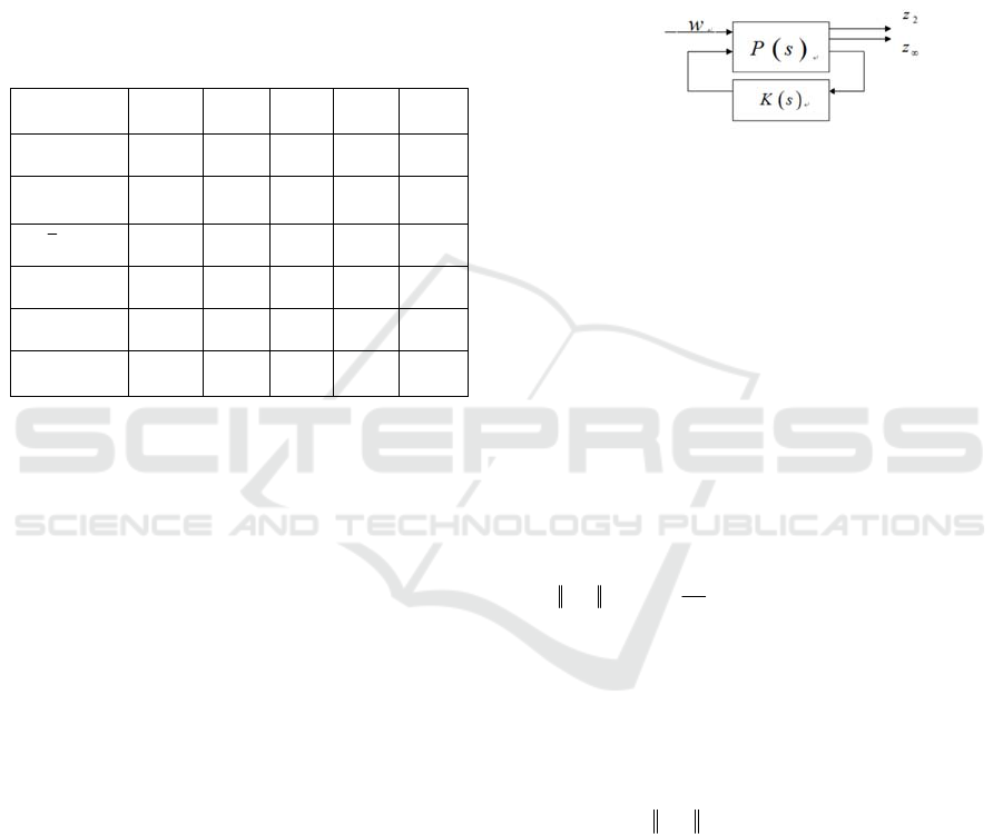
Figure 2 The definition of H
2
/H
∞
control
Where P (s) is the generalized linear time plant
structure, K(s) is the controller of H
2
/H
∞
. Equation 3
describes state equation of P (s).
12
12
22 21 22
x
Ax B w B u
zCxDwDu
zCxDwDu
(3)
Where
u
is the control effectors variable;
w
is
the uncertainty matrix input variable (including
disturbance input, instruction input etc.);
2
z and z
are output of H
2
/H
∞
. H
2
and H
∞
norm are defined as
follows:
1/ 2
*
22
2
1
() () ()
2
Zw Zw
Ts Trace T j T j d
(4)
Where
2
Z
w
T is the transfer function from
w
to
2
z
;
*
2
Z
w
T
is the conjugate transposed matrix of
2
Z
w
T
;
Trace
is the trace of the matrix. The square of H
2
norm is the system impulse response of the output
energy.
max
() sup ( )
Zw
Ts T j
(5)
Where
Z
w
T
is the transfer function from
w
to
z
.
H
∞
norm represents the peak value of the maximum
singular value of the system response frequency.
The state feedback controller can be expressed as
uKx
(6)
Substituting equation (6) into equation (3), the
corresponding closed-loop system state space is
described as:
ICECTT 2018 - 3rd International Conference on Electromechanical Control Technology and Transportation
290

21
21
2 2 22 21
()
()
()
x
ABKxBw
zCDKxDw
zCDKxDw
(7)
4.2 LMI Region and D-Stability
A basic problem in control theory and practice is
to design a feedback control law that positions the
poles of the closed-loop system in the desired
position to ensure that the closed-loop system has
the required dynamic and steady-state performance.
However, due to the inaccuracy of the model and the
existence of various disturbances, the poles of the
closed-loop system should be placed in a suitable
area on the complex plane.
The required regions are as follows: to ensure
that the state response to the attenuation of the half-
plane, the minimum damping ratio, the maximum
natural frequency (Chilali M, 1996), shown in
Figure 3. Adjusting this area can make the system's
maximum overshoot, adjustment time, rise time,
oscillation frequency and other time-domain
response indicators meet the expected requirements.
Eigenvalue area can use a Linear Matrix Inequality
(LMI) to describe (Yuli, 2002).
In this paper, according to the relevant
hypersonic vehicle data, the frequency is selected as
2~4 and the damping ratio is selected as 0.6~0.9.
The final selected area is a sector centered at (-4,0),
a radius of 4 and an included angle of 120 degrees.
Figure 3 Closed-loop pole LMI area
4.3 Controller Design and Simulation
In this paper, the rigid body modes, rigid body
dynamics and structural dynamics of the aspirated
hypersonic vehicle are weakly coupled only between
the short-period and the first-order elastic motions.
That is, the rigid body modes do not excite the
elastic modes and the aero-elasticity Modal will not
stimulate rigid body mode. The H
2
/H
∞
controller at
the balance point is designed. The matrix parameters
of generalized controlled system are as follows.
0 0 -1.0953e2 0 -3.2150e1
0 0 7846 0 7846
-1.0572e-6 1.9419e-6 -1.2374e-1 1 0
0 -3.8714e-6 1.1101e1 0 0
00010
A
1
0.0185
1
0.01589
0.0014
0.008
B
2
36.667 41.573
00
0.0161 0.0001
4.6860 0.0209
00
B
00000
00000
00100
00010
00000
C
2
010.7 1 0
00000
1 1 0.5 0 0.2
11 0 0.5 0
000.10.10.8
C
121
0
0
0
0
0
DD
2
00
00
00
00
00
D
22
00
00
11
11
11
D
For hypersonic aircraft, the control system needs
to give priority to ensuring robustness. For the H
∞
norm constrained optimization iteration of the
generalized linear time-invariant system P(s), we get
the optimal threshold value of H
∞
norm is 0.24,
which indicates that H
∞
norm is
1
0.24
in the final
H
2
/H
∞
design. By H
2
norm constrained optimization
iteration of P(s), the optimal H
2
norm value is 2.01,
corresponding to H
∞
= 0.45. So H
∞
norm is selected
as
1
0.24 0.45
.
When the H
∞
index γ
1
becomes larger, it can be
seen that the system robustness becomes stronger
and the dynamic performance is worse. So the
choice of γ
1
needs to be taken into account. The H
2
and H
∞
nostrils are approximately inversely
proportional. When the H
∞
norm increases to 0.4, the
H
2
norm is almost invariant. So γ
1
= 0.4 is selected,
and the H
2
norm corresponding to this is taken as
2.55. The controller state matrix is:
8.5487 1.1192 0.2161 0.1994 0.5475
28.5022 23.8086 4.0025 2.4283 1.5220
22.2929 11.9760 7.8630 5.2365 40.0805
84.6104 79.7104 22.6790 0.4907 36.8523
7.6919 7.0448 1.7637 0.8601 5.8979
K
A
33
3434
44 4
4545
177.5367 4.5970 1.4933 10 28.5387 6.1444 10
2.9410 10 5.8339 6.8808 10 1.4759 10 1.0087 10
857.3554 11.3396 6.1016 10 1.5855 10 1.0071 10
1.3881 10 39.2010 4.9033 10 5.3110 10 3.0183 10
1.116
K
B
3434
4 10 4.6595 4.5228 10 1.9587 10 7.1836 10
44 4
54
0.0013 6.2453 10 2.0713 10 4.0358 10 0.0035
0.0027 0.0015 1.8815 10 5.2469 10 0.0035
K
C
Robust Controller Design of Hypersonic Vehicle in Uncertainty Models
291
00000
00000
K
D
After the introduction of robust state feedback
controller, the pole is -2.3545 ± 2.3076i. The short-
period damping of the system is 0.714 and the
frequency is 3.297. The variation of frequency
shows that the dynamic characteristics of the system
are improved. The damping increase indicates the
robustness of the system increases. It can quickly
return to equilibrium under external disturbance or
system state changes.
In the following, an ordinary steady-state
feedback K is introduced, compared with the state
feedback of H
2
/H
∞.
It is verified that the H
2
/H
∞
hybrid controller still guarantees a good control
effect under the condition of large system
uncertainty.
-0.0002 0.0799 -110.3370 -0.3480 113.5158
-0.0007 -0.0097 -209.3452 0.4513 215.5714
0.1344 0.0741 25.2763 -0.5639 -30.5862
K
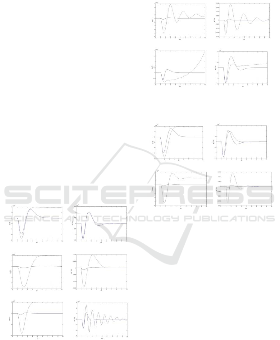
The system adds (1°, 1s) the elevator step
response. Δ0 is the case of no parameter perturbation.
Δ1, Δ2 are the two parameters perturbation of the
cutoff, respectively. In figure 4, dotted line
represents normal feedback K and solid line
represents H
2
/H
∞
mixed controller feedback. And
The inertial parameters perturbation response is also
shown.
(1) 0 The angle of attack (2) 0 The rate of pitch
(3) 1 The angle of attack (4) 1 The rate of pitch
(5) 2 The angle of attack (6) 2 The rate of pitch
Figure 4
Taken the aerodynamic parameters into account,
the system responds to (1°, 1s) the elevator's step
response is shown in Fig.5.
(1) 1
The angle of attack (2) 1 The rate of pitch
(3) 2
The angle of attack (4) 2 The rate of pitch
Figure 5
Taken the aircraft shape parameter into account,
the system responds to (1°, 1s) the elevator's step
response is shown in Fig.6.
(1) 1
The angle of attack (2) 1 The rate of pitch
(3) 2
The angle of attack (4) 2 The rate of pitch
Figure 6
As can be seen from the response curves of each
state in the figure, in the model with robust control,
the angle of attack and the rate of pitch of the
closed-loop system converge faster and have almost
no oscillation after being perturbed. And the
equilibrium state can be recovered faster. In the
system with parameter perturbation, the closed-loop
system can still maintain the stability. However, the
amplitude of the shock is very large and even
diverges after the parameter is perturbed without
adding the model of robust control. It shows that the
robust control closed-loop system is robust and has
good maneuverability.
5 CONCLUSIONS
This article is aimed at uncertain control problems of
aspirated hypersonic vehicle in flight, considering
complicated flight environment and uncertainty of
aerodynamic configuration. According to the results
of the uncertainty analysis of the structure singular
value method, a robust control method is used to
ICECTT 2018 - 3rd International Conference on Electromechanical Control Technology and Transportation
292

design the control law of a hypersonic vehicle
considering the inertia, the aerodynamic parameters
and the aircraft shape uncertainty. The simulation
results are compared with the ordinary augmentation
system. After adding the perturbation parameter, the
response curves of the angle of attack and the rate of
the pitch ordinary augmentation system fluctuate
greatly and even the divergence occurs. The
response curves of the pitch velocity of the robust
control system converge very quickly, almost no
shock. The comparison results show that the control
law design of ordinary stabilization system cannot
solve the problem of stability control of hypersonic
vehicles with uncertainties. However, the H
2
/H
∞
robust control method can solve this problem well
and has good control effect.
REFERENCES
Bertin J J, Cummings R M. Fifty years of hypersonics:
where we've been, where we're going
[
J
]
.
Progress in Aerospace Sciences,2003, 39(6):511-
536.
Mcnamara J, Friedmann P. Aeroelastic and
Aerothermoelastic Analysis in Hypersonic Flow:
Past, Present, and Future
[
J
]
. Aiaa Journal,
2011,49(6):1089-1122.
Cockrell C E, Engelund W C, Bittner R D. Integrated
Aeropropulsive Computational Fluid Dynamics
Methodology for the Hyper-X Flight Experiment
[
J
]
. Journal of Spacecraft & Rockets , 2001,
38(6):836-843.
ZhangWeiGuo.Robust flight control system
design[M].Changsha.National defense industry
press,2012:page 105-136.
Oppenheimer M, Skujins T, Bolender M, et al. A Flexible
Hypersonic Vehicle Model Developed with Piston
Theory[C]// AIAA Atmospheric Flight Mechanics
Conference and Exhibit. 2013.
Bolender M A, Doman D B. Nonlinear Longitudinal
Dynamical Model of an Air-Breathing Hypersonic
Vehicle
[
J
]
. Journal of Spacecraft & Rockets,
2012,44(2):374-387.
Parker J T, Serrani A, Yurkovich S, et al. Control-
Oriented Modeling of an Air-Breathing Hypersonic
Vehicle
[
J
]
. Journal of Guidance Control &
Dynamics
,
2012, 30(3):856-869.
AIAA. Development Of Linear Parameter-Varying
Models Of Hypersonic Air-Breathing Vehicles[C]
AIAA Guidance, Navigation, and Control
Conference. 2009.
Yujia,Yangpengfei. Hypersonic vehicle model uncertainty
impact analysis[J].Journal of
aviation.2015,(1):192-200.
Chilali M,Gahinet P. H∞ Design with Pole Placement
Constraints: an LMI approach
[
J
]
.IEEE
Transactions on Automatic Control , 1996 ,
41(3):358-367.
Yuli.Robust control,linear matrix inequality LMI
approach[M].Beijing:Qinghua university
press,2002.
Zhang qing-jiang.With regional pole assignment of
H2/H∞ control [D].Xian:Nothwestern poly
technical university,2006.
Robust Controller Design of Hypersonic Vehicle in Uncertainty Models
293
