A Numerical Simulation of Smoke Extraction in the Tunnel Sidewall
Yu Li and Shijie Cai
School of Civil and Safety Engineering, Dalian Jiaotong University, Dalian, Liaoning, China, 116028
467797823@qq.com
Keywords: Fire, sidewall smoke-extraction, smoke-extraction rate, efficiency.
Abstract: The rectangular tunnel (450 m × 10 m × 5 m) and smoke vent (4.5 m × 4.5 m) located on the sidewall, with
its bottom flush with the ground, were simulated to analyze the law of smoke extraction in the tunnel sidewall.
Numerical simulations were conducted to analyze the law of smoke extraction in the tunnel sidewall at
different rates of smoke extraction. Based on the results, the output of the smoke extraction system decreases
with the increase in extraction rate. By contrast, the efficiency of the smoke extraction system increases with
the increase in smoke extraction rate.
1 INTRODUCTION
Timely and efficient extraction of smoke from the
tunnel is one of the crucial technologies in
emergency rescue during a fire (Jiang Xuepeng,
2014; Hu Longhua, 2005; Jiang Yaqiang,2010; Han
Jianyun, 2013; Jiang Yaqiang, 2009). Therefore,
analyzing the law of smoke extraction in tunnels is
significant.
In this regard, Li et al. (2013), Hu et al. (2008),
and Oka et al. (1995) investigated the relationship
between the distance of backlayering and the
longitudinal velocity of the wind, which is the
critical velocity of the wind for restraining the
countercurrent flow of smoke. Wu and Bakar (2000),
Vauquelin and Telle (2005), and Tanaka et al. (2015)
conducted macroscopic studies on the efficiency of
horizontal extraction, including the rate of extraction
at the smoke vent, the shape and location of the
smoke vent, the power of the fire source, and the
influence of the relative position of the smoke vent
and air inlet on the efficiency of smoke extraction.
During the construction of an extra-long tunnel, a
level gallery would be dug for every 400-500m in
the tunnel sidewall in order to facilitate
transportation, which leads to the outside of the
tunnel. When the tunnel is built, the gallerys’
openings are naturally used as smoke vents. So in
this study, we assume one smoke vent should be set
for every 450m in the tunnel sidewall.
2 NUMBERICAL SIMULATION
2.1 Design of The Model of The Tunnel
In this study, FDS 5.5.3 is employed (version,
published in 2012). A model of the fire can be
established, and movement of smoke, temperature,
and toxic concentration during the fire can be
predicted (Liang Ping, 2010).
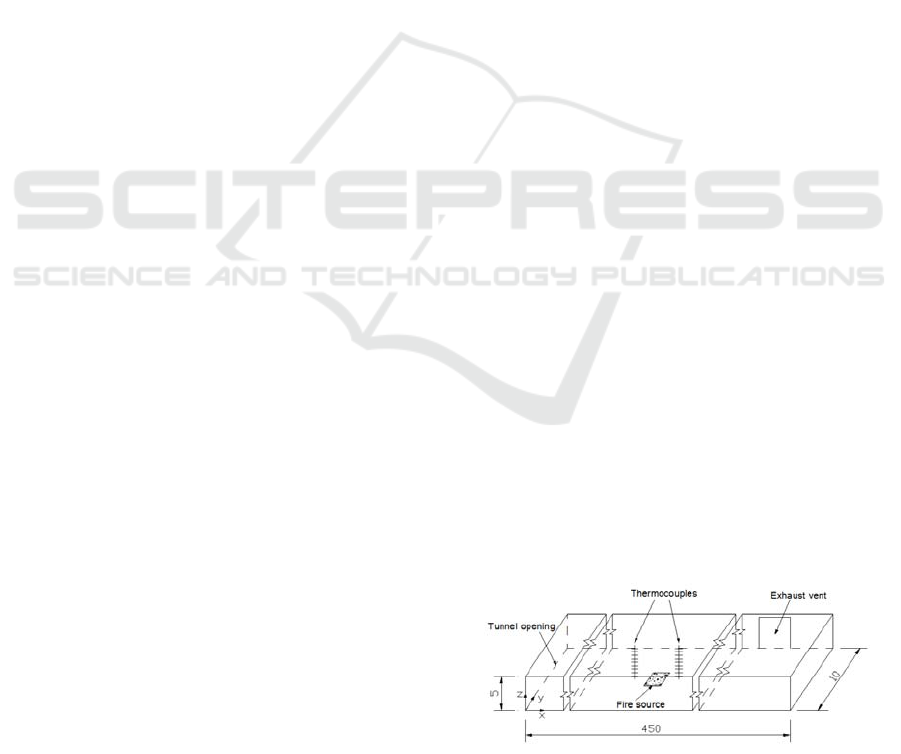
In this study, the size of tunnel in the numerical
simulation is set as 450 m × 10 m × 5 m. Propane is
used as the fuel. The size of the fire source is 10 m
× 2.6 m × 1 m and located at the center 220 m from
the left side of the tunnel. The tunnel for mechanical
smoke extraction is 130 m from the right side of the
fire source, and is set at the internal sidewall of the
tunnel. After the fire started, the smoke vent was
closed and mechanical smoke extraction began after
60 s. A specific model is shown in Figure. 1.
Figure. 1 Simulation model of the tunnel (unit:m)
Li, Y. and Cai, S.
A Numerical Simulation of Smoke Extraction in the Tunnel Sidewall.
In 3rd International Conference on Electromechanical Control Technology and Transportation (ICECTT 2018), pages 329-333
ISBN: 978-989-758-312-4
Copyright © 2018 by SCITEPRESS – Science and Technology Publications, Lda. All rights reserved
329

2.2 Monitoring Equipment
Four thermocouples and two sites for thickness
monitoring are set at the left and right sides of the
fire source, with the distance of 50 m.
Thermocouples are set at locations 50 m from the
left and right sides of the fire source, with y equal to
6 m, and are equidistantly distributed along the
vertical direction, with the interval of 0.9 m. The
highest point is 1.4 m from the ceiling. Thickness
monitoring sites are set at locations where the values
of y are equal to 6 and 8 m, respectively. At the
smoke vent, a total of 60 thickness monitoring sites
are set, with the interval along the horizontal
direction being 1 m and the interval along the
vertical direction being 0.9 m. Forty thermocouples
and 40 monitoring equipment of gas flow rate are set
with equal distances in the vertical direction. The
interval is set as 0.9 m and the distance of the highest
point is 1.4 m from the ceiling to ensure that the
temperature and velocity of the upper smoke layer
and lower air layer can be perfectly detected. A
device for monitoring mass flow rate is placed at the
right side of the fire source to cover the entire smoke
vent. The cross-section at the leftmost side of the
tunnel is set to be fully open as the air inlet during
smoke extraction.The specific layout is shown in the
following figures.
Figure. 2 Schematic diagram of the layout of the
monitoring sites for the thickness of the smoke layer
Figure. 3 Schematic diagram of the layout of the
monitoring sites for air velocity
2.3 Conditions for Numerical Simulation
The conditions for numerical simulation are listed as
follows:The numbers of each condition are 1-10;the
power of each fire source is 15MW;each ambient
temperature is 20°C;each size of smoke vent is 4.5
m × 4.5 m;each computation time is set as 600s;
and the rates of smoke extraction are 0m3/s
(NO.1)、20m3/s(NO.2)、40m3/s(NO.3)、
60m3/s(NO.4)、80m3/s(NO.5)、100m3/s(NO.6)、
120m3/s(NO.7)、140m3/s(NO.8)、160m3/s
( NO.9 ) and 180m3/s( NO.10 ) .The smoke
extraction rate in the tunnel is regarded as a variable.
Under different rates of mechanical smoke
extraction, the variations of the shape, temperature,
and thickness of the smoke layer and the Froude
number (Fr) are investigated.
3 RESULTS AND DISCUSSION
3.1 Calculation of The Output and
Efficiency of The Smoke
Extraction System
Vauquelin (2002, 2008) defined two global
parameters used to describe the performance of the
horizontal smoke extraction system quantitatively.
One parameter is the ventilation system efficiency
(VSE). The other parameter is the ventilation system
output (VSO). The expressions of these two
parameters are as follows:
VSO=q
se
/q
e
(1)
VSE=q
se
/qs (2)
where q
se
denotes the mass flow rate of
discharged smoke, q
s
denotes the mass flow rate of
generated smoke, and q
e
denotes the mass flow rate
of rated smoke extraction. As reported in the
literature (Jiang Yaqiang, 2009), under the condition
of no plugholing of the smoke layer, the content of
discharged gas at the smoke vent is all smoke. As
such, q
se
is equal to q
e
. Under this condition, VSO is
100% and the system exhibits the best performance.
When plugholing of the smoke layer occurs, q
se
becomes less than q
e
. Under this condition, VSO
represents the proportion of smoke in discharged
gas. The remaining proportion (1 − VSO) is air.
Evidently, the higher the VSO, the better the
performance of the smoke extraction system.
In this study, the smoke extraction rate is
expressed as
V
e
and the corresponding mass flow
rate is expressed as q
e
, i.e., the mass flow rate of gas
discharged through the smoke vent. The velocity of
smoke (U) passing through the monitoring section is
assumed to be distributed evenly in the horizontal
direction of the tunnel. The thickness of the smoke
layer is S
h
. Given the distance of 0.5 m from the top
of the smoke vent on the sidewall to the ceiling, the
ICECTT 2018 - 3rd International Conference on Electromechanical Control Technology and Transportation
330
true S
h
’=S
h
-0.5 is obtained. The density of the upper
smoke layer is . The width of the tunnel is denoted as
d. Then, the mass flow rate of discharged smoke is
calculated as follows:
q
se
=ρ
s
×U×S
h
’×d
(3)
Eq. (3) is substituted in Eqs. (1) and (2) to obtain
the calculation formulas of VSE and VSO, as
follows:
e
hs
q
d'SUρ
VSO
e
se
q
q
(4)
s
hs
q
d'SUρ
VSE
s
se
q
q
(5)
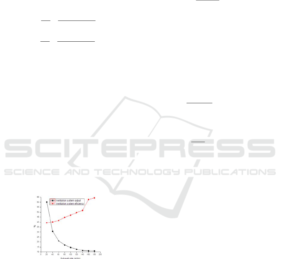
Figure. 4 shows that VSO decreases with the
increase in smoke extraction rate by using Eqs. (3),
(4), and (5). When the extraction rate is low, the total
amount of gas discharged is small, with smoke
accounting for a large proportion, i.e., VSO is large.
With the continuous increase in the smoke extraction
rate, turbulence occurs. Although the total amount of
extracted smoke also increases, VSO gradually
reduces and finally stabilizes at 11%. In contrast to
VSO, VSE increases with the increase in the smoke
extraction rate. Based on the “Code for Metro
Design”(GB, 2003), the amount of discharged smoke
in the platform and hall of the station should be
calculated as 1 m
3
/min/m
2
of the construction area.
Based on this criterion, the designed volume of
smoke extraction for the model is calculated to be 75
m
3
/s. Considering Figures.4, the optimum smoke
extraction rate for this model is 60 m
3
/s. Under this
condition, VSO is 21.14% and VSE is 41.59%.
Figure. 4 Change of performance of the smoke extraction
system with the variation of the smoke extraction rate
3.2 Analysis of The Fr for The Layering
of Smoke
In fluid mechanics, the Fr is usually employed to
describe the proportion of inertial and buoyant forces.
A larger value of the Fr indicates a stronger
dominance of inertial force (GB, 2003; Vandeleur P
H E, 1989). In this study, inertial force, being the
horizontal shear force between smoke and air, is the
dominant factor of the occurrence of mixing,
whereas buoyant force is the dominant factor in
maintaining the layering of smoke. The Fr is
expressed as follows:
2/1
int
2
s
]
ρHg
Vρ
[
Fr
(6)
where g is the acceleration of gravity;∆V is the
shear velocity ; and Hint is the height of the
interface of the smoke layer. Smoke is regarded as
ideal gas. As such, the average density can be
obtained through the conversion of the average
temperature in the equation of the state of ideal gas,
expressed as follows: PV = nRT (n = m/M). The
average temperature is obtained based on the
function T(z), which reflects the vertical distribution
of temperature. The average temperature of the
upper smoke layer is calculated as follows:
H
H
u
dzzT
HH
T
int
)(
1
int
(7)
The average temperature of the lower air layer is
calculated as follows:
int
0
int
)(
1
H
l
dzzT
H
T
(8)
The function reflecting the vertical distribution
of temperature obtained by fitting is substituted in
Eqs. (6), (7), and (8). Figures. 5 and 6 are obtained
by calculating the aforementioned equations,that
show the variation of the Fr of the smoke vent with
the change of the smoke extraction rate when the
power of the fire source is 15 MW and the linear
function fitted by using Excel. Figures. 5 and 6
show that the Fr at the smoke vent increases with
the increase in smoke extraction rate, i.e., the
shearing motion of the smoke and air layers in the
tunnel strengthens in general. As a result, mixing of
the smoke and air layers at the smoke vent is
intensified and the volume of discharged smoke
decreases because of turbulence.
A Numerical Simulation of Smoke Extraction in the Tunnel Sidewall
331
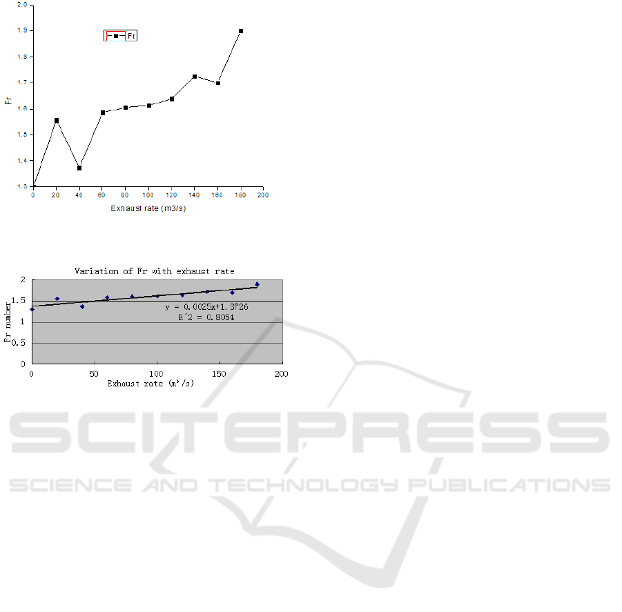
Figure. 5 Variation of the Fr with the change of the smoke
extraction rate (15 MW)
Figure. 6 Fitting of the Fr with the change of the extraction
rate (15 MW)
4 CONCLUSIONS
In this study, numerical analyses are conducted
under different smoke extraction rates to analyze the
law of smoke extraction. We obtained the following
conclusions:
(1) VSO decreases with the increase in the smoke
extraction rate, whereas VSE increases with the
increase in the smoke extraction rate.
(2) The Fr at the smoke vent increases with the
increase in the smoke extraction rate.
ACKNOWLEDGEMENTS
The authors gratefully acknowledge the support
received for this project from the Scientific Research
Foundation of Liaoning Education Department (No.
L2015096) and the Doctoral Scientific Research
Foundation of Liaoning Province (No. 201601249)
REFERENCES
Jiang Xuepeng, Yuan Yueming, et al Effect of smoke
extraction rate on the plugholing of smoke layer below
the smoke vent in tunnels[J] Journal of Safety and
Environment, 14(02): 36-40, 2014
Hu Longhua, et al Effect of the position of air inlet on the
efficiency of mechanical smoke extraction in an
underground long tunnel[J] Engineering Science, 7(5):
90-92, 2005
Jiang Yaqiang, et al Influence of transverse smoke
extraction on the characteristics of the layering of
smoke in tunnel fires[J] Engineering mechanics, 27(7):
245-250, 2010
Han Jianyun, et al Experimental investigation on the
influence of cross-section area of the shaft on natural
smoke extraction[J]. Fire Safety Science, 22(1): 32-36,
2013
Linjie Li,et al.Research on the phenomenon of
plug-holing under mechanical smoke exhaust in tunnel
fire [J]. Procedia Engineering, 2013, 62, 1112-1120
Hu L H, et al. Studies on buoyancy-driven back-layering
flow in tunnel fires[J]. Experimental Thermal and
Fluid Science,2008,32(8):1468―1483
Yasushi Oka, et al. Control of smoke flow in tunnel
fires[J]. Fire Safety Journal,1995,25:305―322
Wu Y, Bakar M Z A. Control of smoke flow in tunnel fires
using longitudinal ventilation systems-A study of the
critical velocity[J]. Fire Safety
Journal,2000,35:363―390
Vauquelin O, Telle D. Definition and experimental
evaluation of the smoke ‘confinement velocity ’in
tunnel fires[J]. Fire Safety Journal,2005,40:320―330
Futoshi Tanaka, et al. Performance validation of a hybrid
ventilation strategy comprising longitudinal and point
ventilation by a fire experiment using a model-scale
tunnel[J]. Fire Safety Journal,2015,71:287-298
Jiang Yaqiang, et al. A numerical study on the effects of
mechanical extraction rate on the plugholing of smoke
layer in a long tunnel[J] Journal of university of
science and technology of China, 39(4): 420-424,
2009
Liang Ping, Numerical simulation of the effect of smoke
channel in tunnel fires based on FDS[J] Journal of
transport science and engineering, 26(1): 50-53, 2010
Vauquelin O, Mégret O. Smoke exhaust experiments in
case of fire in a tunnel [J]. Fire Safety
Journal,2002,37(5):525-533
Olivier Vauquelin. Experimental simulations of
fire-induced smoke control in tunnels using an
“air–helium reduced scale
model”:Principle,limitations,results and future[J].
Tunneling and Underground Space Technology, 2008,
23: 171—178
Jiang Yaqiang Characteristics of smoke transport in
channels under different conditions of smoke
extraction University of science and technology of
china, 2009
GB 50157-2003. Code for metro design[S] Beijing:
Standard Press of China
ICECTT 2018 - 3rd International Conference on Electromechanical Control Technology and Transportation
332

Vandeleur P H E,et al. Numerical study of the stratifie
smoke flow in a corridor:Full-scale calculations[J].
Fire Safety Journal, 1989,14:287―302
A Numerical Simulation of Smoke Extraction in the Tunnel Sidewall
333
