
Research of Thin Film Thermocouple Based on MEMS for
Temperature Measurement on Spacecraft Surface
ZhenWei Li, ZeYuan Liu, Chang Liu and Fang Han
Beijing Institute of Spacecraft Environment Engineering, Beijing 100094, China
13502836@qq.com
Keywords: MEMS (Micro-Electro-Mechanical-Systems), thin film thermocouple, the measurement of spacecraft
surface transient temperature, physical test.
Abstract: The paper introduces the technology of MEMS and its advantages in the manufacture of aerospace sensors.
According to the requirements of spacecraft surface temperature measurement, a K-type (NiCr/NiSi) thin
film thermocouple is designed. The graphic process design of thin film thermocouple is studied, including
thermal junction and thin film lead wires. The test shows that the response time of the thin film
thermocouple is shorter and the relative error is smaller compared with the traditional thermocouple.
1 INTRODUCTION
The MEMS (Micro-Electro-Mechanical-System) is
based on the micron/nanometre technology, and was
applied to the design, processing, manufacturing,
measurement and control of micron/nanometre
materials. It’s an intelligent extension of integrated
circuit technology. The MEMS has the advantages
of miniaturization, integration, low energy
consumption, low cost, high accuracy, long life and
dynamic properties(Zhu,2013). With the above
advantages, the MEMS becomes the ideal device in
space application field. In the future, the space
exploration will focus on the cost and goal of task.
In order to save cost, the future trend will be the
MEMS devices replace the heavy weight devices on
the space carrier, the actual loads on the
communication and navigation platform.
Furthermore, it will replace the complete subsystems,
such as attitude sensor, attitude controller, phased-
array antenna, earth sensor and optical switch.
Compared with the traditional solutions, the size and
quality of MEMS devices can be significantly
decreased. Some of the MEMS devices(Wu, 2012)
which have been used in space are displayed in
Table 1.
Table 1: The MEMS devices used in space and its
technical maturity.
MEMS device
name
Flight mission
Technical
maturity
Accelerometers
, gyroscopes
NASA regular flight High-level
Pressure senso
r
Rocket normal fligh
t
High-level
Magnetomete
r
Cube satellite fligh
t
High-level
Atomic force mi
cro-scope
The "Phoenix" mission
of NASA in 2008
Advanced-
level
Solar sensor
The "Delfi 3C" mission
in 2008
Advanced-
level
Microfluidic
senso
r
The "GeneSat" satellite
mission of NASA
Middle-
level
Bolometer
The "Planck" mission of
ESA in 2009
Middle-
level
Thermal
controller
The task of "Space
Technology 5"of NASA
in2006
Middle-
level
Micro optical
electromechanic
al syste
m
Used in Jame Webb
Space Telescope in 2013
Intermediat
e-level
With the rapid development of deep space
exploration, hypersonic vehicles and space shuttle
vehicles in China, the transient temperature
measurement of the spacecraft surface is better
required(Zhang,2013). Especially, in the process of
returnable spacecraft re-entry flight, the
aerodynamic heat effect of high speed friction will
make the temperature of spacecraft surface rise
fast(Manoj,2015). The surface temperature can
better reflect the thermal characteristics of the
spacecraft and its structures. It also can provide the
reference data for the verification of spacecraft's
522
Li, Z., Liu, Z., Liu, C. and Han, F.
Research of Thin Film Thermocouple Based on MEMS for Temperature Measurement on Spacecraft Surface.
In 3rd International Conference on Electromechanical Control Technology and Transportation (ICECTT 2018), pages 522-528
ISBN: 978-989-758-312-4
Copyright © 2018 by SCITEPRESS – Science and Technology Publications, Lda. All rights reserved

thermal protection system. At present, the ordinary
thermocouples were generally used to measure the
surface temperature of spacecraft during its thermal
test and flight. However, for the hypersonic and
space shuttle spacecraft, the surface temperature is
changed sharply. Due to the structure, heat capacity
and installation mode of the ordinary thermocouples,
the measurement results were obviously hysteresis
and inaccurately. It can’t meet the measurement
requirements of the spacecraft surface transient high
temperature.
To solve the above problems, the MEMS process
of thin film thermocouples is researched in this
paper, which can be used to measure the spacecraft
surface transient high temperature. In present, the
temperature sensor based on thin film thermocouple
has been used in the measurement of the bullet
ejected bore, the wall of internal-combustion engine,
the heat flux distribution of the laser beam, and the
working cutting tool successfully(Zhao,2012).
However, due to the special structure of spacecraft,
the thin film of thermocouple can’t be pasted on the
surface of test object directly. Therefore, the needle-
type structure of thin film thermocouple is proposed
in this paper. The high temperature resistant ceramic
material is selected as the structure substrate and K-
type material is selected as thermoelectric material
for this type of thermocouple. Then, the thin film
thermocouple was prepared on the structure
substrate by magnetron sputtering technology. The
thickness of this thermocouple’s thermal junction is
micron scale, and its capacity is much smaller than
the traditional thermocouple. It can be effectively
fitted to the surface of the test object, and the
transient temperature up to 800℃ is measured
quickly and accurately. These properties make the
sensor better meet the measurement requirements of
the hypersonic vehicles and space shuttle vehicles.
2 WORKING PRINCIPLE AND
STRUCTURE DESIGN OF THIN
FILM THERMOCOUPLE
In 1821, the German physicist Thomas Johann
Seebeck found the thermocouple phenomenon,
which describes that the junction of two different
materials can generate voltage with the temperature
changing. For the same type of thermocouple, the
thermoelectric potential generated by thermocouple
is proportional to the temperature difference
between two thermal junctions. The relationship
between the thermoelectric potential and
temperature difference is described in equation (1).
ΔV=α
s
*ΔT (1)
In equation (1), the ΔV is the thermoelectric
potential generated by thermocouple, the ΔT is the
temperature difference between two thermal
junctions, and the α
s
is Seebeck coefficient, whose
unit is μV/K.
In the long term industrial practice, several
standard thermocouples have been gradually formed,
such as B-type (PtRh30-PtRh6) thermocouple, S-
type (PtRhl0-Pt) thermocouple, R-type (PtRhl3-Pt)
thermocouple and K-type (NiCr-NiSi)
thermocouple. These thermocouples are different at
thermoelectric material. In consideration of the
working temperature range, the measurement
accuracy and the economic cost, this paper selects
the K-type thermoelectric material which conforms
to the national standard to research the MEMS film
technology.
In order to fit the actual conditions of the
transient temperature measurement on spacecraft
surface, the style of thin film thermocouple structure
was designed as needle-like. As shown in Figure 1,
the thermocouple structure substrate is divided into
the base head and the base tailstock. First, Al
2
O
3
insulation film was deposited on the surface of the
thermocouple substrate that the material is high
temperature resistant ceramic material. Then, the K-
type thermocouple thin film was deposited on the
top of substrate base head by magnetron sputtering
technology. Finally, the Al
2
O
3
insulation film is
deposited on the thermocouple film. This insulation
film can protect thermocouple film from falling off
and breaking, caused by friction, scour, impact and
corrosion. At the same time, it can also provide the
well electrical insulation and physical protection for
thermocouple film.
Figure 1: The structure diagram of needle-type thin film
thermocouple.
The thermal junction of thermoelectric material
is located at the top of base structure’s head. As
shown in Figure 2, the NiCr film and NiSi film were
Research of Thin Film Thermocouple Based on MEMS for Temperature Measurement on Spacecraft Surface
523
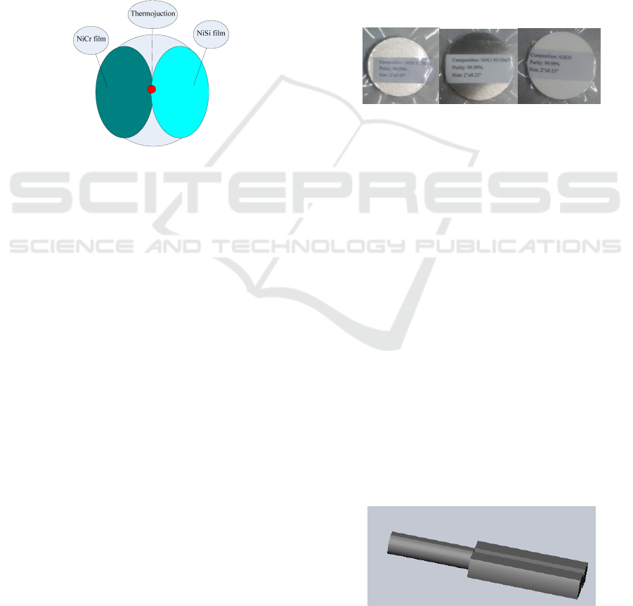
prepared on the left and right semicircular surfaces
on the top of base head by the magnetron sputtering
technology. The thermal junction is the core of the
sensor. The thickness of the thermocouple film is
about 2μm. The diameter of the isothermal surface is
50 times more than thermocouple film’s thickness,
while, the geometric area of thermal junction is
much less than the isothermal surface. Therefore, the
specific heat capacity of the thermal junction is
much smaller than that of the traditional
thermocouples. It can achieve the measurement of
transient temperature easily. The thermal junction of
the thin film thermocouple is good performances.
But, the preparation process of the thin film
thermocoupleis difficult.
Figure 2: The thermal junction diagram of thin film
thermocouple.
3 THE FABRICATION PROCESS
OF THERMOCOUPLE
The k-type thin film thermocouple studied in this
paper is processed by MEMS process. The MEMS
microprocessing technology is an extension of
traditional microelectronics technology. In the
substrate selection from the traditional silicon
material, expanded to ceramics, glass, plastic and
other materials. MEMS microprocessing technology
enables the chip processing method from 2D to 3D,
through electroplating, mold, laser, corrosion and
other processes. A series of MEMS processes, such
as photolithography, stripping and sputtering, are
used during the processing of k-type film
thermocouples. The substrate of thermocouple is
nonplanar substrate, with greatly processing
difficulty. The special fixture is designed in this
paper, and the fabrication of MEMS process, such as
photolithography and sputtering of 3D unit, is
realized.
3.1Target material
The electrode materials of the k-type thin film
thermocouple are prepared by sputtering, and the
sputtering equipment is KJLC LAB18. Sputtering
particles of energy (ions, neutral atoms or
molecules), such as argon ions, are used to bombard
the target surface. Atoms and molecules near the
target surface will get enough energy to escape from
the target surface, and then deposit on the substrate
of thermocouple. The purity of target material will
affect the composition of the thermocouple electrode
and the temperature measurement precision of the
thermocouple. In this paper, the targets of Ni
90
Cr
10,
Ni
97
Si
3
and Al
2
O
3
with purity of 99.99% were
prepared according to the atomic weight ratio, which
were shown in Figure 3.
Figure 3: Sputtering targets
3.2 The technology process
Fabrication process of needle-type thin film
thermocouple includes ceramic substrate production,
lead wire production, thermal junction production,
and the encapsulation of the lead terminal etc. In the
process, each step is carried out in order.
3.2.1 Selection of the substrate material
The substrate is the basic component of the thin film
thermocouple structure. Because the maximum
temperature range of the film thermocouple reaches
800℃, it is necessary for the substrate material to
have a high temperature resistance. In addition, in
order to avoid the influence of the thermocouple
temperature from the substrate, that is required to
having low thermal conductivity for the substrate.
This paper uses the Al
2
O
3
ceramic with high heat
resistance and low thermal conductivity as substrate
material. As shown in Figure 4 as the substrate
structure.
Figure 4: The structure of substrate
ICECTT 2018 - 3rd International Conference on Electromechanical Control Technology and Transportation
524

3.2.2 The lead terminal making
According to the thermocouple homogeneous
conductor's law, if the third material in the
production of lead terminals was inducted, it may
cause the thermal potential of two leads different,
and then cause the measurement errors. In this
paper, the electrode leads are made by the same
target materials as the two thermoelectric materials
of the thermocouple, and then bonded to the grooves
on the side of the base with high temperature
ceramic glue. The surface of the electrode leads
needs to be planed and polished. As shown in Figure
5 as the lead terminal making.
Figure 5: The lead terminal making
3.2.3 Preparation of lead wire
The commonly used methods for making the thin
film lead of thermocouple are peeling and etching
respectively. Special aluminum foil tape is used as
the mask in the peeling method, and the design
pattern of the thin film lead is transfered to the mask
by stamping or laser etching process. Using the NiCr
and NiSi target sputtering, film thickness is 1μm.
The mask is removed to form thermal electrode film
pattern. However, the change of the temperature in
the sputtering process causes the change of the
adhesive force between the mask and the substrate,
resulting in the distortion of the mask pattern.
In order to solve the above problems, this paper
uses laser etching method to make thin film. The
surface of the ceramic substrate is covered by
sputtering thickness of 1μm NiCr/NiSi film. The
film parameters design is directly input into the laser
controller to control the movement of the laser spot,
and the excess film is melted away. The etching
laser is produced by a 1064nm wavelength fiber
laser with a moving precision of 1μm, which can
ensure the high precision of lead figure. As shown in
Figure 6, the width of the film lead is designed to be
250μm, and the measured width is 254.30μm.
Figure 6: Thin film wire
3.2.4 Preparation of the thermal junction
The thermal junction is the most important part of
the thermocouple measurement circuit, which is
directly contacted with the surface of the
thermometric object. The heat capacity of the
thermal junction is very small, and it can quickly
reach the same temperature as the surface of the
thermometric object. By measuring the
thermoelectric power signal produced by the
Seebeck effect, surface temperature can be
calculated. As we can see from Figure 2, the region
of the interaction between NiCr film and NiSi film
forms a thermal junction, with a diameter of 200μm
and a thickness of 2μm. The mechanical mask and
exposure mask methods were studied and analyzed
in this paper before preparing the thermal junction.
If the mechanical mask method is adopted, the
SUS304 stainless steel sheet will be handled
according to WEDM process of making the mask, as
shown in Figure 7. Due to the edge roughness of the
mechanical mask relatively large, the figure of the
thermal junction is not regular enough.
Figure 7: The mechanical mask
In order to further insure the accuracy of the
graphics, a special exposure mask method is
developed in this paper. First, the design
diagram is
transferred (copied) to the film. Then, photosensitive
ink or hot pressing dry film was coated on the top of
the ceramic substrate. The film mask is placed on
the top of ceramic column, and then exposed with
UV lamp. It is melted into the developing liquid.
Then the top shape has been transferred to the top of
ceramic column. After the sputtering is completed,
the ceramic column is put into the stripping solution
Research of Thin Film Thermocouple Based on MEMS for Temperature Measurement on Spacecraft Surface
525

or acetone solution to dissolve the ink or dry film.
Finally, as shown in Figure 9, only the thermal
junction film is left on the top of the ceramic.
Figure 8: Thermocouple junction design
4 PHYSICAL VERIFICATION AND
RESULT ANALYSIS
In order to verify the overall performance of the thin
film thermocouple which was designed in this paper,
a thermocouple performance testing system was
developed firstly(Li,2017). As shown in Figure 9,
the system consists of control computer, measuring
instrument, programmable power supply, infrared
lamp array, copper plate of constant temperature and
graphite carpet etc. During the actual test, 8 K-type
ordinary thermocouples and 2 K-type needle thin
film thermocouples were installed equably
on
φ
200mm circle on the copper plate. The
temperature of the copper plate must maintain
constant in order to ensure that all thermocouples
were in an uniform temperature field. The copper
plate was heated by the infrared lamp array, and its
target temperature was set as the average
temperature value of 8 ordinary thermocouples. The
thermoelectric potentials of ordinary thermocouples
and needle thin film thermocouples under the same
temperature field were read, and then converted into
the temperature values. Comparison and analysis of
the temperature measurement values between thin
film thermocouple and ordinary thermocouple, the
results of two thermocouples fit well, we can
conclude the measurement performance of the film
thermocouple under the conditions of high
temperature impact and transient temperature was
verified.
Measurement and
control computer
Programmable
power supply
Data acquisition
instrument
Infrared
lamp array
Constant
temperature
copperplate
Thin film
thermocouple
Graphite felt
Figure 9: Performance test system for thin-film
thermocouple.
In this paper, eight K-style ordinary
thermocouples were named by 1# to 8#,and two
K-type needle thin film thermocouples were named
by 9# to 10#. In order to verify up to 800℃working
temperature of the thin film thermocouple , the
copper plate for the performance test system was
heated up to 850℃. The excess of 50℃is used to
verify the reliability of the film thermocouple. The
test results of measurement points were shown in
Figure 10 and Figure 11.
a: global curve
b: partial enlarged curve
Figure 10: Temperatures of the copper plate and needle
thin film thermocouples
The average temperature value of eight ordinary
thermocouples and two thin film thermocouples
were shown in the Figure 10. We could see from
figure 10 that the copper plate was begun to heated
at about 107min. And then, the temperature values
of all thermocouples increased rapidly, and reached
about 850 ℃ at about 127min. Among them, the
average temperature value of eight ordinary
thermocouples rose from 29.6℃ to 850.1℃ in 20
minutes, and its average temperature rise rate was
100 150 200 250 300
0
100
200
300
400
500
600
700
800
Time/min
Temperature/
the average from 1# to 8#
9#
10#
160 165 170 175
555
560
565
570
575
Time/min
Temperature/
the average from 1# to 8#
9#
10#
ICECTT 2018 - 3rd International Conference on Electromechanical Control Technology and Transportation
526

41.2℃/min, and its maximum temperature rise rate
was 78.8 ℃/min. The temperature of needle thin
film thermocouples rose from 29.6℃ to 853.2 ℃ in
20 minutes, and its average temperature rise rate was
41.2 ℃/min, and its maximum temperature rise rate
was 78.9 ℃/min.
a: absolute errors
b: relative errors
Figure 11: Temperature measurement errors of thin-film
thermocouples
For the purpose of analysis of the validity and
accuracy of temperature value for the needle thin
film thermocouples, the temperature values of 9#
and 10# thin film thermocouple were compared with
the actual value of the copper plate (the average
temperature of eight ordinary thermocouples). The
absolute error and relative error of 9# and 10# thin
film thermocouple were shown in Figure 11. We can
see that the film thermocouple can response the
temperature change of the copper plate excellently,
and the response time is short. Among them, the
maximum absolute error of the needle film
thermocouple is 3.67 ℃, and the maximum relative
error is 0.47%.
Based on the analysis of experimental results, it
is shown that the thin film thermocouple based on
MEMS technology has a smaller heat capacity, and
shoter response time than the ordinary
thermocouple. Furthermore, the maximum absolute
error of the thin film thermocouple can be less then
±4 ℃, and its relative error is less than 0.5%. The
performance of the thin film thermocouple meets
well the design goals.
5 CONCLUSIONS
In this paper, a needle thin film thermocouple for the
measurement of high transient temperature on the
surfaces of hypersonic vehicle and shuttle vehicle
has been researched. The substrate of the thin film
thermocouple is made of high temperature resistant
ceramic material, and the K-type thermocouple film
was deposited on the surface of base top by
magnetron sputtering technology. The fabrication
process of the thermocouple film lead terminal and
thermal junctions were mainly studied and
optimized. The performance of the thin film
thermocouple was verified by the test system. The
test results show that the needle thin film
thermocouple owns excellent performance,
including short response time, and the relative error
of less than 0.5%. It can meet the measurement
requirements in the field of transient temperature on
surfaces of hypersonic vehicle and shuttle vehicle
completely.
ACKNOWLEDGEMENTS
The work is supported by key project of the advance
research field fund provided by the Ministry of
Equipment Development (NO. 6140923020301).
REFERENCES
Li Z W, et al. 2017. Development of thin-film
thermocouple for measuring transient temperature of
spacecraft surfaces. Spacecraft Environment
Engineering.
Manoj K S and Dewal M L. 2015. Simulation of thin film
thermocouple for high temperature measurement
applicable to missiles. Defence Science Journal.
0 50 100 150 200 250 300 350
-0.5
0
0.5
1
1.5
2
2.5
3
3.5
4
Time/min
Absolute errors/
9#
10#
0 50 100 150 200 250 300 350
-0.2
-0.1
0
0.1
0.2
0.3
0.4
0.5
0.6
Time/min
Relative errors/%
9#
10#
Research of Thin Film Thermocouple Based on MEMS for Temperature Measurement on Spacecraft Surface
527

Wu X D. 2012. Application and prospects of MEMS
devices for space. Micronanoelectronic Technology.
Zhang S Y, Ma Y H, Zhao X J. 2013. The experimental
study of heat-flux identification technology for
hypersonic aerothermodynamics[J]. Journal of
Experiments in Fluid Mechanics.
Zhao Y S and Yang L H. 2012. Research progress of thin
film thermocouple temperature sensor. Transducer
and Microsystem Technologies.
Zhu X X and Zhou X W. 2013. Temperature sensor.
Electronic Test.
ICECTT 2018 - 3rd International Conference on Electromechanical Control Technology and Transportation
528
