
Research on Application of Shutter Flow Regulating Valve in
Aerodynamic Performance Test of Fan
Shihui Xu
1
, Shuiying Zheng
2
, Li Li
1
, Rui Ma
2
, Jingdong Mai
1
and Xiaoyan Tian
1
1
China North Vehicle Research Institute, Beijing , China
2
Institute of Chemical Machinery Zhejiang University, Hangzhou, China
Keywords:
Aerodynamic performance test of fan, shutter flow regulating valve, united type, divided type.
Abstract: Taking DN700 shutter flow regulating valve as research object,the CFD model of vehicle cooling fan
aerodynamic performance test system is established by using Gambit and Fluent software. Through analysis
of pressure field and velocity field in duct, the application of shutter flow regulating valve in aerodynamic
performance test of fan and influence of different types of fans on performance test were discussed. The
results indicated that shutter flow regulating valves can be substituted for traditional sticking paper in
aerodynamic performance tests of fan. These make it possible to automatically control air flow of operating
state point and sample for performance test of fan. These researches provide a reference for the automation
of aerodynamic performance test for vehicle fans.
1 INTRODUCTION
C-type experimental set-up specified in GB/T
1236-2000(2001) or ISO 5801:2007 often used in
aerodynamic performance tests of cooling fan in
vehicle. During the process of these tests, people
usually stick a paste on the loading mesh of test
pipeline to load the inlet manifold of fan to adjust
flow quantity. But there are some shortcomings:
selection of test mode point is not controlled due to
stochastic of paste; there is high risk of test person
because of exposure to test environment of rotating
part in manual stick method. They can be overcome
by using shutter flow regulating valve to adjust flow
quantity, and sampling control test mode point to
realize automatic aerodynamic performance test of
fan.
Shutter Flow regulating valve often used in
wind-tunnel tests, when the diameter of pipeline is
small, it can’t be used in fan test. Because if use
shutter flow regulating valves to adjust flow quantity
in small-diameter pipeline, it will guide downstream
air flow and result in unevenness flow. And the test
will be invalid if can’t get rid of it after the air flow
passing through the rectifying gate.
Familiar shutter flow regulating valves can be
divided into united opening type and divided
opening type, see figure 1. When the valves change,
all of the blades of united opening valves will rotate
in the same direction and the blades maintain
parallel to each other, but the rotation of adjacent
blades of divided opening type is opposite. In this
paper, the shutter flow regulating valves used in
pipeline of fan test is numerically simulated(Li
Jianfeng, 2006; Chang Zezhou, 2009; Liu Song,
2009) by Fluent, include united opening type and
divided opening type, and the influence on airflow is
analyzed and contracted to confirm whether it can
be used in aerodynamic performance tests of fan or
not.
606
Xu, S., Zheng, S., Li, L., Ma, R., Mai, J. and Tian, X.
Research on Application of Shutter Flow Regulating Valve in Aerodynamic Performance Test of Fan.
In 3rd International Conference on Electromechanical Control Technology and Transportation (ICECTT 2018), pages 606-611
ISBN: 978-989-758-312-4
Copyright © 2018 by SCITEPRESS – Science and Technology Publications, Lda. All r ights reserved
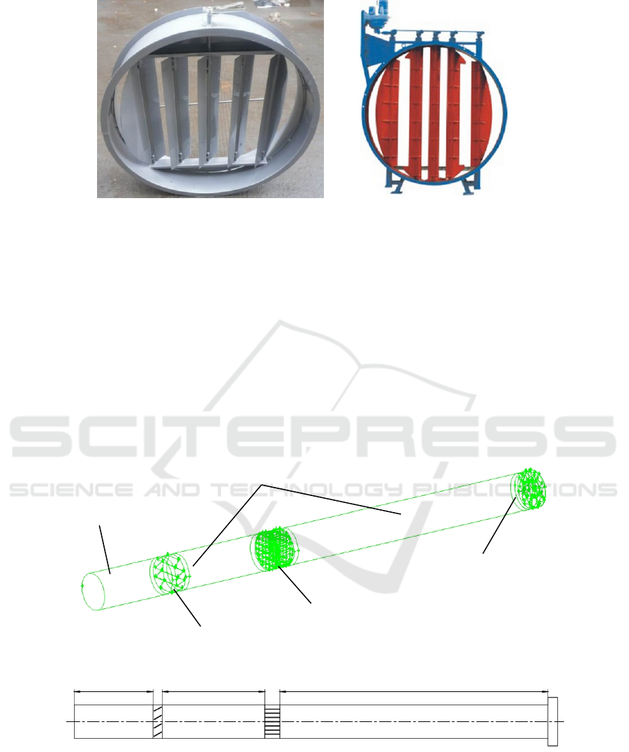
(a) united opening type (b) divided opening type
Fig. 1: shutter flow regulating valve
2 VA LV E A N D DUCT
MODELLING
2.1 Geometry model
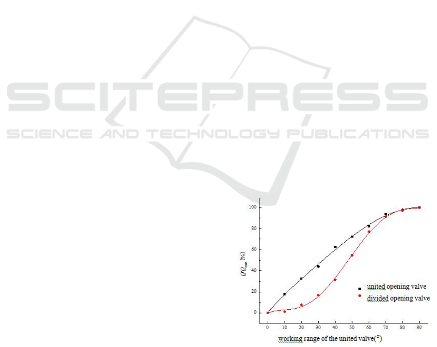
Object is a pipeline that inner diameter is 700mm,
calculated model is shown in Figure 2.
Calculate area is divided into inlet section and
impeller area. Inlet section is flow field area
between pipeline inlet and fan inlet, include inlet
flatness tube segment, shutter flow regulating valve,
fairing screen and pipeline public segment, the
pressure hole on pipe wall is ignored during the
modeling. The single axial fan used have no guide
vane, parameter as follows: rim diameter 320mm,
outer diameter 690mm, width 200mm, 8 vans
uniformly distribute around, rating rev is 1750r/min.
Fig. 2: calculate area model
There are 4 vanes in a shutter flow regulating
valve, which is 175mm high and 4mm thickness.
To research the influence of united opening type
and divided opening type valves in different opening
inlet flatness tube segment
flow regulating valve
pipeline public segment
rectifier grid
tested fan
Research on Application of Shutter Flow Regulating Valve in Aerodynamic Performance Test of Fan
607
on test system flow field, 9 calculated model of
different opening are established in 10°, 20°, 30°,
40°,50°,60°,70°,80°,90°.
2.2 Mesh model
Impeller area: the edge of tetrahedron mesh is 8mm
which compartmentalize the area, and the
dimensional function is further encrypted for the
area of blade tip clearance. The number of grid cells
is about 1.2 million.
Inlet section: because the flow field near the flow
regulating valve and rectifier grid is rather complex,
it is necessary to divide the flow field with dense
mesh in order to ensure calculation higher accuracy.
The tetrahedron mesh and the hexahedron mesh with
the edge of 10 mm are used to divide the meshes
respectively. Due to its regular shape and low mesh
quality, cylindrical pipes are divided into hexahedron
grids with long edges in order to save computational
resources. The total number of grids in the whole
inlet section is about 3 million.
3 CALCULATION PROCESS
AND RESULTS
3.1 Calculation method and boundary
condition
The air is regarded as incompressible fluid, there is
no heat exchange in the flow, and the energy
conservation equation is not taken into account. The
gas is steady flow, the constant calculation is
adopted, and the influence of gravity is ignored. The
turbulent model adopts a standard k - ε model , the
near wall is applied with a standard wall function ,
and the pressure velocity is coupled with SIMPLE
algorithm , momentum equation , turbulent kinetic
energy and turbulent dissipation phase . The
convergence criterion is defined as the residual less
than 1 × 10
- 4
for all monitoring items.
The inlet boundary condition is set as the
pressure inlet , and the inlet total pressure is defined
to be zero relative to the atmospheric pressure ; the
outlet boundary condition is set to the pressure
outlet , and the outlet static pressure is defined to be
zero relative to the atmospheric pressure ; and the
solid wall adopts the non - slip boundary condition .
3.2 Analysis of CFD flow Field affected
by Valve to Air duct
3.2.1 Flux characteristics of Valve
The flux percentage of the fan varies with the
opening of the valve blade as shown in Fig. 3. It can
be seen that the flux characteristics of the united
opening valve are close to that of the fast opening
valve and the flux is bigger when the opening of the
valve is small. When the blade opening is 70 °, the
fan flux rate is close to the maximum value, and then
the flux rate just vary a little while the opening
degree increases,.
The variation of flux characteristics of divided
opening valve showed different rules, with the
increase of opening, the rate of change with flux of
the fan increased first and then decreased. When the
opening is less than 30 °, fan flow changes slowly
with the increase of opening; when the blade
opening between 30 °and 70 °, flux change from the
maximum of 20% increases to 90% rapidly with the
increase of opening fan, the rate of change with flow
is bigger than united opening valve; when the
opening increasing further, the rate of change
becomes very small, the flow characteristics now is
similar to that of united opening valve. At the same
time it can be seen that the flow of divided opening
type is always less than that of united opening type
at same opening of valve.
The flow regulating valve is installed in the
pipeline, hoping to get a linear working
characteristic, but the two kinds of valves do not
have a good linearity. The working range of the
united valve is 0 ° -70 °, and the working range of
the divided valve is 20 °-70 °.
Fig.3simulated characteristic curve of shutter flow
regulating valves
The full - pressure efficiency of the fan is shown
ICECTT 2018 - 3rd International Conference on Electromechanical Control Technology and Transportation
608
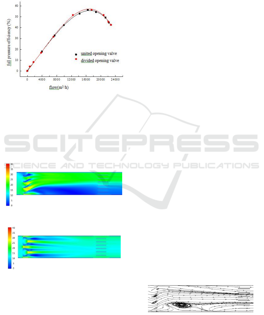
in Fig. 4. It can be found that the two curves are
basically the same shape, especially in the small
flow area and the large flow area , this two curves
are same, which indicate the two valves can be used
to obtain the more accurate curve of the fan
performance .
Fig. 4 simulated characteristic curve of fan
The calculated flow rate of rating point of the fan
is18000m
3
/h, and the corresponding valve opening is
approximately 60 °, so the further analysis is carried
out with the valve blade opening of 60°.
3.2.2 Speed distribution
(a) united opening type
(b) divided opening type
Fig.5 pipeline velocity chart when valve opening is 60°
When the valve opening is 60 °, the shutter flow
regulating valve and the flow velocity near the gate
distribution are shown in Figure 5.From Figure 5
(a)we can see: when united valve blade along the
diversion effect of the gas flow through the valve
strands of the same direction deflection occurs, and
converge on top of the pipeline, resulting in velocity
of upper air significantly greater than the downside.
The average speed of upper airflow is 20.5m/s in the
pipe, and the velocity of lower pipe flow is less than
5m/s, so two blocks form a clear boundary.
At the same opening, effect of united valve on
the flow direction of deflection is much weaker.
From figure 5 (b) we can see: through the valve gap
between the blades the airflow forma high-speed jet,
these high speed jet flow along the axial direction
and converge at the head of rectifying grids. The
velocity distribution of downstream flow field is
uniform and the average speed is about 12m/s.
3.2.3 Streamline and turbulent kinetic
energy
Figure 6 and Figure 7 show the kinetic energy
distribution of streamline and turbulent near the flow
regulating valve and the rectifier grid. It can be seen
that due to the strong shear action of high-speed jet
and low-speed fluid at leeward side, fluid eddies at
the leeward side of leaves, resulting in a significant
increase in the turbulent kinetic energy.
For the united opening valve, the three vortex
areas above is intensity but range over a small field,
the bottom vortex area is weak but range over a wide
field. The mainstream converged by three jets shear
each other with low-speed fluid lower in the pipeline,
to form a larger vortex, resulting in disordered flow
between the valve and rectification grid. The
nephogram shows that the turbulent kinetic energy
lower in the pipeline is 15 times more than the lower,
at the same time we can see: the turbulent kinetic
energy decreased significantly after passing through
rectifying grid, the turbulent kinetic energy
downstream in rectifying grid is within 5m
2
/s
2
,
indicating the rectifying grid can eliminate
secondary flow and combing the flow field
effectively.
The vortex area of divided opening valve is
concentrated on the rear part of the two central
blades, and the incidence is small. When the valve
downstream pass through about 1.5D, the turbulent
kinetic energy of the flow field decreases rapidly,
and the velocity distribution is very uniform at the
grid.
(a) united opening type
m/s
m/s
Research on Application of Shutter Flow Regulating Valve in Aerodynamic Performance Test of Fan
609
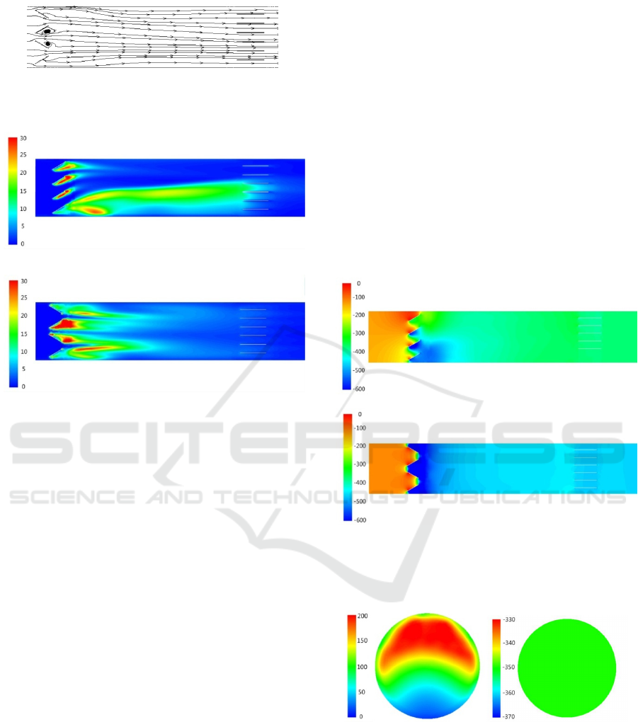
(b) divided opening type
Fig.6 streamline of pipeline at 60 ° opening
(a)united opening type
(b)divided opening type
Fig.7 turbulent kinetic energy nephogram of pipeline at 60 °
opening
3.2.4 Pressure distribution
Figure 8 shows the hydrostatic distribution of shutter
flow regulating valve and the flow field near the
rectifying grid. The valve blade blocks the fluid
resulting in the increased static pressure of blade
windward side, static pressure energy translate into
dynamic pressure which forming a low pressure area
due to the vortex exits in leeward side of vanes. For
the united opening valve low pressure area at the
bottom range over a wide field, in the downstream
within about 1D of the valve the pressure gradient of
pipe is obvious, and then the flow pressure
distribution tends to be uniform. The static pressure
distribution of divided opening valve is symmetrical
about the central axis, the low pressure area range
over a wide field and values small, after the low
pressure area the static pressure increase gradually,
static pressure uniformly distributed at the rectifier
grid. It can be seen that the distribution of low
pressure and vortex area is consistent.
Figure 9 and figure 10 are dynamic pressure and
static pressure nephogram of static pressure
measuring section using two kinds of valves. It can
be seen that due to the downstream flow field of
rectifying grids is flat, no matter which kind of valve
we use, static pressure distribution of static pressure
measurement section are uniform. The main
influence of the valve is the dynamic pressure, when
using the united opening valve, the dynamic pressure
measured on section is far greater than the lower side,
and this is consistent with the velocity distribution in
the pipe; when using divided opening valve, the
dynamic pressure distribution on the section is
equality. When using C type test device for fan
aerodynamic performance test, dynamic pressure of
fan is calculated by flow, gas density and
cross-sectional area rather than measurement directly,
so the uneven distribution does not affect the
dynamic pressure in fan test, but this will directly
affect the accuracy of static measurement.
(a) united opening type
(b)divided opening type
Fig.8 static pressure nephogram of pipeline at 60 ° opening
Fig.9 dynamic pressure and static pressure distribution of
static pressure measurement section (with united opening
flow regulating valve)
m
2
/s
2
m
2
/s
2
Pa
Pa
Pa
Pa
ICECTT 2018 - 3rd International Conference on Electromechanical Control Technology and Transportation
610

Fig.10 dynamic pressure and static pressure distribution of
static pressure measurement section(with divided opening
flow regulating valve)
4 CONCLUSIONS
By simulating the flow characteristics of valves and
the internal flow field of united opening valve and
divided opening shutter flow regulating valves in
different opening degrees, the following conclusions
can be drawn:
1)Both valves can elicit accurate performance
curve of fan. It basically meets the requirement of
using C type test device specified in GB/T
1236-2000 or ISO 5801: 2007 in aerodynamic
performance test of fans.
2) The flow range of the fan is allowed from 8
000 m
3
/ h to 20 000 m
3
/ h, and the opening range of
the flow regulating valve is 30 °-70 °. Within this
range, the flow characteristics of the two valves is
nearly linearity, which meets the need of sampling
control of test operating conditions.
3) The deflecting effect of the united opening
valve on the airflow direction is obvious, which
leads to a big velocity gradient in the downstream
flow field, and a large scale vortex will be formed in
the downstream of the valve due to the strong shear
action of both sides of the airflow. So the flow loss is
caused and the influence range of vortex is
increasing with the decrease of opening. The
velocity distribution of downstream flow field in
divided opening valve is relatively uniform. There is
a vortex region with little influence only in the rear
of the blade. Therefore, in the point of reducing
energy loss, the divided opening valve is superior.
4)The static pressure distributions of the static
pressure measurement section of the two valves are
uniform, but the dynamic pressure distribution is
quite different. When the united opening valves
work, the aerodynamic pressure above the cross
section is much larger than that on the lower side,
which is consistent with the velocity distribution in
the pipeline. The dynamic pressure distribution on
the cross section is uniform when adopting the
divided opening valve. The uniformity of the
dynamic pressure distribution will affect the
accuracy of the static pressure measurement directly.
Therefore, divided opening valve is superior
considered measurement accuracy.
In summary, when using C type test device
specified in GB/T 1236-2000 or ISO 5801: 2007 in
fan aerodynamic performance tests, the inlet duct
can be loaded by the divided opening shutter flow
regulating valve instead of the manual sticker
method in order to realize the sampling control of
mode point and test automation.
ACKNOWLEDGEMENTS
Authors would like to acknowledge National key
research and development plan of China (Grant No.
2016YFC0801204)
REFERENCES
GB/T 1236-2000 Industrial fans - Performance testing
using standardized airways[S]. Beijing:Standards
Press of China,2001.
ISO 5801:2007 Industrial fans——Performance testing
using standardized airways
Li Jianfeng,LV Jun-fu. Simulation of Air Flow in a
Blower[J]. Fluid Machinery,2006,34(4):11-13.
Chang Zezhou,LuoHao. Application of CFD Software in
the Design of Fan[J]. Compressor, Blower and Fan
Technology,2009(2),60-64.
Liu Song,Wu Shufu,Zhang Lixiang. Discussion of 3-D
Modeling for Axial-flow Fan and Its Internal Flow
Field Based on CFD[J]. Compressor, Blower and Fan
Technology,2009(2),16-19.
Pa Pa
Research on Application of Shutter Flow Regulating Valve in Aerodynamic Performance Test of Fan
611
