
Agile Smart-device based Multi-factor Authentication for Modern
Identity Management Systems
Thomas Lenz and Vesna Krnjic
Egovernment Innovation Center - Austria, Inffeldgasse 16a, Graz, Austria
Keywords:
Multi-factor, Authentication, Distributed Signatures, Identification, Identity Management, Agile, Provable.
Abstract:
Identification and authentication are essential processes in various areas of applications. While these processes
are widely described and examined in respect to Web applications that are used on personal computers, the
situation is more demanding on smart or mobile devices, as these devices provide other interfaces and have
a different user behavior. Additionally, the smart or mobile technology sector has a continuous enhancement
that results in no stable technology over the years. Consequently, new usable, agile, and secure methods
become necessary to bring identification and secure authentication on smart or mobile platforms. Several
proposals are published that should solve this open problem. However, all of them lacks in respect to high-
secure authentication by using smart or mobile devices only. In this paper, we propose an agile smart-device
based multi-factor authentication model to close the open gap on high-secure authentication. This proposed
model combines multiple authenticators on client-side only to increase the assurance of authentication on
an eID consumer service. We illustrate the practical applicability of our model by implementing all needed
components. Finally, we evaluate the implemented components during the first test in a small group and we a
are currently for a wider pilot to evaluate the usability of our proposed model.
1 INTRODUCTION
Electronic identity (eID) is indispensable for a variety
of Internet services or electronically coupled devices
that perform electronic transactions. Such transacti-
ons can include social network interactions, but also
more security-sensitive services such as a tax decla-
ration or an eHealth application that protects personal
medical data. In each case, besides using an electro-
nic identity authentication is additionally required to
prove a claimed identity to be authentic. In more de-
tail, this authentication step links the identity infor-
mation to an entity, which uses an Authenticator to
prove that he or she is the owner of that identity infor-
mation. Consequently, the importance for a high level
of assurance by secure means of authentication linked
to a qualified identity is rising sharply.
One of the first and still common forms of authen-
tication is the simple provision of user name and pas-
sword. However, as shown in (Flor
ˆ
encio et al., 2014)
passwords are not reliable to provide adequate pro-
tection for security relevant applications, because la-
test work on password security (Taneski et al., 2014)
shows that users and their passwords are still consi-
dered the weakest link in a process-flow for entity
authentication. The security and reliability of en-
tity authentication-process can be increased by using
more than one authentication factors. This concept
is called multi-factor authentication. Multi-factor au-
thentication use two or more authentication factors
from different categories to increasing the reliability
of the authentication process. More and more Inter-
net services and Web-based applications offer their
users authentication by using a multi-factor approach.
Multi-factor authentication is mandatory for state-
of-the-art implementations of security-sensitive Inter-
net services like eHealth applications or transactional
eGovernment services. To maintain a sufficient le-
vel of security, implemented authentication processes
and involved user devices has to keep pace with the
technological developments and must react immedia-
tely on changing threat scenarios.
This requirement can become challenging in
practice, as many technologies are often not flexible
enough to keep pace with evolving requirements. The
mobile sector is a very illustrative example of an area
that is developing very fast. Due to the fast increasing
usage of different devices, a smooth interaction be-
tween systems and solutions that interact with these
devices, qualified identification and secure authenti-
cation get necessary. Especially in the smart or mo-
bile sector, we face the challenge of providing secure,
Lenz, T. and Krnjic, V.
Agile Smart-device based Multi-factor Authentication for Modern Identity Management Systems.
DOI: 10.5220/0007229601130124
In Proceedings of the 14th International Conference on Web Information Systems and Technologies (WEBIST 2018), pages 113-124
ISBN: 978-989-758-324-7
Copyright © 2018 by SCITEPRESS – Science and Technology Publications, Lda. All rights reserved
113

usable, and agile authentication methods, because it
is not possible to define an authentication method or
in general, a technology that is stable over the ye-
ars. Consequently, a new usable and agile but also
secure authentication method becomes necessary for
these platforms.
While identification and secure authentication are
widely described and examined, in respect to Web ap-
plications and services that are used on personal com-
puters (PC) or similar devices, the situation is more
demanding on smart or mobile devices. Typically,
smart cards are in use for identification and high-
secure authentication that implements two-factor au-
thentication approach. The smart cards are inserted
into a card reader connected to the personal compu-
ter. However, many smart or mobile devices, like
smart phones or tablets, cannot connect to card re-
aders. To overcome this issue, server-based soluti-
ons, like the Austrian Mobile-Phone Signature, are
evolved. Nevertheless, there are also problems on
some devices, because they could not have a suffi-
cient user-interface to handle the identification and
authentication process, or they need cellular radio to
receive short messages (SMS) for mobile tan (mTAN)
to implement authentication by using two authentica-
tion factors. Especially about mTAN based solutions,
there were many security incidents in the last couple
of years (Hayikader et al., 2016; Haupert and Mller,
2016).
To overcome this issue, different solutions are pro-
posed. One solution is to use wireless communication
to interact with a contactless smart card. Such appro-
ach can be used on smartphones or tablet computers
and was already described in (Ferraiolo et al., 2014b).
However, sufficient contactless communication inter-
face, like NFC is not available on every device. Such
solutions are implementable in a secure way but lacks
interoperability or usability. Therefore, another ap-
proaches are desirable.
Such approach could be the transfer of entity in-
formation, which based on an already existing strong
authenticated method, from one device to another de-
vice. In such a scenario, a user could authenticate
a session on a personal computer by using an exis-
ting eID, like smart-card based, that facilitates qua-
lified identification and secure authentication. After
this initial identification and authentication step, the
identification information can be transferred and bind
to another smart or mobile device on which the eID
information can be reuse later for identification and
authentication. Such transfer of an already authenti-
cated session to a smart or mobile device is similar
to the guidelines for derived personal identity verifi-
cation (PIV) credentials, which was published in the
NIST Special Publication 800-157 (Ferraiolo et al.,
2014a). There, the NIST describes guidelines and re-
quirements for derived PIV credentials, which are ba-
sed on the general concept of derived credentials in
NIST Special Publication SP 800-63-2 (Burr et al.,
2013). Francisco Corella and Karen Lewison (Corella
and Lewison, 2012; Corella and Lewison, 2014) and
the Entrust Datacard company (Entrust, 2014) already
published some examples of a derived credential ar-
chitecture. However, these already existing solutions
are focusing on specific requirements in enterprise ID
systems that are often used by companies but describe
no general process or architecture. Therefor, there ex-
ists no sufficient solution to use already existing qua-
lified eID by using secure authentication methods on
smart or mobile devices for identification and authen-
tication on any other service providers or eID consu-
mers in general.
One example to solve these problems was alre-
ady proposed by (Lenz and Alber, 2017). This so-
lution based on a generic concept of cross-device eID
that provides identification and secure authentication
to almost all service provider by using smart or mo-
bile devices by using security features that are ship-
ped with current smart or mobile devices. Howe-
ver, smart or mobile devices are different to smart-
cards regarding security features or security certifica-
tions, because most of them are open or semi-open
platforms that facilitate the execution of different ap-
plications. So, the current security features provi-
ded on smart devices, like as Sandboxing
1
for separa-
ting of running applications or hardware-based cryp-
tographic elements
2
to manage cryptographic keys
provide an obvious higher security level than simple
password-based authentication or two-factor authen-
tication by using password and mTAN. However, the
missing security certification and the design-related
semi-open platform of mobile devices limits the reli-
ability into a mobile device as a single authenticator.
To antagonize this lack of reliability into a sin-
gle mobile-device based authenticator, we propose an
advanced multi-factor based approach for entity au-
thentication that cryptographically combines at least
two cryptographic key-pairs that are located on diffe-
rent authenticators on entity side. Therefor, this cryp-
tographic combination can be accomplished on the
smart or mobile device itself without influencing al-
ready existing eID consumer services. By using this
approach, there is not implementation update requi-
red on identity-provider side or eID-consumer side.
Consequently, our proposed solution fulfills the re-
quirements for modular and flexible identity mana-
1
https://techterms.com/definition/sandboxing
2
https://source.android.com/security/keystore/
WEBIST 2018 - 14th International Conference on Web Information Systems and Technologies
114

gement systems described in (Lenz and Zwattendor-
fer, 2015). Furthermore, we can increase the security
into authentication on the client side only by com-
bining different cryptographic keys that are located
on different devices or tokens. In other words, it
is not possible anymore for an attacker, which com-
promises the smart or mobile device, to use the de-
vice as an authenticator. Consequently, this approach
decreases the likelihood of successful attack the au-
thentication process-flow significantly, because it is
not enough for an attacker to compromise one sin-
gle device. Also, this approach has no special requi-
rements into the second authenticator that are diffe-
rent from the requirements defined in (Lenz and Al-
ber, 2017). Therefore, this solution perfectly fits into
the already existing concept of cross-device eID and
increases the reliability into entity authentication sig-
nificantly. In a nutshell, we propose an extension to
the idea of personal, derived credentials (PIV) by ad-
ding multi-factor authentication on client side to the
concept of cross-device eID. By using this approach,
we can increas the reliability into authentication sig-
nificantly without influence the eID consumer server.
This paper is structured as follows. Section 2 defi-
nes some terms, like eID, authentication, authentica-
tion factor that are used in this paper. In Section 3,
we shortly present the architectural concept of cross-
domain eID. After this, we give technical details on
our proposed model for multi-factor combination on
entity device-side to increase the entity authentication
assurance and illustrate the integration into the con-
cept of cross-domain eID. Section 4 gives detail in-
formation about the practical implementation of the
proposed model. Finally, evaluation-related aspects
are detailed in Section 5. Finally in Section 6 we give
a short conclusion.
2 DEFINITIONS
The aim of this section is to define some terms regar-
ding eID and authentication to build up a basis for all
further concepts discussed in this paper. We start with
the definition of electronic identity (eID). After this,
we define the term authentication and illustrate additi-
onal aspects, like multi-factor authentication. Finally,
we define the term Domain that is multiple used in
this paper to build up a link to Cross Device.
2.1 eID
A precise definition of electronic identity (eID) or
identity in general is hard to give because a verity
of definitions exists. Every of this definition has a
different meaning according to the semantic context
and the applied environment. As an example, a social
scientist defines identity as an: ”Identity is an um-
brella term used throughout the social sciences to des-
cribe an individual’s comprehension of him or herself
as a discrete, separate entity.”
3
A common aspect of
all definitions is that identity means the presentation
of an entity in a particular domain. So, an electro-
nic identity is the digital representation of an identity
(Sarikhani, 2008; Jøsang et al., 2007; ISO/IEC, 2016;
Zwattendorfer, 2014). This reference to a particular
domain is also part of the ISO/IEC FDIS 24760-1
specification (27, 2011) for Identity. The digital re-
presentation consists of an identifier, attributes which
characterize additional properties of the entity, and
credentials that provide evidence claims of the digi-
tal entity. As an example, the Commission Imple-
mentation Regulation (EU) 2015/1501 on the eIDAS
interoperability framework (European Union, 2015)
published at 8. September 2015 a minimum data set
of attributes, that has to be included to an eID. Ho-
wever, the eIDAS interoperability framework defines
a minimum set of attributes. The identifier and con-
sequently the digital identity had not been unique and
persistent in general, as it could only be valid within a
certain time frame or in a specific context. Concisely,
the term identity or its electronic representation des-
cribes the distinct and non-ambitious properties and
characteristics of an entity.
2.2 Authentication
Authentication is the process to provide evidence for
a claimed digital identity with a certain level of assu-
rance. In more detail, authentication means a formal
technical or organizational process to get evidence
that the digital identity, which is shown by an entity, is
authentic and that the entity is the owner of the digital
identity. The formal process uses one or more authen-
tication factors to get evidence into the identity. If this
formal authentication process is successfully finished,
it results in an authenticated identity. (Grassi et al.,
2017; ISO/IEC, 2013; 27, 2011)
2.3 Authentication Factor
An authentication factor is a piece of information or
a part of the authentication process that is used to au-
thenticate or verify the identity of an entity. Many
related work and standards (Mohammed and Elsadig,
2013; Kim and Hong, 2011; ISO/IEC, 2013; Grassi
et al., 2017) defined different types of authentication
3
http://ezinearticles.com/
Agile Smart-device based Multi-factor Authentication for Modern Identity Management Systems
115

factors. These authentication factors are grouped into
three different categories:
• Something a User Knows: Secrets such as a pas-
sword or a PIN.
• Something a User Is: Biometric factors such as
a fingerprint or an iris recognition.
• Something a User Has: Devices such as tokens
or smart cards dedicated to an entity.
So, an authentication factor is the technical or or-
ganizational implementation of specific authentica-
tion sub-process. This implementation is called Au-
thenticator and implements at least one authentication
factor (Grassi and Feton, 2017).
2.4 Multi-Factor Authentication
Multi-factor authentication is an authentication that
uses two or more authentication factors from different
categories. Multi-factor authentication can be per-
formed by using a single authenticator that provides
more than one factors from different categories or by
a combination of different authenticators that provi-
des one factor (Grassi and Feton, 2017).
2.5 Domain
A single precise definition of Domain does not exist
because the term is widely used in different fields of
science and business. From a term base point of view,
the term Domain based on the Latin term Dominium
that is a legal term meaning control or ownership
4 5 6
.
The specification ISO/IEC FDIS 24760-1 (27, 2011)
specifies a Domain as an environment where an entity
can use a specific set of attributes for identification
and other purposes. In respect to this definition from
ISO for Domain, the identification means the process
of recognizing an entity in a particular domain as dis-
tinct from other entities. However, all definitions have
in common that the term Domain means an adminis-
trative district or a subzone that has its characteristics
and requirements. In respect to this paper, a domain is
a system or a part of a system that has specific requi-
rements into eID information or into an eID token that
provides eID information. Cross-domain in respect to
this proposed model means every transition from one
system to another system in which the provided beha-
vior and the required behavior does not match.
Cross-device focus on another level of cross-
domain interoperability that tackles with the use of
4
http://www.thefreedictionary.com/dominium
5
http://www.dictionary.com/browse/dominium
6
https://en.wikipedia.org/wiki/Dominium
Domain A
(e.g. eID Source A,
Device A)
Domain B
(e.g.
eID Consumer B
Service Provider B)
eID Transfer
eID Use
Cross-Domain
interoperability framework
Cross Device
(Device C)
Figure 1: Links between Domain, Cross Domain and Cross
Device.
eID information and secure authentication between
different devices. Regarding the definition of Dom-
ain and the use of eID and authentication information
on smart or mobile devices, a smart or mobile de-
vice can also be a discrete domain because not every
existing eID source can be used on each smart or
mobile device since e.g. technical requirements are
not met. To overcome this issue, cross-device eID
bridge the gap to use already existing identity or au-
thentication approaches on different devices. Conse-
quently, cross-device is not completely independent
from cross-domain since it is a different angle of view
on the usage of eID.
3 MODEL
This section illustrates the concept of cross-domain
eID (Lenz and Alber, 2017) and gives detail informa-
tion about our model to facilitate user-centric eID and
secure authentication on semi-trusted smart or mo-
bile devices. In Subsection 3.1, we shortly describe
the concept of cross-domain eID and define the sta-
keholders that are involved in the eID lifecycle in this
architecture. Afterward, Section 3.2 gives more de-
tailed information about the authentication process-
flow that is used in the concept of cross-domain eID.
In Subsection 3.3, we describe our proposed advan-
ced multi-factor combination model for semi-trusted
smart devices that facilities high secure authentication
and user-centric eID.
3.1 Concept of Cross-Domain eID
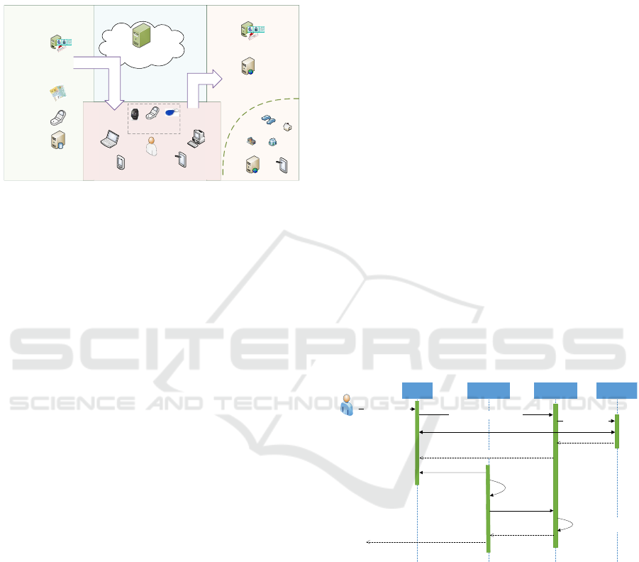
Figure 2 shows the concept of cross-domain eID that
mainly focus on qualified eID in a privacy preserving
and user-centric model. The entities or stakeholders,
which are involved into the eID processing, are par-
tially similar to the stakeholders involved in a classic
WEBIST 2018 - 14th International Conference on Web Information Systems and Technologies
116
identity management system (Bertino and Takahashi,
2010), however the interactions between the stakehol-
ders and the assignments regarding trust relationships
are different. The following itemization gives a short
description of the stakeholders illustrated in Figure 2.
Base-ID register
Qualified eID by
national
governments
Cross-Device
Domain of
eID Sources
Domain of
eID Consumer
eID Processing &
Management
Citizen with
set of devices
Server Component
for Binding
Server Component
for Binding
eIDAS
Interoperability
Framework
National Web-
based Service
Provider
eIDAS Web-based
Service Provider
eID Transfer
eID Use
Personalized
Smart Devices
Figure 2: High-level idea of Cross-Domain eID.
• eID Source: The stakeholders on the left side re-
present a generic set of eID sources that provide
an electronic identity for an entity in a specific
context. In case of qualified eID, the eID source
can be a registration authority (RA), like a natio-
nal register that acts as a trusted third part for eID
attributes and issues qualified eID attributes to the
entity or other stakeholders.
• eID Consumer: The area on the right side repre-
sents an application, service, or device that de-
pends on the identification information. Conse-
quently, the eID consumer has to be in confidence
into the eID information that was provided by an
entity in a user-centric approach. In the concept of
cross-domain eID, such eID consumer can be lo-
cated in different domains and therefore the eID
consumer needs eID information for a specific
context. For example, there can be a legal require-
ment that an eID consumer services need different
identifiers of an entity concerning the domain of
the eID consumer for privacy reasons.
• Entity: An entity or user wants to access a pro-
tected resource of an eID consumer, like service
provider. Therefore, the eID consumer consumes
the eID information selective revealed by the en-
tity to grant or deny access. The eID information,
which was issued by an eID source, is stored on a
personalized smart device in this model.
• Personalized Smart Devices: The personal smart
device that is illustrated in the bottom area is a
subtotal set of devices used by an entity to inte-
ract with eID consumer services by using iden-
tification information issued from an eID source.
In our model, these set of devices are modeled as
semi-trusted. There is a basic trust relationship
according to the security features and there im-
plementation of the smart or mobile device, like
Sandboxing or hardware-based cryptographic ele-
ments. However, there is less confidence due to
high-secure authentication by using these featu-
res on the same level as expressed for example by
smart cards.
3.2 Agile Mobile Authentication for
Smart and Mobile Devices
In respect to the high-level model illustrated in Fi-
gure 2, the proposed process for agile mobile authen-
tication consists of two sub-processes. The first sub-
process is the binding process that transfers and binds
eID information to a smart or mobile device by using
cryptographic operations. The second sub-process is
the eID usage process. During the eID usage process,
an entity uses a smart or mobile device, which is alre-
ady bound to an eID, for identification and authentica-
tion on an eID consumer service in a secure manner.
Figure 3 illustrates the generic binding process of
the agile mobile authentication algorithm. This pro-
cess cryptographically binds an eID that is derived
from an existing entity eID to a smart or mobile de-
vice. The process shown in Figure 3 consists of the
following steps.
Browser
App on
Mobile Device
Identity
Provider
Citizen
Start device
personalization (1)
Start device persoalization (1)
Server
Component
Redirect to IDP (2)
Citizen
identification and authentication
by using eID source (3)
Redirect to
Server Component (4)
Return binding info (5)
Get binding info
via second channel (6)
Generate Keys,
CSR,
Security config (7)
Send CSR and
binding info (8)
Validate CSR and infos
Sign CSR (9)
Return eID token and
X509 certificate (10)
Return process
result to citizen (10)
Figure 3: Generic process to create a cryptographic binding
for device personalization.
1. An entity wants to personalize its smart or mobile
device by using an existing eID. For this purpose,
the entity requests the Server Component that pro-
vides a binding service to personalize devices.
2. The Server Component redirects the entity to an
Identity Provider (IDP) for initial identification
and authentication. This identification and au-
thentication use an existing eID that is provided
by an eID source.
3. The entity execute the identification and authenti-
cation process by using its existing eID. This step
Agile Smart-device based Multi-factor Authentication for Modern Identity Management Systems
117
satisfies the first requirement to support of any eID
source.
4. If the initial identification and authentication is fi-
nished, the IDP sends the existing eID informa-
tion to the Server Component. After this step, the
eID derivation process is almost finished.
5. The Server Component starts the cryptographic
binding process. Therefore, the Server Compo-
nent provides generic binding info that contains
all information that is required to initialize the
binding part of the agile mobile authentication
process. This binding info is provided to the entity
and the smart or mobile device by using a second
channel that is not fixed to a specific technical so-
lution in general.
6. The entity uses a binding application on its smart
or mobile device to receive the initial binding info
over the second channel.
7. If the application receives the initial binding info
than the cryptographic part of the binding process
starts. At first, the application generates a publi-
c/private key pair by using security features pro-
vided by the smart or mobile device. After this,
the application build a certificate-signing request
(CSR) (Turner, 2010) by using the pubic key ge-
nerated before. At last, additional security mea-
sures can be set by the entity to restrict the use
of the private key on the smart or mobile device.
This restriction can be a PIN/password in the sim-
plest case, but also some biometric factors like fin-
gerprint, if it is supported by the smart or mobile
device.
8. In the next step, the application connects to the
Server Component and sends the CSR and the bin-
ding info.
9. The Server Component validates the CSR and the
binding info. If both are valid, then the Server
Component signs the CSR to generate an X509
certificate. The X509 certificate is attached to
the eID information, which was received from the
IDP in step four. The Server Component also
signs the extended eID information. After this,
the eID derivation process is completed.
10. In the last step of the binding process, the deri-
ved eID information is sent to the smart or mobile
device and can be stored by the application. The
result of the binding process is shown to the entity.
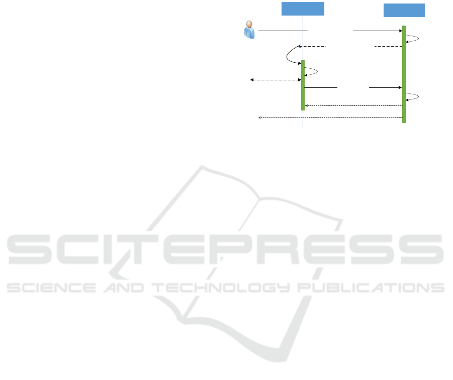
If the binding process was successfully finished
than the entity can use the smart or mobile device for
authentication. Figure 4 illustrates the generic usage
process of the agile mobile authentication algorithm.
This generic process flow shows the usage of a deri-
ved eID that is cryptographically bound to a smart or
mobile device for authentication on a Service Provi-
der. A detailed description of this process is given in
the following.
App on
Mobile Device
Service
Provider (SP)
wants access to SP (1)
Request authentication
Return initial infos via
arbitary channel (3)
Citizen
Need
authentication (2)
Receive initial infos
Generate cryptographic proof (4)
Validate proof
use eID token (6)
Citizen interaction for
proof generation
Return result
message (7)
Send proof and
eID token (5)
SP grant or
deny access (7)
Figure 4: Generic process to use a personalized device for
authentication.
1. An entity wants access to a Service Provider. This
Service Provider is not fixed to a specific type, as
a Web-based application as an example, but could
be any service that requires identification and se-
cure authentication.
2. The Service Provider validates the access request
and request authentication from the entity if it is
needed.
3. To start the proposed agile mobile authentication
process, the Service Provider provides all infor-
mation that is necessary to initialize the algorithm
over an arbitrary channel. This arbitrary channel
is not fixed to a specific technology to satisfy the
requirement to support almost all eID consumer
services.
4. The entity can use its smart or mobile device to
receive the information from the Service Provi-
der. The application generates a cryptographic
proof, by using the private key that was generated
in the binding phase. If the entity has restricted
the access to the private key in the binding phase,
then also additional entity related information is
necessary to complete this cryptographic proof.
5. The application sends the cryptographic proof and
the derived eID information to the Service Provi-
der.
6. The Service Provider can validate the derived eID
information and the proof by using the X509 cer-
tificate that is attached to the derived eID informa-
tion. If the validation is successful than the agile
mobile authentication process is finished and the
derived eID information can be used to identify
the entity.
WEBIST 2018 - 14th International Conference on Web Information Systems and Technologies
118

7. The Service Provider returns the result of the vali-
dation to the application, and after this, the entity
can access the restricted area on the Service Pro-
vider.
3.3 Multi-factor Combination on
Semi-trusted Smart and Mobile
Devices
In this subsection, we illustrate our proposed model
which cryptographically combine at least two authen-
ticators that implement different authentication fac-
tors on a semi-trusted smart or mobile device to incre-
ase the reliability into the authentication process des-
cribe in Section 3.2. In more detail, the proposed mo-
del enhances the management of cryptographic keys
and increases the trust into cryptographic keys that are
created during the cryptographic binding process (see
Figure 3, Step 7) or are used during the authentication
process (see Figure 4, Step 4). Consequently, our ad-
vanced model for multi-factor combination on client
side perfectly fits into the existing cross-domain eID
approach, because these improvements do not influ-
ence other stakeholders besides the entity and the per-
sonalized smart device.
From a cryptographic point of view, threshold
cryptography is used to cryptographically combine
different multiple authentication factors that are im-
plemented as authenticators on different smart or mo-
bile devices. While threshold cryptography itself is
no new cryptographic scheme, and a large body of
research was done around the problem in most gene-
ral form (Boyd, 1986; Croft and Harris, 1989; Fiat
and Shamir, 1987; Gennaro et al., 2001; MacKen-
zie and Reiter, 2004; Schnorr, 1990; Lindell, 2017),
the interest on threshold cryptography has been rene-
wed for the purpose of key protection or distributed
signatures schemes on semi-trusted devices such as
mobile phones or any other smart device. For exam-
ple such key protection approaches by using threshold
cryptography can be used in bitcoin to protect the pri-
vate signing key. However, our proposed model uses
threshold cryptography to distribute the signature ge-
neration capabilities to different authenticators, which
means that more than on cryptographic key is needed
to generate a valid signature.
Threshold cryptography schemes for distributed
signature generation exists for a wide variety of
digital-signature schemes like RSA signing, digital
signature schemes (DSA) based on RSA or ellip-
tic curves (ECDSA), or other signature schemes like
Schnorr signatures (Schnorr, 1990). While it is more
complex to build a distributed signature scheme on
ECDSA signatures as it is more difficult to find a
scheme to compute k and k
−1
without knowing the
private key k, it is much easier to define a distributed
signature for other signature schemes. Schnorr signa-
tures based on elliptic curves are one well example for
such a signature scheme that facilitate distributed sig-
nature generation without complex and time expen-
sive cryptographic operations. Consequently, the el-
liptic curve version of Schnorr signature schemes is
used to integrate distributed signature schemes in our
proposed model of cross-domain eID, as the signature
generation can be easily integrated into lightweight
smart or mobile devices.
According to the concept of cross-domain eID,
our proposed model for multi-factor combination on
semi-trusted mobile or smart devices can be split into
three phases. The first phase is the distributed key ge-
neration, which can be integrated into Step 7 of Figure
3, that generates a virtual asymmetric public/private
key-pair key(PK
binding
,sk
binding
) used for the crypto-
graphic binding described in Step 7. We called this
key pair virtual, because the private key k
binding
does
not exist on one single device, as it is generated dy-
namically from more than one device specific private
keys sk
device
i
, i ∈ (1,...,n) where n is the number of
devices. In more detail, this generation of the public
part of the virtual binding key PK
binding
can be formal
described as PK
binding
= (
∑
n
i=1
sk
device
i
) · G, where G
is the generator of the group. Figure 5 illustrates a
virtual binding-key generation by using two smart de-
vices.
Mobile Device
Second
Authenticator
DSS key pair
sk
Device_1
… Mobile device signing key
PK
Device_1
… Mobile device verification key
(3)
c
Device_2
(7)
c
Device_2
… Hash value for proof of possession
(6)
π
Device_2
... Create a proof of possession
(8)
Generate virtual public key
check proof π
Device_2
Combining PK
Device_2
and PK
Device_2
to PK
Binding
(10)
π
Device_2
(9)
Initialize the distributed key generation process (2)
(1)
want to create a virtual asymmetric
public/private key-pair
DSS key pair
sk
Device_2
… Second Authenticator signing
key
PK
Device_2
… Second Authenticator
verification key
(3)
DSS key pair
r
Device_2
… random number for
proof
A
Device_2
… EC point for r
Device_2
(4)
(PK
Device_2
, A
Device_2
) (5)
Figure 5: Generation of a virtual public/private key-pair by
using two devices.
In the following, we describe this key generation
process in a generic form for more than two devices.
1. The smart or mobile device that should be perso-
nalized by using an already existing eID and the
Agile Smart-device based Multi-factor Authentication for Modern Identity Management Systems
119

authentication should be done by the virtual bin-
ding key key(PK
binding
,sk
binding
)
2. The personalization device sends a request to
every authenticator to start the key generation pro-
cess.
3. Every smart or mobile device that should be used
as an authenticator generates its own asymmetric
private key-pair key(PK
device
i
,sk
device
i
) . The el-
liptic curve point that represents the public key
PK
device
i
is generates as PK
device
i
= sk
device
i
· G,
where G ∈ E/F is the generator. This device
specific asymmetric key-pair can be located in
a hardware-based cryptographic element that is
available on the authenticator.
4. Every authenticator generates a second random
number r
i
∈ F
q
and a corresponding elliptic curve
point A
i
= r
i
· G, where G ∈ E/F
q
the generator
is. The point A is required for the authenticator to
knows the private key sk
device
i
.
5. The authenticator sends the set (PK
device
i
,A
i
) to
the smart or mobile device that should be perso-
nalized.
6. The smart device calculates the hash value c
i
by
using a cryptographic hash function H from input
data c
i
= H(G,PK
device
i
,A
i
).
7. The smart device sends the hash value c
i
to the
authenticator i to get a proof of possession of the
private key sk
device
i
.
8. By using c
i
, every authenticator calculates a proof
π
i
= r
i
+c
i
·sk
device
i
mod q, where q is modulo of
the field F
q
.
9. Every authenticator send its prove π
i
back to the
smart or mobile device that should be personali-
zed.
10. The personalization device checks every proof
π
P
i
. If it is valid, the personalization device adds
the authenticator public key PK
device
i
to PK
binding
.
This simple elliptic curve addition operation can
be done because: PK
binding
= (
∑
n
i=1
sk
device
i
) ·
G =
∑
n
i=1
(sk
device
i
· G) =
∑
n
i=1
PK
device
i
If all pu-
blic keys are added the virtual public binding key
PK
device
i
can be used for the binding process.
The second phase is the distributed signature
generation, which can be integrated into Step 4
of Figure 4 that uses the virtual binding key
key(PK
binding
,sk
binding
) to sign a challenge which is
equivalent to a cryptographic proof. Additionally, this
second phase is also required in Step 7 in Figure 3 to
sign the CSR in the binding process. Figure 6 illus-
trates this distributed signature generation process by
using two devices.
Mobile Device
Second
Authenticator
Initialize the distributed signing process (2)
(R
Device_2
, A
Device_2
) (4)
(1)
want to create a cryptographic proof by using
a virtual asymmetric public/private key-pair
Generate random numbers and EC
points
{k
Device_2
, R
Device_2
}
{r
Device_2
, A
Device_2
}
(3)
c
Device_2
(6)
c
Device_2
… Hash value for proof of possession
(5)
π
Device_2
(8)
π
Device_2
... Create a proof of
possession
(7)
Generate ephemeral key R
check proof π
Device_2
Combining R
Device_2
and R
Device_2
to R
(9)
Generate random numbers and EC points
{k
Device_1
, R
Device_1
}
(3)
R
(10)
Generate signature
e … Hash value
(s
Device_2
, e) …. Signature
(11)
Generate signature
e … Hash value
(s
Device_1
, e) …. Signature
(11)
(s
Device_2
, e) (12)
Generate final signature
Combining (s
Device_1
, e) and (s
Device_2
, e) to (s, e)
(13)
Figure 6: Distributed signature creation by using two devi-
ces.
In a generic form and with more detail, a distri-
buted signature generation consists of the following
steps:
1. The personalized smart or mobile device is re-
quested by an eID consumer server to generate a
cryptographic proof, by using the virtual private
key sk
binding
) that was generated in the first phase.
This cryptographic proof can be a digital signa-
ture which uses an elliptic curve Schnorr signa-
ture scheme on an input message m that was sent
by the eID consumer service.
2. The personalized smart or mobile device genera-
tes a distributed signature initialization requests.
3. Every authenticator receives the signature initiali-
zation request and generates new random k
i
∈ F
q
where F
q
is the field over the elliptic curve E. By
using k
i
, the authenticator can calculates a new
random point R
i
= k
i
· G, where R
i
∈ E/F and G
is the generator.
In addition, every authenticator generates a se-
cond random number r
i
∈ F
q
and a corresponding
elliptic curve point A
i
= r
i
· G, where G ∈ E/F
q
is
the generator. The point A is one step of the proof
that the authenticator knows the random value k
i
.
4. Every authenticator send the set (R
i
,A
i
) to the per-
sonalized smart device.
5. The smart device calculates the hash value c
i
by
using a cryptographic hash function H from input
data c
i
= H(G,R
i
,A
i
).
6. The smart device sends the hash value c
i
to the
authenticator i to get a proof of possession of the
WEBIST 2018 - 14th International Conference on Web Information Systems and Technologies
120

private key k
i
.
7. By using c
i
, every authenticator calculates a proof
π
i
= r
i
+ c
i
· k
i
mod q, where q is modulo of the
field F
q
.
8. Every authenticator sends its prove π
i
back to the
smart or mobile device that should be personali-
zed.
9. The personalized smart device checks every proof
π
i
. If it is valid, the personalization device adds
the random points R
i
to R. This is a simple elliptic
curve addition operation as: R = (
∑
n
i=1
k
i
) · G =
∑
n
i=1
(k
i
· G) =
∑
n
i=1
R
i
.
10. The personalized smart device generates a distri-
buted signature creation request that contains the
message m and the sum of the randomly generates
points R.
11. Next, every authenticator generates a crypto-
graphic hash e from input message m and the
random point R by calculating e = H(m||R),
where H is the cryptographic hash function. At
last, the authenticator computes the signature va-
lue s by calculating s = k − sk
device
i
· e mod q,
where k is the random number, e hash value, and
sk
device
i
is the private key of a specific authentica-
tor.
12. Every authenticator sends the signature σ
i
(s
i
,e)
back to the personalized device.
13. If all signatures σ
i
(s
i
,e) are received, the persona-
lized smart device can aggregate the single signa-
ture σ
i
(s
i
,e) , by simple adding the single signa-
ture values s
i
to s =
∑
n
i=1
s
i
mod q. This sample
add operation is possible, because s
i
was created
only by linear operations. After this, the process
of signature creation is completed and the signa-
ture σ
m
(s,e) for message m can be used as a proof
of possession for the virtual secret key sk
binding
).
The third phase is the signature verification phase
in which an eID consumer service can verify the cryp-
tographic signature that is used to authenticate the en-
tity. This signature verification step is part of Step 6
in Figure 4. From an eID consumer point of view,
this verification phase is equal to the verification of
an elliptic curve Schnorr signature by using the vir-
tual public key PK
binding
from the personalized smart
or mobile device. More details on cryptographic buil-
ding blocks for the Schnorr signature scheme and ot-
her basic cryptographic primitives that we used in our
proposed model for multi-factor combination on mo-
bile or smart devices are described in the Appendix
6l.
We have evaluated the practical applicability of
the proposed model for multi-factor combination on
mobile or smart devices by realizing two applications
for smart devices that implement our proposed model.
4 IMPLEMENTATION OF
MULTI-FACTOR
COMBINATION ON
CLIENT-SIDE
We used our proposed model of client-side multi-
factor combination for entity authentication to imple-
ment and demonstrate the practical applicability in
practice. This implemented solution consists of two
applications for smart devices. The first application is
a mobile-phone application that stores and manages
the eID information in a secure way and implements
the first authenticator regarding our proposed model.
This mobile phone application can be used as perso-
nalized smart device regarding the concept of cross-
domain eID. We implement a mobile-phone applica-
tions for the Android Operation System (Android OS)
7
that provides all functionality for binding and usage
of eID information, by implementing our multi-factor
combination approach.
The second one is a smart-watch application that
implements a second authenticator for our proposed
model. For the second authenticator different smart
watches were used, for example, a SmartWatch 3
from Sony
8
, but every device runs on the Android
Operation System. We implement an application for
smart watches that perform all cryptographic operati-
ons, which are required in our model. Also, this appli-
cation has a simple user interface to protect the secret
key by using a PIN approach.
From a cryptographic point of view, we use the
elliptic curve P-256 from (Kerry et al., 2013) to im-
plement our proposed model of a multi-factor com-
bination. The basic implementation of the Schnorr
signature scheme, which is used in our model, was
done according to the recommendations from BSI TR-
03111 (BSI, 2018). However, we modify the signa-
ture creation described in BSI TR-03111 according to
Section 3.3 to facilitate distributed signature creation.
To implement the proof of possession, which is used
in Section 3.3, we use the Schnorr NIZK Proof over
Elliptic Curve from RFC 8235 (Hao, 2017). By using
these cryptographic schemes, we could illustrate the
practical applicability of our proposed model by de-
veloping two authenticators that are implemented as
smart applications.
7
https://www.android.com/
8
https://www.sonymobile.com/global-
en/products/smart-products/smartwatch-3-swr50
Agile Smart-device based Multi-factor Authentication for Modern Identity Management Systems
121

5 EVALUATION
The successful implementation of two authenticator
prototypes for multi-factor combination on client-side
has shown the feasibility of the proposed model. In
order to evaluate the capabilities of our solution in a
real-world scenario, we have deployed and tested the
implementation with test deployments of real eGo-
vernment infrastructure components. We deployed
the server component of the already existing cross-
domain eID infrastructure that was used during some
evaluation phases in 2016 and 2017 (Lenz and Al-
ber, 2017). By using this deployment, Austrian ci-
tizen can use there national eID cards to personalized
there mobile phones. To evaluate the use of propo-
sed model for multi-factor combination, we have de-
ployed some demo service-provider that can be used
by entities to test the advanced authentication process,
which is illustrated in this paper. First internal tests
shows practical applicability of our proposed model
and illustrates the smooth integration into the existing
cross-domain eID infrastructure. Currently, we are in
the starting phase of a pilot to evaluate the proposed
model in a bigger group of entities to get more de-
tailed information on usability aspects regarding our
model.
6 CONCLUSION
In this paper, we have presented an agile smart-device
based multi-factor authentication process to facilitate
identification and high-secure authentication on any
service provider by using smart or mobile devices.
Due to the increasing number of smart devices that
process sensitive data, identification and authentica-
tion on and from smart or mobile devices become
indispensable. While eID processes are widely ex-
amined for Web-based applications and PCs, the si-
tuation is more demanding on smart or mobile devi-
ces. A first already published approach brings agile
authentication to be a smart or mobile device. Ho-
wever, this approach lacks in respect to high secure
authentication, as authentication was done from a sin-
gle semi-trusted device. To antagonize this lack of
reliability into entity authentication, we propose an
advanced multi-factor based approach for entity au-
thentication that cryptographically combines at least
two key-pairs on entity side. By using this, we can
significantly increase the reliability of the authenti-
cation process. We have demonstrated the practical
applicability of our proposed multi-factor authentica-
tion process by implementing all components of the
proposed model. A first evaluation pilot is starting to
evaluate the usability of our proposed model.
REFERENCES
(2018). Bsi tr-03111: Elliptic curve cryptography, version
2.1.
27, I. J. S. (2011). Information technology Security techni-
ques A framework for identity management Part 1:
Terminology and concepts. Technical Report 24760-
1, ISO/IEC.
Bertino, E. and Takahashi, K. (2010). Identity Management:
Concepts, Technologies, and Systems. Artech House,
Inc., Norwood, MA, USA.
Boneh, D. (2005). Schnorr Digital Signature Scheme, pages
541–542. Springer US, Boston, MA.
Boyd, C. (1986). Digital multisignatures. In In Crypto-
graphy and Coding, pages 241 – 246.
Burr, W. E., Dodson, D. F., Newton, E. M., Perlner, R. A.,
Polk, W. T., Gupta, S., and Nabbus, E. A. (2013).
Electronic authentication guideline. Technical Report
800-63-2, National Institute of Standards and Techno-
logy (NIST).
Chatzigiannakis, I., Pyrgelis, A., Spirakis, P., and Stama-
tiou, Y. (2011). Elliptic curve based zero knowledge
proofs and their applicability on resource constrained
devices.
Corella, F. and Lewison, K. (2012). Techniques for imple-
menting derived credentials. Technical report, Pomcor
Research in Mobile and Web Technology.
Corella, F. and Lewison, K. (2014). An example of a deri-
ved credentials architecture. Technical report, Pomcor
Research in Mobile and Web Technology.
Croft, R. A. and Harris, S. P. (1989). Public-key cryp-
tography and reusable shared secrets. In In Crypto-
graphy and Coding, pages 189 – 201.
Entrust, e. a. (2014). Mobile derived piv/cac credential - a
complete solution for nist 800-157. Technical report,
Entrust Datacard.
European Union (2015). Commission implementing regula-
tion (eu) 2015/1501 of 8 september 2015 on the inter-
operability framework pursuant to article 12(8) of re-
gulation (eu) no 910/2014 of the european parliament
and of the council on electronic identification and trust
services for electronic transactions in the internal mar-
ket. European Union.
Ferraiolo, H., Cooper, D., Francomacaro, S., Regenscheid,
A., Mohler, J., Gupta, S., and Burr, W. (2014a). Gui-
delines for derived personal identity verification (piv)
credentials. Technical Report 800-157, National Insti-
tute of Standards and Technology (NIST).
Ferraiolo, H., Regenscheid, A., Cooper, D., and Franco-
macaro, S. (2014b). Mobile, piv, and authentication.
Technical Report Draft NISTIR 7981, National Insti-
tute of Standards and Technology (NIST).
Fiat, A. and Shamir, A. (1987). How to prove yourself:
Practical solutions to identification and signature pro-
blems. In Odlyzko, A. M., editor, Advances in Cryp-
tology — CRYPTO’ 86, pages 186–194, Berlin, Hei-
delberg. Springer Berlin Heidelberg.
WEBIST 2018 - 14th International Conference on Web Information Systems and Technologies
122

Flor
ˆ
encio, D., Herley, C., and Van Oorschot, P. C. (2014).
An administrator’s guide to internet password rese-
arch. In Proceedings of the 28th USENIX Confe-
rence on Large Installation System Administration,
LISA’14, pages 35–52, Berkeley, CA, USA. USENIX
Association.
Gennaro, R., Jarecki, S., Krawczyk, H., and Rabin, T.
(2001). Robust threshold dss signatures. Information
and Computation, 164(1):54 – 84.
Grassi, Paul A. Garcia, M. E. and Feton, J. L. (2017).
Digital identity guidelines. Technical Report 800-
63-3, National Institute of Standards and Technology
(NIST).
Grassi, P. A., Fenton, J. L., Newton, E. M., Perlner, R. A.,
Regenscheid, A. R., Burr, W. E., and Picher, J. P.
(2017). Digital identity guidelines - authentication and
lifecycle management. Technical Report 800-63b, Na-
tional Institute of Standards and Technology (NIST).
Hao, F. (2017). Schnorr Non-interactive Zero-Knowledge
Proof. RFC 8235.
Haupert, V. and Mller, T. (2016). (in)security of app-
based tan methods in online banking. University of
Erlangen-Nuremberg, Germany.
Hayikader, S., Hanis binti Abd Hadi, F. N., and Ibrahim, J.
(2016). Issues and security measures of mobile ban-
king apps. International Journal of Scientific and Re-
search Publications, 6.
ISO/IEC (2013). ISO/IEC 29115. Information technology –
Security techniques – Entity authentication assurance
framework. International standard, International Or-
ganization for Standardization.
ISO/IEC (2016). ISO/IEC COMMITTEE DRAFT 29003.
Information technology – Security techniques Iden-
tity proofing. Technical report, International Organi-
zation for Standardization.
Jøsang, A., Zomai, M. A., and Suriadi, S. (2007). Usabi-
lity and privacy in identity management architectures.
In Proceedings of the Fifth Australasian Symposium
on ACSW Frontiers - Volume 68, ACSW ’07, pages
143–152, Darlinghurst, Australia, Australia. Austra-
lian Computer Society, Inc.
Kerry, C. F., Secretary, A., and Director, C. R. (2013). Fips
pub 186-4 federal information processing standards
publication digital signature standard (dss).
Kim, J.-J. and Hong, S.-P. (2011). A method of risk asses-
sment for multi-factor authentication. JIPS, 7:187–
198.
Lenz, T. and Alber, L. (2017). Towards cross-domain eid
by using agile mobile authentication. In 2017 IEEE
Trustcom/BigDataSE/ICESS, pages 570–577.
Lenz, T. and Zwattendorfer, B. (2015). A modular and flex-
ible identity management architecture for national eid
solutions. In 11th International Conference on Web
Information Systems and Technologies, pages 321 –
331.
Lindell, Y. (2017). Fast secure two-party ecdsa signing. In
Katz, J. and Shacham, H., editors, Advances in Cryp-
tology – CRYPTO 2017, pages 613–644, Cham. Sprin-
ger International Publishing.
MacKenzie, P. and Reiter, M. K. (2004). Two-party ge-
neration of dsa signatures. International Journal of
Information Security, 2(3):218–239.
Mohammed, M. M. and Elsadig, M. (2013). A multi-
layer of multi factors authentication model for online
banking services. In 2013 International Conference
on Computing, Electrical and Electronic Engineering
(ICCEEE), pages 220–224.
Sarikhani, R. (2008). Language and american social iden-
tity.
Schnorr, C. P. (1990). Efficient identification and signatures
for smart cards. In Brassard, G., editor, Advances in
Cryptology — CRYPTO’ 89 Proceedings, pages 239–
252, New York, NY. Springer New York.
Taneski, V., Heriko, M., and Brumen, B. (2014). Password
security - No change in 35 years? In 2014 37th In-
ternational Convention on Information and Communi-
cation Technology, Electronics and Microelectronics
(MIPRO), pages 1360–1365.
Turner, S. (2010). The application/pkcs10 Media Type.
RFC 5967.
Zwattendorfer, B. (2014). Towards a privacy-preserving fe-
derated identity as a service-model.
APPENDIX
Digital Signatures
In a nutshell, a digital signature scheme uses a mes-
sage M and an asymmetric key-pair key(sk
sig
, pk
sig
)
to produce a digital signature σ by using M and the
private key sk
sig
from asymmetric key-pair. A verifier
can use the signature σ, the message M and the public
key pk
sig
from asymmetric key-pair to check the in-
tegrity (σ has been issued for M) and the authenticity
(σ was produced by the holder of the corresponding
signing key sk
sig
) of the signature.
In a more formal way, a digital signature scheme
(DSS) is a set (K, S,V ) of poly-times algorithms. The
first algorithm DSS
K
takes a security parameter k to
generate an asymmetric key-pair DSS
K
(sk
sig
, pk
sig
)
where the private key is sk
sig
and the public key is
pk
sig
. The second algorithm DSS
S
is the signing
algorithm. This signing algorithm uses a message
M ∈ {0,1}
∗
and a private key sk
sig
as input data and
outputs a signature σ = DSS
S
(sk
sig
,m). The third al-
gorithm DSS
V
is the verification algorithm. This ve-
rification algorithm uses the message M ∈ {0,1}
∗
,
a public key pk
sig
, and a signature σ as input data
and outputs a single bit b = RS
V
(σ,M, pk
sig
), b ∈
{true, f alse} that indicates if the signature σ is va-
lid for M or not. Also, in a practical implementation
the message M is not directly used as input data in
DSS
S
and DSS
V
but rather H(M), where H is a cryp-
tographic hash function.
Agile Smart-device based Multi-factor Authentication for Modern Identity Management Systems
123

Ellipic-curve based Schnorr Signatures
Briefly, Schnorr signatures are a digital signature
scheme that based on the Schnorr algorithm for iden-
tification and signature creation. The Schnorr appro-
ach was proposed by Schnorr in 1990 as a lightweight
algorithm for identification and signature creation on
smart cards. (Schnorr, 1990). The signing algorithm
uses an asymmetric key-pair key(sk
sig
, pk
sig
) to pro-
duce a digital signature σ = (R,s) by using an input
message M and the private key sk
sig
from asymmetric
key-pair. A verifier can use the signature σ = (R, s),
the public key pk
sig
, and the message M
In a more formal way, a elliptic curve base
Schnorr digital signature scheme (ECSDSA) is a
set (K,S,V ) of poly-times algorithms. The first
algorithm ECSDSA
K
chooses an elliptic curve E
over a finite field F
q
. Next, the algorithm rand-
omly selects a elliptic curve point G ∈ E(F
q
), where
G is the generator in the following steps. In the
last step, the algorithm ECSDSA
K
takes a secu-
rity parameter k to generate an asymmetric key-pair
ECSDSA(sk
ECSDSA
, pk
ECSDSA
) where the private key
is sk
ECSDSA
∈ [1,r], where r is the order of P and the
public key is PK
ECSDSA
= sk
ECSDSA
· P. The full pu-
blic key pk
set
is the set (PK
ECSDSA
,P) if the genera-
tor P was randomly chooses. The second algorithm
ECSDSA
S
is the signature algorithm. The signature
algorithm generates random number k ∈ [1,r], where
r is the order of P. After this, a new elliptic curve
point R is calculated, where R = k · P, and P is the
generator select in ECSDSA
K
. In the next step, cryp-
tographic hash value e is calculated by using a crypto-
graphic hash function H() and the message M and the
point P as input data. These means that e = H(M||R),
where H : 0 : 1
∗
→ [1,r] and r is the order of the ge-
nerator P, and || is a concatenation of M and R. At
last, the signature σ
M
= (R, s) is generated, where
R is the point generated before and s is calculated
from s = k + sk
ECSDSA
·e mod r. The third algorithm
ECSDSA
V
is the verification algorithm. This verifi-
cation algorithm used the public key PK
ECSDSA
, the
generator R, the message M and the signature σ
M
=
(R,s) and outputs a single bit b
M
∈ {true, f alse} that
indicates if the signature σ
M
is valid for M, otherwise
not. At first, the algorithm ECSDSA
V
calculates the
hash value e using a cryptographic hash function H()
and the message M and the point P, which is part of
the signature σ
M
. The single bit b
M
∈ {true, f alse}
is the proof, if R + e · PK
ECSDSA
= s · P, where R and
s are part of the signature σ
M
, and P is the genera-
tor.(Schnorr, 1990; Boneh, 2005; Lindell, 2017)
Proof of Knowledge of the Discrete Log
of an Elliptic-curve Point
Briefly, a proof of knowledge of the discrete log of
an elliptic-curve point means the follows. For a gi-
ven elliptic curve E over a finite field F
q
, a generator
G ∈ E/F
q
, and an elliptic curve point P ∈ E/F
q
, a pro-
ver wants to prove that he knows a value x such that
B = x · G, without revealing x. In respect to the el-
liptic curve discrete logarithm problem (ECDLP) it is
very hard for an attacker to calculate a valid proof wit-
hout knowing x. There exists different interactive and
non-interactive zero-knowledge schemes that provide
functionality to proof the possession of x (Chatzigi-
annakis et al., 2011; Hao, 2017). In this work, use
a non-interactive zero-knowledge proof based on the
Schnorr protocol; because it is lightweight, that me-
ans that it can be well integrated into smart or mobile
devices. Therefore, we will give more details on this
specific zero-knowledge proof.
More formally, the non-interactive zero-
knowledge proof based on the Schnorr protocol
consists of the following steps. In the initialize phase,
a prover and a verifier agree on an elliptic curve E
over a finite field F
q
and a generator G ∈ E/F
q
. The
prover and the verifier knows an elliptic curve point
B ∈ E/F
q
and the prover claims that he knows a value
x such that B = x · G. This fact should be proven to
the verifier without revealing x.
1. The prover generates a random number r ∈ F
q
and
computes the corresponding elliptic curve point
A = r · G.
2. The prover sends the elliptic curve point A to the
verifier
3. The verifier computes a value c by using a cryp-
tographic hash function H(), where H : 0 : 1
∗
→
[1,r] and r is the order of the generator G. The
value c is generated by c = H(G, B,A), where G,
B and A are the hash input data.
4. The verifier sends the value c to the prover
5. The prover computes the proof m as m = r + c ∗ x
mod q
6. The prover sends the proof m to the verifier
7. The verifier can check that P = m·G − c ·B = (r +
c ∗ x) · G −c · B = r · G + c · x · G −c · x · G = r · G =
A. If m · G − c · B = A than the prover knows x,
otherwise the proof fails.
From a security point of view, a dishonest prover
has a tiny chance for cheating as he would have to
fix the value of P = m · G − c · B before receiving the
hash value c from the verifier. However, under the
assumption that the cryptographic hash function H()
is secure, a prover that does not know x cannot cheat
in respect to the discrete logarithm of B.
WEBIST 2018 - 14th International Conference on Web Information Systems and Technologies
124
