
Nitrogen Foam Profile Control Improves Steam Huff and Puff
Development Effect
Jicheng Zhang
1
, Qingqing Li
1,*
, Xinyu Chen
1
, Guangfu Lu
1
and Li Liu
2
1
Northeast Petroleum University, School of Petroleum Engineering, Daqing, Heilongjiang;
2
Department of Flow in Porous Media & Fluid Dynamics, Research Institute of Petroleum Exploration & Development,
Langfang, Hebei.
Email: 1525841456@qq.com.
Key words: Steam huff and puff, nitrogen foam, profile control, heavy oil, remaining oil
Abstract. After the XQ-45 block entering the multiple rounds of steam huff and puff, it is affected by faults, reservoir
properties, edge water and other factors. The remaining oil distribution is complex, and steam huff and puff
effect is getting worse. According to the reservoir dynamic data, this block is selected as a test block to
improve the steam huff and puff development effect of nitrogen foam. The 79 wells in this block are divided
into different types of heavy oil wells according to the remaining oil saturation parameters. Aiming at the
high-level intervals in the oil wells with different layers, then take nitrogen foam profile control measures to
adjust the suction profile, and optimize the optimal nitrogen foam injection parameters are: nitrogen foam
injection volume is 0.2pv, foam concentration is 0.5%, gas liquid ratio is 2: 1, cycle steam injection volume
is 100t/m. The results show that the oil production is the largest in the second round of profile control, the
average daily oil production is 3.89t, and the cycle oil-gas ratio reaches 0.32. On this basis, continue to
increase the profile control round, after the profile control 5 rounds, the average daily oil production is
3.18t, the average oil-gas ratio is 0.26, the cycle of cumulative oil production is 1431.23t, and the program
implementation effect is getting better.
1 INTRODUCTION
At home and abroad the application of foam fluid
has nearly 30 years of history in oil field. The
composition form of foam fluid is also evolved from
single ordinary foam flooding to current compound
nitrogen foam flooding (Zhao et al., 2009; Yang,
2014; Huseyin, 2013). After the 80’s, domestic oil
field has made a major breakthrough in the
application of foam fluid technology. The foam is
gradually recognized as main mechanism to improve
recovery ratio of heavy oil after entering multiple
rounds of steam huff and puff (Zhang et al., 2012; Li
et al., 2007; Tian, 2015), it has conducted the
relevant indoor and field study in the field.
Zhang Liehui etc have proposed foam flooding
empirical model. Compared with other models, the
model except adds a surface active agent flowing
equation, the model does not require any additional
large amounts of data. This feature makes this model
widely used in the software customization
(Zhang et
al., 2000; Fan et al., 2009; Rossen and Zhou 1994);
Liao Guangzhi, Chen Guo etc have established a
mathematical model to describe polymer alkali
active agent and foam fluid combination flooding
(Chen et al., 2001; Zhang et al., 2012; Malcolm,
2004). Aimed at the second north block in Shengli
oil field, and launched a pilot test to improve
recovery ratio of injecting nitrogen foam. It is found
that technology of nitrogen foam can effectively
supplement layer capability in this block and
improve swept volume (Zhou et al., 2006; Cao et al.,
2013; Cao et al., 2006). With the effect of weak gel
profile control rapid decline, liaohe oil field has
established laboratory test of nitrogen foam profile
control. According to laboratory findings, confirmed
a series of field nitrogen foam injection scheme. It is
demonstrated that inject nitrogen foam can
effectively plugging tall permeation high capacity
channel of oil layer, enhance swept volume, and
improve effect of water injection (Yang et al., 2004;
Islam et al., 1989). Aimed at the needs of Daqing
Zhang, J., Li, Q., Chen, X., Lu, G. and Liu, L.
Nitrogen Foam Profile Control Improves Steam Huff and Puff Development Effect.
In Proceedings of the International Workshop on Environment and Geoscience (IWEG 2018), pages 223-232
ISBN: 978-989-758-342-1
Copyright © 2018 by SCITEPRESS – Science and Technology Publications, Lda. All rights reserved
223
Sabei oil field development, and launched pilot test
of nitrogen foam flooding in the Beiding well and
xing well. It is confirmed that availability of
nitrogen foam flooding in the field is good, and
foam combination flooding can improve oil
recovery 30% than water flooding (Zhang et al.,
2001; Wang and Zhang, 2007; Islam, 1989).
After XQ-45 block entering the high cycle of
steam huff and puff, distribution of remaining oil is
complex, and the effect of steam huff and puff is
getting worse. Due to the heterogeneity of reservoir
layers, steam overlapping and steam enthalpy occur,
which leads to steam escaping along the high
permeability zone, making the steam sweep
efficiency small, greatly reducing the effective
steam sweep area and affecting the efficiency of
steam huff and puff. Aiming at this issue, in order to
further study the effect of nitrogen foam profile to
improve the development of steam huff and puff, the
block wells are divided into five types of remaining
heavy oil wells, potential of these five remaining oil
wells is analyzed and nitrogen profile study of the
most potential inter-layer differential wells is
conducted. Parameters of optimal nitrogen foam
injection are optimized, and effect of nitrogen foam
profile control inter-layer differential wells
development is confirmed.
2 BLOCK OVERVIEW
2.1 Reservoir Geological Features
XQ-45 block is located in the north east direction of
the Xinzhuang complex fault block in the northern
slope of the Biyang depression. This part of strata is
mainly composed of three different oil groups and
unconformity contact of angle in the third system.
The whole area contains oil-bearing horizon
group Ⅱ. The main oil layers are H3Ⅱ2 oil layer,
H3Ⅱ3 oil layer, H3Ⅱ5 oil layer and H3Ⅱ6 oil
layer, and effective thickness of oil layer is 0.8-10.4
meters. Buried depth of reservoir is 75 ~ 245m, the
average of oil layer assemble thickness is 8.2m, and
the pure gross thickness ratio is 0.5-0.99. Reservoir
lithology mainly consists of linen rudstone, glutenite
and siltstone. Cementing materials are dominated by
earthy material. Type of cementation is generally as
pore cement. Oil reservoir has better physical
properties with average porosity of 30.44% and
mean permeability of 2209.4×10
-3
µm
2
. Relative
density of ground crude oil between 0.9361 cm
3
and
0.9666g/cm
3
, content of gummy asphalt is 6.3%~
33.43%, paraffin content is 2.87%~9.06%, sulfur
content is 0.03%~0.12%, solidifying point is -2℃
~7℃, viscosity of degassed crude oil is 11258~
20876mPa·s, which belongs to particularly heavy oil
reservoir.
2.2 Steam Huff and Puff Development
Process
XQ-45 block has been put into large scale
development since 2005. After five years of steam
huff and puff, by the end of April 2011, a total of 76
oil wells have been put into production, with
cumulative liquid production is 110.23×10
4
t,
combined water content is 85.7% and cumulative
oil-gas ratio is 0.23.
Since June 20, 2011, due to infancy of steam
flooding is not effective and oil-gas ratio is poor.
XQ-45 block implements injection and production
parameters adjustment, nitrogen foam assists steam
flooding and other measures, it is found that steam
flooding production wells gradually effective, daily
oil production and oil-gas ratio increase year by
year. By the end of December 2015, a total of 72 oil
wells have been devoted to development and 58
wells as open wells. The average single well
throughput is 10 cycles, daily fluid production is
523.6t, daily oil production is 32.1t, and water
content is 93.9%. Cumulative oil production is
22.7049×10
4
t, degree of reserve recovery of
producing reserves is 23.3%, cumulative steam
injection volume is 94.6038×10
4
t, and cumulative
oil-gas ratio is 0.24.
2.3 The Main Problems in the
Development Process
With increase of the number of throughput cycles,
development effect of the block gradually
deteriorated. At present, the average steam huff and
puff cycle has reached more than 10 cycles and the
average of degree of reserve recovery is about
18.6%. The average single-well daily production is
only 0.6t and oil-gas ratio is about 0.13. After the
development of high cycle throughput and steam
flooding, following problems mainly restraint the
effect of development and the increase of recovery
ratio: (1) Section plane heterogeneity is strong, and
degree of utilization is disproportionation. (2) After
high cycle of steam huff and puff, pressure is low,
IWEG 2018 - International Workshop on Environment and Geoscience
224
and daily liquid production of single well is low.
Oil-gas ratio is low and the effect of development is
poor. There are many low production wells and
invalid production wells. In the XQ-45 zone, the
average steam cycle has reached 10 cycles, the
formation pressure has dropped to 0.8MPa-1.2 MPa,
and the pressure maintenance level is only about
40%.At present, the average daily production of
single well is 9t, daily oil production is 0.6t , water
content is 93.3%, oil-gas ratio is 0.13, which has
poor development. Among them, there are 10
normal production wells with daily production of
more than 1.0t and 49 low-efficiency wells with
daily production of less than 1.0t. (3) Remaining oil
distribution is complex, and the realization of
tapping potential is difficult. The remaining oil
recognition method is only the logging interpretation
method and the reservoir engineering method, and it
is limited to single well points and small layers. The
remaining oil potential is difficult to recognize and
evaluate, and it restricts the fine adjustment and
potential tapping of the reservoir in the later period.
3 CLASSIFICATION AND
POTENTIAL ANALYSIS OF
REMAINING OIL TYPES IN
HEAVY OIL WELL
3.1 Remaining Oil Classification of
Five Heavy Oil Wells
Combining actual production data of liquid
producing capacity, gas injection volume and water
content of each well, and based on the data of
geologic analysis and well logging interpretation.
According to different parameters such as remaining
oil saturation and degree of reserve recovery, 79
wells in XQ-45 block are measured to establish the
classification criteria.
There is edge water in the small layers of block,
and area of edge water block is unequal. With the
continuous of the process of pressure releasing and
producing, edge water along the high permeability
zone with better physical property advances into the
well. At this time, oil productive capacity rapid
decline, water production rapid increase. As a result,
layers around oil wells are not evenly used, and they
are identified as oil wells affected by edge water.
The block is mainly controlled by faults, and the
radius of oil drainage is significantly affected by
faults. The value of remaining oil saturation nears
the fault is relatively high, and degree of reserve
recovery is relatively low. So that, oil wells in this
block are confirmed fault screened heavy oil wells.
The criteria for dividing inter-layer differential
type of remaining oil is: the value of average
remaining oil saturation difference between H3II2,
H3II3, H3II5 and H3II6 four layers are≥0.12.
The criteria for dividing intra-layer differential
type of remaining oil is: the value of remaining oil
saturation difference in the three small layers of
H3II31, H3II32 and H3II33 are≥0.08.
According to the distribution of the remaining oil
saturation field, except for the types of remaining oil
wells above, which the remaining oil wells are still
rich at the end of the recovery, are divided into the
interwell enrichment remaining oil wells.
On the basis of the results of the five types of
remaining oil, the single well controlled geological
reserves are calculated according to the volumetric
method, and the degree of reserve recovery of the
five type of remaining oil type wells are analyzed.
The average degree of reserve recovery of interwell
enrichment wells is 22.9%, the average degree of
reserve recovery of intra-layer differential remaining
oil wells is 28.1%, the average degree of reserve
recovery of inter-layer differential remaining oil
wells is 24.5%, the average degree of reserve
recovery of edge water affected wells is 21.7%, and
the average degree of reserve recovery of fault
screened oil wells is 8.23%.
3.2 Potential Analysis of Five Type
Remaining Oil Wells
According to the degree of reserve recovery of the
five type remaining oil wells, the remaining oil
potential classification evaluation is performed. The
remaining oil potential evaluation criteria are: the oil
wells with less than 10% degree of reserve recovery
have the high potential of remaining oil, the oil
wells with degree of reserve recovery of 10%-25%
have the medium potential of remaining oil, the oil
wells with more than 25% degree of reserve
recovery have the low potential of remaining oil. It
is concluded that the order of the production of five
types of heavy oil wells is as follows: intra-layer
differential type > inter-layer differential type >
interwell enrichment type > edge water effected
type>fault screened type.
According to the evaluation criteria for
remaining oil potential, the remaining geological
Nitrogen Foam Profile Control Improves Steam Huff and Puff Development Effect
225
reserves of the five remaining oil types are
calculated. The order from high to low is as follows:
inter-layer differential type> edge water effected
type> fault screened type> interwell enrichment
type> intra-layer differential type.
According to the above analysis, the remaining
oil potential of the five heavy oil wells is as follows:
inter-layer differential type> edge water effected
type> fault screened type> interwell enrichment
type> intra-layer differential type. It is can be seen
that the inter-layer differential type remaining oil is
the high potential of the remaining oil in the five
heavy oil wells, so the analysis its causes.
3.3 Analysis the Development of Inter-
Layer Differential Type Remaining
Oil Wells
The formation and distribution of inter-layer
differential type remaining oil are mainly affected
by interlayer barrier, inter-layer heterogeneity and
perforation interval. The virgin formation oil layers
in the same wells generally maintain characteristics
of the native reservoir, and a high remaining oil
distribution in the local zone is formed. The
temperature loss of barrier limits the effective range
of steam flooding, so that more remaining oil is
formed in the upper part of barrier to form a high
remaining oil enrichment zone. The inter-layer
thermal interference makes high permeability layers
communication transform to form steam
communication, so that the relatively low
permeability layer or disconnected layer form high
remaining oil.
4200 well in the block is selected to analysis. For
H3II3 layer, the value of porosity is 32.96%, the
value of permeability is 1660×10
-3
μm
2
, and the
value of remaining oil saturation is 0.41. For H3II5
layer, the value of porosity is 39%, the value of
permeability is 479×10
-3
μm
2
, and the value of
remaining oil saturation is 0.54. For the two layers
mentioned above, the difference value of
permeability is 1181×10
-3
μm
2
, and the difference
value of remaining oil saturation is 0.13. Conflicts
between layers is large, thus inter-layer differential
type of remaining oil is formed.
4 STUDY ON NITROGEN FOAM
PROFILE CONTROL INTER-
LAYER DIFFERENTIAL TYPE
OIL WELLS
According to the inter-layer differential type
remaining oil wells, on the basis of actual
production data such as the potential productivity of
single-layer remaining oil, the effective thickness of
oil layer, the cumulative oil production and the
degree of reserve recovery. The representative 4003
well and 4502 well are selected to optimize design.
Due to the difference heterogeneity of reservoir
layers, steam overlapping and gas channeling occur.
It is results that the steam rushes into the high
permeability zone, makes sweep efficiency of steam
small and greatly reduces the effective area of
steam, thus affects the efficiency of steam huff and
puff. Aiming at the high degree of reserve recovery
of layer in inter-layer differential type oil wells, the
nitrogen foam profile control measures are adopted
to adjust the gas injection profile and mode of two
layers commingled production. The nitrogen foam
profile control parameters and steam injection
parameters are optimized, including nitrogen foam
injection volume, gas fluid ratio (nitrogen: foam
liquor), foam concentration and cycle steam
injection volume. Using the numerical simulation
method and combining with the economic benefit
analysis under the current low oil price, the best
solution is obtained by obtaining the maximum
crude output and the economic limit oil gas ratio
greater than 0.2 as the evaluation standard.
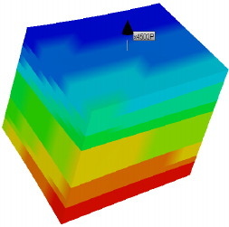
4.1 Geological Modeling
Figure 1: The geological model of 4502 well.
IWEG 2018 - International Workshop on Environment and Geoscience
226

From the actual geological model in XQ-45 block, a
single-well geological model of the new 4502 well
is extracted (Figure 1). According to the single well
reserves control range, the model plane size take
half the well spacing is delineated (40m).
The oil production of each small layer of well
4502 is calculated, and the volume method is used to
separately calculate the single wells geological
reserves. The utilization of reserves in each layer is
analyzed, the results show that H3Ⅱ5 layer and
H3Ⅱ6 layer are imperforate into production, and the
single layers of H3Ⅱ2 layer and H3Ⅱ3 layer have
higher degree of reserve recovery of 71.08% and
76.73%. The total degree of reserve recovery of two
layers is 74.35%. Since the cycles of steam huff and
puff of H3Ⅱ2 layer and H3Ⅱ3 layer in Well 4502
have reached more than ten cycles, and on June 20,
2011, it turns to steam flooding, they are currently in
a state of high water cut stage well shutdown. The
average temperature of H3Ⅱ2 layer is 50.3℃. The
average temperature of H3Ⅱ3 layer is 51.45℃. The
temperature of oil layer is higher, the nitrogen foam
profile the higher degree of reserve recovery of
H3Ⅱ2 layer, H3Ⅱ3 layer is took at first, and then
two layers of steam huff and puff production method
is combined , in this way the volume of nitrogen
foam and steam is optimized.
4.2 Nitrogen Foam Profile Control
Experiment Design
In the study, there are many programs parameters
design, if we conduct a comprehensive test, the test
scale is very large and difficult to implement, so we
can take orthogonal test method for multi-factor test,
using part of the test to replace the full test, through
the analysis of some of the test results, thus we can
find the test rules.
The optimization program of nitrogen foams
includes that the gas liquid ratio, foam
concentration, the total amount of nitrogen foam
injection and the steam injection. The gas liquid
ratio of the four levels of 1:1, 2:1, 3:1 and 4:1 was
selected, the concentration of foam was 0.3%, 0.4%,
0.5% and 0.6%.The injection volume of being
selected four levels of nitrogen foam is 0.1PV,
0.15PV, 0.2PV and 0.25PV, the steam injection
quantity of being selected at four levels of 80t/m,
100t /m, 120t/m and 140t/m, carrring out the
orthogonal experiment design of four factors and
four levels L16 (4
4
), the pore volume is calculated
according to the profile control radius of 30m. The
porosity volume is calculated through each small
layers and the effective thickness, according to the
profile volume multiplier to calculate the layered
profile volume, to further determine the specific
parameters of profile control (Table 1).
Table 1: L16(4
4
) The optimization parameter table of
orthogonal experiment.
Leve
l
factors
A
Input
B
Gas/liqui
d ratio
C Cycle steam
injection
volume t/m
D Foam
concentr
ation %
1 0.1PV 1:1 80 0.3
2
0.15
PV
2:1 100 0.4
3 0.2 PV 3:1 120 0.5
4
0.25
PV
4:1 140 0.6
According to the four factors and the four levels
L16 (4
4
) to design nitrogen foam profile test, a total
of programs are 16.Using CMG thermal numerical
simulation software to simulation and calculation
the program, there are two ways to simulate foam
flooding in CMG's STARS thermal simulator; the
one is a semi-empirical approach, which simply
reflects the foam's presence by modifying the
relative permeability of the gas phase. The other is
the mechanism method, the use of total balance
model to simulate the formation of foam、burst、
merger 、 transport and other mechanisms. This
method uses the liquid film as a component of the
gas phase, its concentration determines the flow
characteristics of the gas phase, the form of the total
balance model is similar to the material conservation
equation, it divides the unobstructed foam by the
density of the flowing bubbles and the density of
stationary bubbles [the number of bubbles per unit
volume], and affects the apparent viscosity of the
foam by the density of the bubble, considers the
influence of foam on the relative permeability of gas
phase and the apparent viscosity. The static foam
liquid film prevents the pore throats of flowing of
gas; the characteristics of flowing foam are
controlled by such mechanisms as foam rheology,
foam formation, trapping, and merging.
The total balance model: amount of bubble
increase = influx - outflow + net increase of bubble
+ source and sink items.
Nitrogen Foam Profile Control Improves Steam Huff and Puff Development Effect
227

rg g g
gff g f f g f g f g f f
gc
(1 ) ( )
t144
kk M g Z
s
xn s x n p nq x s G C
g
ρ
φφ φ
μ
⎡⎤
∇
⎛⎞
∂
⎡⎤
+− =∇ ∇− ++ −
⎢⎥
⎜⎟
⎣⎦
∂
⎢⎥
⎝⎠
⎣⎦
(1
)
Table 2: Results table of orthogonal experiment.
Scheme Group of
horizontal
PV Gas/liquid
ratio
Cycle steam
injection volume t/m
Foam concentrate-
ion %
Cumulative oil
production t
1 A1B1C1D1 0.1 1:1 80 0.3 593.27
2 A1B2C2D2 0.1 2:1 100 0.4 1035.78
3 A1B3C3D3 0.1 3:1 120 0.5 1270.65
4 A1B4C4D4 0.1 4:1 140 0.6 1362.08
5 A2B1C2D3 0.15 1:1 100 0.5 1356.51
6 A2B2C1D4 0.15 2:1 80 0.6 1343.37
7 A2B3C4D1 0.15 3:1 140 0.3 1104.77
8 A2B4C3D2 0.15 4:1 120 0.4 1067.93
9 A3B1C3D4 0.2 1:1 120 0.6 1422.73
10 A3B2C4D3 0.2 2:1 140 0.5 1414.77
11 A3B3C1D2 0.2 3:1 80 0.4 1283.16
12 A3B4C2D1 0.2 4:1 100 0.3 1097.98
13 A4B1C4D2 0.25 1:1 140 0.4 1409.77
14 A4B2C3D1 0.25 2:1 120 0.3 1418.99
15 A4B3C2D4 0.25 3:1 100 0.6 1302.68
16 A4B4C1D3 0.25 4:1 80 0.5 1221.82
n
f
is the average density of flow bubbles. n
s
is the
average density of still bubbles. x
f
is the fractional
flow of flow gas. x
s
is the fractional flow of
captation gas. G
f
is the bubble production speed. q
g
is the gas injection or output rate. Φ is the porosity.
s
g
is the gas saturation. u
g
is the Darcy flow velocity.
The total balance model is a more
comprehensive description of the various
mechanisms in the process of foam seepage, with
high accuracy. In this study, the mechanism model
was used to simulate the orthogonal experimental
scheme and the following experimental results were
obtained (Table 2).
It can be seen from figure 2. With the nitrogen
foam volume increasing, the cumulative oil
production increasing, and the economic cost of
nitrogen foam also continue to increase. When the
nitrogen foam volume is 0.2PV, the trend of
cumulative oil production tends to be flat. When
nitrogen foam volume continued to increase to
0.25PV, the increase of cumulative oil production is
relatively small, so that determines the optimal
nitrogen foam injection is 0.2PV.
It can be seen from figure 3. With the continuous
increase of the gas liquid ratio, the cumulative oil
production increases first and then decreases. When
the gas liquid ratio is small, the amount of foam
produced is less and the foam system is unstable,
which does not fully display the function of profile
control. When the gas liquid ratio is 2: 1, the foam
plugging drive and the function of nitrogen to help
discharge are best. When continue to increase the
proportion of gas liquid ratio, due to poor stability of
the thin foam liquid film, and large doses of nitrogen
easily lead to steam channeling. It is resulted that oil
production is low and the effect of degree of reserve
recovery is poor. So that determines the best gas
liquid ratio is 2: 1.
IWEG 2018 - International Workshop on Environment and Geoscience
228
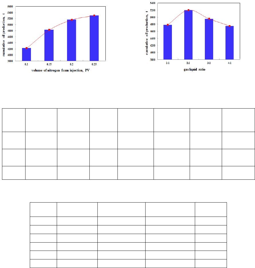
Figure 2: Effect curve of nitrogen foam injection on
cumulative oil production.
Figure 3: Effect curve of nitrogen foam gas liquid
ratio on cumulative oil production.
Table 3: Optimal case table of 4502 well nitrogen foam profile control.
Layer
Effective
thickness
Pore
volume m³
0.2PV
Bubble
underground
volume(m³)
N2
underground
volume m³
Foam
concentrati
on t
N2 above
ground
volume m³
H3Ⅱ2 4.4 4251.32 850.26 283.42 566.84 1.42 33273.51
H3Ⅱ3 6.6 5822.01 1164.40 388.13 776.27 1.94 45567.05
Total 11 10073.33 2014.66 671.55 1343.11 3.36 78840.56
Table 4: The statistics table of nitrogen foam profile control measures effect.
Cycle
Cycle oil
production (t)
Cycle steam
injection volume(t)
Average daily oil
production (t)
Cycle oil-
gas ratio
1 242.88 1100 2.70 0.22
2 350.49 1100 3.89 0.32
3 313.58 1100 3.48 0.29
4 273.79 1100 3.04 0.25
5 250.50 1100 2.78 0.23
total 1431.23 5500 3.18 0.26
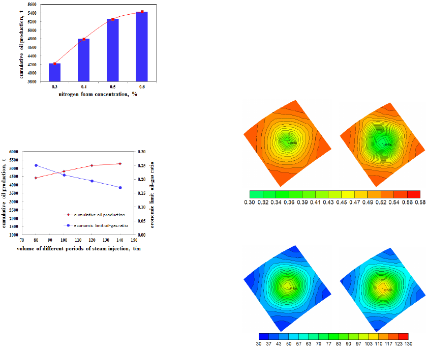
According to the curve between cumulative oil
production and nitrogen foam concentration (Figure
4), with the increase of the concentration, the
cumulative oil production increases. When the foam
concentration is greater than 0.5%, with the foam
concentration continues to increase, the increase of
the cumulative oil production slowed down. As the
foaming agent advances in the strata, the foam
system of the adsorption loss on the rock surface is
occurred, and the liquid film damaged in the process
of profile controlling and oil driving. The stability of
the low-concentration foam system is poor, the
disintegrate speed of liquid film is rapidly, and the
profile controlling and oil driving effect of low-
concentration foaming agent is poor. With the foam
concentration continues to increase, the stability of
the foam system continues to increase. When the
foam concentration reaches 0.5%, the formation of
liquid film has been stable enough. On the basis of
continuing to increase the foam concentration, the
increase of oil production is not obviously.
Nitrogen Foam Profile Control Improves Steam Huff and Puff Development Effect
229
Therefore, the optimum concentration value of
foaming agent is 0.5%.
It can be seen from figure 5. We can find that in
the case of nitrogen foam profile control measures,
when the cycle steam injection volume is between
80t/m-100t/m, the economic limit oil-gas ratio is in
the range of 0.25-0.22. The cycle steam injection
volume is above 120t/m, the economic limit oil-gas
ratio is less than 0.2. Therefore, when the cycle
steam injection volume is 100t/m, the economic
limit oil-gas ratio can be maintained above 0.2 and
the maximum oil production can be obtained at the
same time. So, the cycle steam injection volume of
100t/m is optimized.
In summary analysis, the optimum nitrogen foam
injection parameters are as follows: nitrogen foam
injection volume is 0.2pv, foam concentration is
0.5%, gas-liquid ratio is 2: 1, and cycle steam
injection volume is 100t/m.
Figure 4: Effect curve of nitrogen foam under
concentration on cumulative oil production.
Figure 5: Different periods of gas injection cumulative
oil production, economic vapor ratio curve.
4.3 Development Effect of Nitrogen
Foam Profile Control
According to the optimized optimal nitrogen foam
injection parameters, the nitrogen subsurface usage
is converted to ground consumption according to the
Clapeyron equation. The calibration equations are:
11 1
ZRPV n T= (2)
22 2
ZRPV n T= (3)
According to the 40℃ wellhead temperature, the
surface atmospheric pressure of 0.1MPa, the
subsurface temperature of 100℃, the subsurface
pressure of 7MPa and other data turn to calculation.
That is, the amount of ground nitrogen is equal to
58.7 of the amount of underground nitrogen.(Table 3)
It can be seen from table 4. The oil production
peak of 4502 well was 4.8t in the second rounds,
and after that the daily oil production gradually
decreased with the increase of the profile control
round.
According to the curve of oil saturation variation
and curve of temperature variation(Figure 6-Figure
7), we can find that after 5 rounds of profile control,
the oil saturation value of H3Ⅱ2 oil layers
decreases from 0.43 to 0.37. The oil saturation value
of H3Ⅱ3 oil layers decreases from 0.45 to 0.35. The
average temperature of H3Ⅱ2 oil layers increases
from 50.3℃ to 60.38℃. The average temperature of
H3Ⅱ3 oil layers increases from 51.45℃to 78.41℃.
It is shows that the production measures of nitrogen
foam effectively play the role of profile control and
oil displacement. Meanwhile the production
measures make the steam fully heat the oil layer to
achieve the ideal sweeping effect.
Figure 6: The remaining oil saturation field before or
after profile control.
Figure 7: The temperature field before or after profile
control.
IWEG 2018 - International Workshop on Environment and Geoscience
230
5 CONCLUSIONS
The actual production data of liquid producing
capacity, gas injection volume and water content of
each well are combined. Based on the data of
geological analysis and logging interpretation, 79
wells in XQ-45 block are measured according to the
different parameters such as the remaining oil
saturation and the degree of reserve recovery
establishes the five types remaining oil classification
criteria.
Based on the degree of reserve recovery of the
five type remaining oil wells, the remaining oil
potential evaluation criteria are: the oil wells with
less than 10% degree of reserve recovery have the
high potential of remaining oil, the oil wells with
degree of reserve recovery of 10%-25% have the
medium potential of remaining oil, the oil wells with
more than 25% degree of reserve recovery have the
low potential of remaining oil. It is concluded that
the remaining oil potential of the five heavy oil
wells is as follows: inter-layer differential type>
edge water effected type> fault screened type>
interwell enrichment type> intra-layer differential
type.
According to the inter-layer differential type
remaining oil, the representative well is selected,
and single well geological model is established. The
production status of each layer is combined and the
remaining oil potential is analyzed, the production
plan is designed in layers. Orthogonal test method is
used to carry out the orthogonal experiment design
of the relevant parameters of oil well production
measures. At the same time, the numerical
simulation method is used to carry out numerical
simulation and optimize injection and production
parameters. In this way, combining with the
economic benefit analysis under the current low oil
price, the best solution is obtained by obtaining the
maximum crude output and the economic limit oil
gas ratio greater than 0.2 as the evaluation standard.
Aiming at the high-level intervals in the oil wells
with different layers, then take nitrogen foam profile
control measures to adjust the suction profile, and
optimize the optimal nitrogen foam injection
parameters are: volume of nitrogen foam injection is
0.2pv, foam concentration is 0.5%, gas-liquid ratio
is 2: 1, cycle steam injection volume is 100t/m.
The results show that the oil production is the
largest in the second round of profile control, the
average daily oil production is 3.89t, and the cycle
oil-gas ratio reaches 0.32. On this basis, continue to
increase the profile control round, after the profile
control 5 rounds, the average daily oil production is
3.18t, the average oil-gas ratio is 0.26, the cycle of
cumulative oil production is 1431.23t, and the
program implementation effect is getting better. It
shows that nitrogen foam profile control can
obviously reduce the ineffective and inefficient
channeling of steam in the low remaining oil
saturation zone and improve the development effect
of steam huff and puff.
ACKNOWLEDGEMENTS
This paper is supported by "Thirteenth Five-Year
Plan" National Science and Technology Major
Project (2016ZX05015-002).
REFERENCES
Cao Yanbin, Liu Dongqing and Wang Shantang, et al.
2013 3D physical simulation of steam flooding and
applications in ultra-heavy oil reservoirs of Shengli
oilfield Acta Petrolei Sinica 34(04) 733-739
Cao Zhengquan, Ma Hui and Jiang Na, et al. 2006
Application of nitrogen foam profile control technique
in thermal recovery well in Gudao Oilfield Petroleum
Geologyand Recovery Efficiency 05 75-77+108
Chen Guo, Liao Guangzhi and Niu Jingang 2001 Foam
flow equivalent mathematical model in porous media
Petroleum Geology & Oilfield Development in Daqing
02 72-74+138
Fan Zhicheng, Liu Huiqing and Zhang Hongling, et al.
2009 Laboratory study of nitrogen-foam agents profile
control technology at heavy oil reservoir in Jinglou
Oilfield[J] Oil Drilling & Production Technology
31(02) 74-78
Huseyin Onur Balan 2013 Dynamics of Foam Mobility in
Porous Media The University of Texas at Austin
Islam M R 1989 Mechanics of foam flow in porous media
and applications The Journal of Canadian Petroleum
Technology 12(8) 88-96
Islam M R, MacDonald T A and Farouq S M Ali, et al.
1989 Experimental and numerical study of foam flow
through porous media[A]. Proc. Of the Thrid
International Symposium on EOR Maracaibo,
Venezuela 144-163
Li Zhaomin, Li Binfei and Xu Yonghui, et al. 2007 Study
on the flow-diversion characteristics of foam and its
application Journal of Xi’an Shiyou University(Natural
Science Edition) 02 100-102+106+179
Malcolm Greaves 2004 Air injection-improved oil
recovery strategy for the UK continental shelf The Oil
& Gas Review 34(3) 118-121
Nitrogen Foam Profile Control Improves Steam Huff and Puff Development Effect
231
Rossen W R and Zhou Z H 1994 Modeling Foam Mobility
at the Limiting Capillary LA, Sept. 26-28
Tian Xin 2015 Study on microscopic mechanism and
factors affecting the sealing characteristics for nitrogen
foaming flooding Bulletin Of Science and Technology
31(03) 93-96
Wang Binyu and Zhang Jun 2007 Application of nitrogen
foam profile control technology in saibei oilfield Sino-
Global Energy 04 63-67
Yang Guanglu, Lin Yuqiu and Liu Jialin, et al. 2004 Study
on adaptability of nitrogen foam flooding to heavy oil
reservoir in liaohe oilfield Xinjiang Petroleum Geology
02 188-190
Yang Lei 2014 The research and application of nitrogen
foam conformance treatments optimal design method
Yangtze University
Zhang Liehui, Hu Yong and Tu Zhong, et al. 2000 Foam
flooding experience model and its application Journal
of Southwest Petroleum Institute 03 50-52+3-2
Zhang Sifu, Liao Guangzhi and Zhang Yanqing, et al.
2001 Experimental study on Daqing oilfield foam
compound flooding pilot mine Acta Petrolei Sinica 01
49-53+5-4
Zhang Zhongping, Liu Xiaobo and Li Changheng, et al.
2012 Nitrogen foam improves steam huff and puff
development research on numerical simulation
technology Sino-Global Energy 17(01) 61-65
Zhang Zhongyi, Zhou You and Shen Dehuang, et al. 2012
Physical modeling experiments on steam nitrogen
foam flooding for a vertical and horizontal well
combination Acta Petrolei Sinica 33(01) 90-95
Zhao Renbao, Yue Xiang’an and Ke Wenqi, et al. 2009
Study on influence factors for stability of nitrogen
foam system Acta Petrolei Sinica 30(01) 84-87+91
Zhou Guohua, Song Xinwang and Wang Qiwei, et al.
2006 Application of foam combination flooding in
Shengli Oilfield Petroleum Exploration and
Development 03 369-373
IWEG 2018 - International Workshop on Environment and Geoscience
232
