
Challenges and Strategies of Infill-Drilling Within Large Scale
Hydraulic Fracturing Zone for Shale Gas Due to Geostress
Disturbance
Yijin Zeng
1,2
, Xinming Niu
1,2
, Yanbin Zang
1,2
, Feifei Wang
3
and Zizhen Wang
3,*
1
State Key Laboratory of Shale Oil and Gas Enrichment Mechanisms and Effective Development, Beijing, China;
2
Sinopec Research Institute of Petroleum Engineering, Beijing, China;
3
China University of Petroleum (Huadong), Qingdao, China.
Email: wangzzh@upc.edu.cn.
Keywords: Shale gas, hydraulic fracturing, geostress disturbance, infill-drilling
Abstract: The Fuling shale gas field is planning to reduce the well spacing (600-1300 m at the early development
stage) to about 300m by infill drilling works to accelerate recovery. We first summarized the drilling
troubles and accidents in the early infill-drilling practices in Fuling. And we gave two representative
examples to show the challenges of infill drilling works within geostress disturbance zone. One example is
about gas kick and overflow, and the other is drilling fluid pollution by fracturing fluid from neighbouring
well. Moreover, two practical strategies for these drilling challenges were put forward. The disturbance of
the geostress caused by multistage hydraulic fracturing of neighbouring wells within a drilling units is
numerically simulated to provide data for optimized design of well spacing and well path of the infill
drilling in Fuling shale gas field. Recent infill-drilling practices with the aid of these effective strategies
show much better performances. For example, the average rate of penetration (ROP) of an infill well (Y29-
S1HF) with depth of 4245m reaches 12.02m/h, and no drilling troubles or accident occur.
1 INTRODUCTION
Shale gas becomes more and more importance
worldwide. The shale gas prospecting and
production was started early since 1982. The shale
gas production reached 7500×10
8
m
3
in America at
2016, which made up more that 40% of the total
natural gas production of America (Krisanne et al.,
2011). Horizontal well factory and multistage
hydraulic fracturing are the most important two
technologies for shale gas production commercially.
The well spacing within the same drilling unit is
usually 200-300m in America (Hummes et al., 2012).
Aiming for more scientific design of multistage
fracturing and more efficient fracturing works,
researchers have done lots of studies on the induced
fractures and the geostress redistribution after the
hydraulic fracturing. There are two representative
methods to create fracture networks: the “Commuter
Frac.” method and the “Texas Two-Step” method.
Roussel & Sharma (Roussel and Sharma, 2010)
investigated the geostress redistribution, and
developed the relation between the fracture
propagation pressure and the fracture numbers. Most
of these studies currently are limited to the scale of a
single well. However, several horizontal boreholes
(usually 4-8) within one drilling unit are drilled for
the well factory, and each horizontal section was
fractured stage by stage (Zhang et al., 2014). So the
geostress redistribution is much more complicated
than the conditions in those scientific researches.
Fuling shale gas field, the first and largest
commercially developed shale gas field in China,
now is aiming to reach a production capacity of
1.0×10
10
m
3
per year in 2017. The spacing of two
nearby paralleled horizontal wells is relatively large
at the early development stage of Fuling, mainly
600-1300 meters (Lu, 2013; Zeng et al., 2013). For
such a large spacing, infill drilling is a promising
way to accelerate recovery. However, the geostress
of the interested block has been greatly disturbed by
the multistage hydraulic fracturing of neighboring
wells, which push the infill drilling into great risk
(Niu, 2014).
552
Zeng, Y., Niu, X., Zang, Y., Wang, F. and Wang, Z.
Challenges and Strategies of Infill-Drilling Within Large Scale Hydraulic Fracturing Zone for Shale Gas Due to Geostress Disturbance.
In Proceedings of the International Workshop on Environment and Geoscience (IWEG 2018), pages 552-556
ISBN: 978-989-758-342-1
Copyright © 2018 by SCITEPRESS – Science and Technology Publications, Lda. All rights reserved

2 DRILLING TROUBLES
DURING INFILL-DRILLING
On one hand, the fracturing work created high
productive fractures, which is an effective way for
shale gas production commercially. On the other
hand, it changed the geostress distribution. However,
we have not found an economical and effective way
to assess quantitatively the redistribution of the
geostress. This leads to an embarrassing condition
that we do not know the pore pressure and the stress
where we will drill a new well, which severely
influence the safety of the drilling work, personnel,
and the investments. The drilling practice in Fuling
shale gas field indicated that some well drilling
works were obviously influenced by the large scale
hydraulic fracturing work. Table 1 shows a simple
summary of drilling troubles occurred during the
infill well drilling due to the influence of hydraulic
fracturing.
2.1 Case A: Gas Kick & Overflow
Hydraulic fracturing in the pay zone has a pressure
elevating effect. The pore pressure will increase
after the fracturing work is finished. The natural gas
within the pay zone of the fracturing well would be
driven to the nearby well that is under drilling.
When the gas invades the wellbore under drilling, it
would lead to a gas kick and overflow. If such
drilling troubles are not addressed properly, they
may further grow to a blowout and result in serious
drilling accidents. Moreover, the formation becomes
more sensitive to the drilling parameters due to the
pressure disturbance by hydraulic fracture. The
change of drilling work condition and the
adjustment of drilling parameters also tend to cause
a gas kick or overflow.
For example, the Well Y193-2HF is affected
significantly by the hydraulic fracturing work in a
nearby well. When the Longmaxi formation was
penetrated in Well Y193-2HF, the overflow troubles
totally occurred 23 times, which pushed the drilling
work into great risk. And more than half of these
overflow troubles were encountered after the change
of drilling work condition or the adjustment of
drilling parameters. One gas kick was occurred
when the well was drilling to the depth of 2690m,
the total hydrocarbon value reached 90%. The well
was closed to exhaust the gas by burning. The height
of the fire flame was more than 10 meters, and
continued nearly 4 hours (as shown in Figure 1).
Then the well was open to build circulation. But the
total hydrocarbon value was still abnormal. It
increased obviously after every circulation period,
and finally reached 80% for 20-30 minutes. Trip off
the drill string and change the bottom hole assembly
(BHA). And then trip in the drill string to 2662m to
displace the gas by circulation with the maximum
total hydrocarbon value of 87%. The well was
closed again to exhaust the gas by burning for nearly
2 hours. The maximum height of the fire flame was
about 10 meters.
Table 1: The summary of drilling troubles in wells disturbed by fracturing
Well
Well
depth
(m)
Average
ROP
(m/h)
Drilling
period
(d)
Drilling troubles
Percent of non-
productive time
(%)
Y39-2-1 4845 8.74 65.50
Loss circulation 1 time
Overflow 1 time
2.60
Y11-2-1 4155 6.86 68.13
Loss circulation 1 time
Overflow 9 times
3.18
Y7-1HF 4130 7.35 58.83 Overflow 1 time 4.11
Y39-1HF 4350 7.26 64.46 Overflow 23 times 21.04
Y46-2HF 4550 9.79 49.61
Gas kick 1 time
Pipe breaking 1 time
Overflow 1 time
13.00
Y22-3HF 4680 8.74 112.35
Loss circulation 7 times Overflow 1
time
Sticking pipe 1 time
52.82
Challenges and Strategies of Infill-Drilling Within Large Scale Hydraulic Fracturing Zone for Shale Gas Due to Geostress Disturbance
553
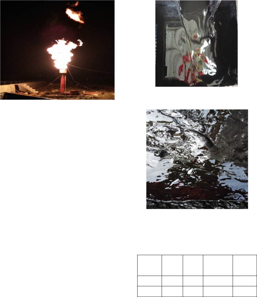
Figure 1: The field picture of burning the gas kick in Well
Y193-2HF.
2.2 Case B: Drilling Fluid Polluted By
Fracturing Fluid From
Neighbouring Well
When the infill-well was drilling, the infill-well
would be connected to the fractures of the
neighbouring well if the drilling work of the infill-
well and the fracturing work of the neighbouring
well were conducted at the same period of time. So
the fracturing fluids of the neighbouring well would
invade into the infill well under drilling, and the oil-
based drilling fluid would be polluted. This will
degrade the properties of the drilling fluid, such as
the rheology, filter loss, and emulsion-breaking
voltage, which would further affect the safety of
drilling works.
For example, the Well Y39-1 is affected by the
fracturing work of a neighbouring well. The
performance of the oil-based drilling fluid was
significantly deteriorated due to the invasion of the
fracturing fluid from the neighbouring well.
Measurements at the work site indicated that the
density of the drilling fluid decreased by 2.2%, the
viscosity increased as high as 85%, the emulsion-
breaking voltage decreased by 48.5%, and the
oil/water ratio (OWT) decreased by 23.5%. The
properties of drilling fluid of the Well Y39-1 before
and after the pollution are shown in Table 2. Figure
2 and Figure 3 are the pictures of the drilling fluid
before and after the pollution taken at the work site,
respectively.
Figure 2. The drilling fluid of Well Y39-1 before
pollution.
Figure 3: The drilling fluid of Well Y39-1 after
pollution.
Table 2: The drilling fluid properties of Well Y39-1
before and after the pollution
Properties
Density,
ρ
(g/cm
3
)
Viscosi
ty
*
,
η
(s)
Emulsion-
breaking
Voltage, U
(V)
Oil/water
ratio (%)
Before
p
ollution
1.38 70 875 85/15
After
p
ollution
1.35
130-
trickle
450 65/35
*
The viscosity is measured by the Marsh funnel
viscosimeter at 20 ℃ according to the API standard.
IWEG 2018 - International Workshop on Environment and Geoscience
554
3 STRATEGIES
3.1 Numerical Simulation of Pore
Pressure Redistribution
As the development of computers, numerical
simulation has become a popular method to give
predictions as important complements to experiment
measurements and field monitoring. In order to
further investigate how far and to what extent the
pore pressure had been changed, we carried out
dynamic numerical modeling of pore pressure
redistribution by finite element method. The
numerical modelling can be done by the ABAQUS.
Parameters used in these modellings are shown in
Table 3. Firstly, we build 2D geometrical model of a
drilling unit with four parallel horizontal wells, and
then we dynamically simulate the pore pressure
change due to multistage fracturing. For such
modeling, we considered the interaction between
fractures and wells. We can also numerically test the
effect of the well spacing, fracturing pump pressure,
stage interval, and fracture length on the induced
geostress change.
Table 3: The values of parameters used in the numerical
modellings.
Properties
V
alue
The effective coefficient of
compressibility of the shale,
C
(Pa
-1
)
0.05×10
-9
Porosity,
φ
(%)
2%
The density of the shale,
ρ
(g/c
m
3
)
2.48
The Poisson’s ratio, ν
0.234
The viscosity of the fracturing fluid,
η
f
(Pa.s)
0.001
Pressure of the gas reservoir,
P
p
(MPa) 25
Differential pressure for production, ΔP
(
MPa
)
20
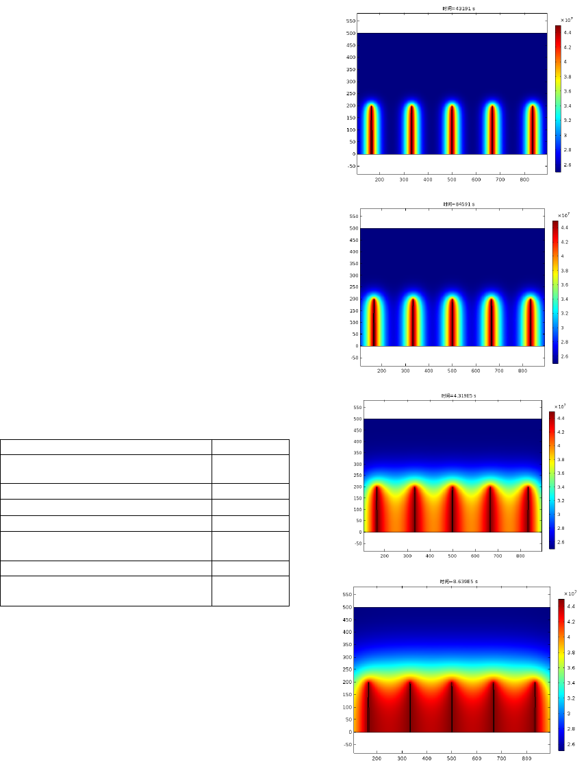
Figure 4 gives the modelling results of pore
pressure redistribution after a five-stage fracturing in
horizontal section. It shows that the influence zone
of pore pressure is gradually extended with the
duration time of fracturing and well shut-off. For
this example, the pore pressure disturbance reached
as far as 91m in x direction, and 75m in y direction
after 24 hours since the hydraulic fracturing work
has been finished.
(
a
)
t=12h
(
b
) t=24h
(c) t=120h
d
)
t=240h
Figure 4. Pore pressure (unit: Pa) redistribution at
different times after a five-stage fracturing in horizontal
section.
Challenges and Strategies of Infill-Drilling Within Large Scale Hydraulic Fracturing Zone for Shale Gas Due to Geostress Disturbance
555
3.2 Optimization of Well Spacing and
Well Path
For infill well drilling, it is important to optimize the
well spacing. We need an appropriate well spacing
to enhance the recovery with an economical number
of wells. But assuring the safety of infill well
drilling work should be the first priority. Based on
results of the numerical modelling of pore pressure
redistribution of the neighbouring well, we divided
the geostress disturbance area into three parts
according to the disturbance level. These results are
used for optimized design of well spacing and well
path. Usually, we should check the following
questions when we make the design:
Would the infill well go through the geostress
disturbance zone?
If yes, is it possible to avoid? If this can not be
avoided, how to minimize the length of the affected
section?
If not, which well spacing should be the best?
After optimization, we need appropriate bottom
hole assembly (BHA) and monitoring techniques to
ensure that the drill bit is go along the predesigned
well path as well as possible.
Recent drilling practices of infill well within the
Fuling shale gas field demonstrated that these two
strategies are effective to reduce the drilling troubles
and improve the drilling efficiency. For example,
after the application of these strategies, the average
ROP of an infill well (Y29-S1HF) with depth of
4245m reaches 12.02m/h, and no drilling troubles or
accidents occur.
4 CONCLUSIONS
We first summarized the drilling troubles and
accidents in the early infill-drilling practices in
Fuling shale gas field, and gave two representative
examples. Then two practical strategies for these
drilling challenges were put forward. And the
strategies were proven to be effective by current
infill drilling practices. Based on this study, we can
conclude that:
Wide application of hydraulic fracturing in
Fuling shale gas field have changed the geostress
significantly. Such kind of geostress disturbance
currently still can not be assessed quantitatively with
its economic and effectiveness, which push the infill
drilling into great risk.
Gas kick, overflows, loss circulation, pipe
sticking and breaking are the main drilling troubles
due to geostress disturbance. And sometimes, the
drilling fluid can be polluted by the fracturing fluid.
The numerical modeling of pore pressure
redistribution after fracturing helps us to better
understand the current geostress distribution.
Optimized design of well spacing and well path
with the aid of numerical simulation of pore
pressure redistribution is an effective way for the
infill drilling.
ACKNOWLEDGEMENTS
This study is supported by the State Key Laboratory
of Shale Oil and Gas Enrichment Mechanisms and
Effective Development (No. ZC0607-0016).
REFERENCES
Hummes O, Bond P R, Symons W and Jones A, et al.
2012 Using advanced drilling technology to enable
well factory concept in the Marcellus shale.
IADC/SPE Drilling Conference and Exhibition, 6-8
March, San Diego, California, USA, SPE 151466
Krisanne K L, Weissert S, Jackson J B and Marcotte D
2011 Marcellus shale hydraulic fracturing and optimal
well spacing to maximize recovery and control costs.
SPE Hydraulic Fracturing Technology Conference,
24-26 January, The Woodlands, Texas, USA, SPE
140463
Lu Baoping 2013 Sinopec engineering technical advances
and its developing tendency in shale gas Petroleum
Drilling Techniques 41 1
Niu Xinming 2014 Drilling technology challenges and
resolutions in Fuling shale gas field Petroleum
Drilling Techniques 42 1
Roussel N P and Sharma M M 2010 Role of stress
reorientation in the success of refracture treatments in
tight gas sands SPE Production & Operations 27 346
Zeng Fanhui, Guo Jianchun, Liu Heng and Xiao Yong
2013 Experience of efficient fracturingof shale gas in
North America and enlightenment to China Journal of
Southwest Petroleum University (Science &
Technology Edition) 35 90
Zhang Jincheng, Sun Lianzhong, Wang Jiachang and
Zang Yanbin 2014 Application of multi-well pad in
unconventional oil and gas development in China
Petroleum Drilling Techniques 42 20
IWEG 2018 - International Workshop on Environment and Geoscience
556
