
Thermo-Fluid-Solid Coupling Analysis in the Steam
Generator of a High Temperature Gas Cooled Reactor
W Afsar
*
, J Cai and S S Cui
School of Nuclear Science and Engineering, North China Electric Power University,
Beinong Road, Huilongguan, Changping District, Beijing, China, 102206
Corresponding author and e-mail: W Afsar, wajahatafsar98@yahoo.com
Abstract. This paper is about the high temperature gas cooled reactor (HTGR-10) of China
which is an experimental reactor. The thermo-flu id-solid coupling analysis for the steam
generator of HTGR is performed in wh ich the steam generator is modelled and then tested for
some boundary conditions. The analysis is of key impo rtance as Steam generator is very
crucial component of a power plant system that ensures the safety and efficiency of a plant.
To predict the thermal distribution in the tubes of a steam generator the coupled heat transfer
between the primary and secondary sides must be considered. ANSYS Fluent is used for
analysis that employs finite element method to achieve the task. The temperature distribution
within the steam generator is analysed. The resulting temperature profile, pressure profile and
the velocity profile for the coolant and feedwater is determined. In static structural analysis
equivalent stress, equivalent elastic strain and the total deformat ion produced in the tube
under such conditions is calculated. We see that the temperature of feedwater increases
continuously as it moves upward in the tube while the coolant (He gas) temperature decreases
as it goes down through the shell. The pressure of a coolant decreases as it flows downwards
in the shell and consequently its velocity increases in the said direction. The velocity of a
feedwater increases gradually as it rises up in the tube due to gradual decrease in its pressure.
The equivalent stress, equivalent elastic strain and the total deformation produced in a tube
are highly dependent on system temperature, tube material and the geometric configuration of
tube.
1. Introduction
High temperature gas-cooled reactors can serve as possible energy generation source as well as the
process heat source at different temperatures. Due to simultaneous production of electricity with the
recovery and utilization of heat the plant can acts as a combined heat and power plant. Some of the
unique features of this type of plant include its inherent safety, passive heat removal system for
residual heat, graphite reactor core, free from corrosion problems, eliminates risk of fuel coolant
interaction due to coated fuel particles, non-radioactive coolant, higher conversion efficiency and a
lower power density [1, 2].
No doubt while talking about nuclear reactors one of the most important concern that quickly
comes in mind is the safety of a plant as there have been some of the serious accidents in the past
history that have left very tragic after-effects. However, HTGR is considered as an excellent
236
Afsar, W., Cai, J. and Cui, S.
Thermo-Fluid-Solid Coupling Analysis in the Steam Generator of a High Temperature Gas Cooled Reactor.
In Proceedings of the International Workshop on Materials, Chemistry and Engineering (IWMCE 2018), pages 236-242
ISBN: 978-989-758-346-9
Copyright © 2018 by SCITEPRESS – Science and Technology Publications, Lda. All rights reserved
candidate in terms of safety features [2, 3]. Therefore, HTGR can be considered as a better future
option for energy production.
HTGR-10, a generation IV reactor concept and the first step of China towards modular HTGR
development, is an experimental pebble bed reactor of 10 MW located at Tsinghua University in
Beijing. For every reactor steam generator is a crucial component. The steam generator design of
HTGR-10 consists of a helically coiled tubes and is once through steam generator. Helically coiled
tubes are far more efficient than the straight ones because of their higher heat transfer rates as
secondary flow is forced by centrifugal force. Additionally this type of heat exchanger has compact
size and a large surface area per unit volume [4].
The critical step is to understand the temperature non-uniformity of a steam generator as the
thermal non-uniformity will affect the other parameters. Large thermal non-uniformity and the
resulting high temperature will damage the structure. Therefore, thermo-fluid-solid coupling analysis
is of critical importance for the operation and safety of a plant.
2. Modelling and simulation of steam generator of HTGR-10
The steam generator of HTGR-10 is once through, vertically aligned and counter flow shell and tube
type heat exchanger. The primary fluid is helium gas which is used as a coolant and the secondary
fluid is water. The material of helical tubes is 2.25Cr1Mo steel owing to withstand at a high
temperature of about 750 °C. The different heat capacity of superheated and liquid water regions may
generate ruptures and creeps in different layers of tube. That’s why the studies for the temperature
non uniformity within the steam generator is of significant importance which provides the basis for
the design and the construction of this critical component of a plant. Helium gas being coolant will
transfer its heat, almost totally by convection, through helical tubes to the feedwater and returns back
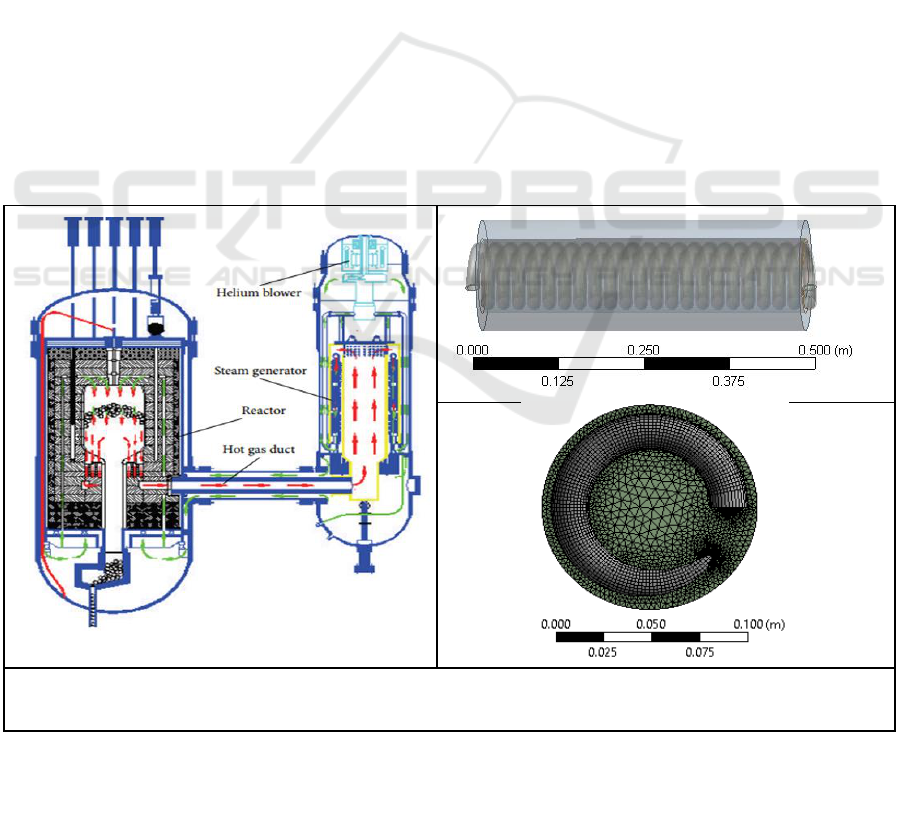
to the core. The primary system and the flow path of helium is depicted in Figure 1 (a).
(a)
(b)
(c)
Figure 1. (a) Primary system of HTGR-10, (b) geometric model of the steam generator, and (c)
the front view of a steam generator after meshing.
On the basis of steam generation there are three sections of steam generator i-e pre-boiling region,
boiling region and the superheated region which constitutes the complicated geometry of the steam
generator and to model the entire geometry demands enough memory and hardware capacity. So, just
Thermo-Fluid-Solid Coupling Analysis in the Steam Generator of a High Temperature Gas Cooled Reactor
237

the pre-boiling region is modelled and analyzed. The geometric model of the steam generator is
shown horizontally in Figure 1 (b) that consists of tube and shell which is developed using
SolidWorks software. The height of the steam generator for the pre-boiling region is about 0.5 meter,
the tube diameter is 18 mm and the inner diameter of the casing tube (shell) is 139 mm. The helical
ascent angle is 3.66
o
which results in a total of 22 number of turns for a pre-boiling region. Some of
the structural parameters of the steam generator are shown in Table 1.
The model is then imported to Ansys for the required analysis. Here the tube is filled with water and
the space between the tube and the shell is filled with helium gas. Figure 1 (c) shows the top view of
the steam generator that includes the tube and the gas in meshed form while the shell body is suppressed.
The mesh result generates about 2.9 million elements on which simulation is performed. One mesh
interface in our model is the tube inner surface and the feedwater interface while the other one is the tube
outer surface and the helium gas both of which are thermally coupled. Fluent module of Ansys is used to
perform thermo-fluid-solid coupling analysis that employs the pressure velocity coupling method via
SIMPLE algorithm for fluid flow and finite element method for both the steady-state thermal and static
structural analysis. The finite element method is a numerical technique for finding approximate solutions
for both partial differential equations and integral equations.
Some of the process parameters for the steam generator of HTGR-10 are shown in Table 2.
Boundary conditions for both the primary and secondary sides are chosen at 50% of rated load as shown
in Table 2. As mentioned previously our model just covers the pre-boiling region of the steam
generator and hence the inlet temperature of the helium gas is chosen to be 350°C while the primary
pressure is 3 MPa. The water inlet temperature is 104 °C while its pressure is chosen to be 4.59 MPa.
The inlet velocities of both the coolant and feedwater are calculated using mass flow rates as shown
in Table 2.
Table 1. Structural parameters of Steam Generator.
Parameters
Unit
Value
Helical ascent angle
Degree
3.66
Heater outer diameter
mm
18
Heater helical diameter
mm
112
Vertical tube pitch
mm
22.5
Central tube outer diameter
mm
83
Casing tube inner diameter
mm
139
Heater length
m
31.82
Heater total height
m
3.96
Table 2. Process parameters of Steam Generator.
Parameters
Value at 30% of rated load
Value at 50% of rated load
Primary pressure (M Pa)
3.0
3.0
Helium inlet temperature (°C)
643
661
Helium outlet temperature (°C)
194
212
Helium flow rate (kg/h)
125
208
Feedwater pressure (M Pa)
4.21
4.59
Feedwater temperature (°C)
104
104
Steam exit pressure (MPa)
4.0
4.0
Steam exit temperature (°C)
440
440
Steam flow rate (kg/h)
102
102
IWMCE 2018 - International Workshop on Materials, Chemistry and Engineering
238
3. Results and discussion
In heat exchanger the fluids exchange energy without being mixed by means of solid wall. Thus, this
solid wall plays a key role in the performance of a steam generator. Heat is exchanged between the
fluids mesh by mesh and a good mesh leads to a better solid fluid interaction. Results include the
temperature distribution within the shell and tube of a steam generator, the pressure and the velocity
profile of both helium gas and feedwater, all of which are highly dependent on one another. While in
static structural analysis, stress, strain, and the resulting total deformation produced in a tube are
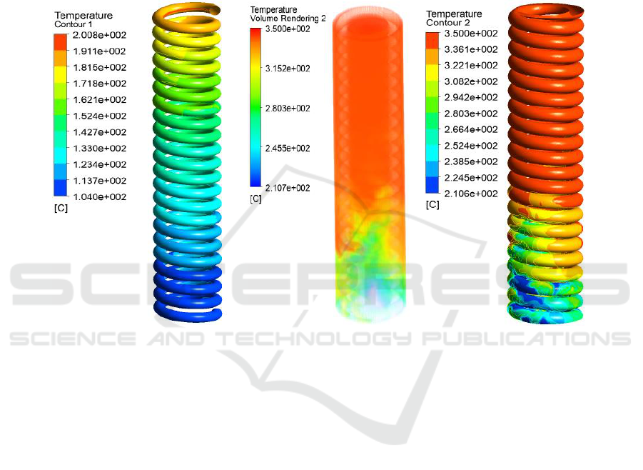
calculated and analyzed. The temperature profile of feedwater and coolant is shown in Figure 2.
(a) (b) (c)
Figure 2. Temperature distribution of feedwater (a) within helical tube, (b) of helium gas in shell
side of steam generator, and (c) of helium gas that is in contact with the helical tube.
From the results we see that the heat transfer between the downward flowing helium gas and the
upward flowing feedwater results in a greater temperature difference at the inlet and outlet of
feedwater as its temperature gets elevated from 104°C to about 191°C which is enough for a pre-
boiling region as shown in Figure 2(a) and on comparing the above case (a) and case (c) we see that
the temperature of external tube wall is higher than that of internal tube wall. The inlet temperature of
a helium gas which is 350°C, as our model includes just the pre-boiling region and not the whole
steam generator, doesn’t change much until it comes down where after transferring its heat to
feedwater becomes 280°C and finally 210°C at the outlet as shown in Figure 2(c) which is in
accordance to Table 2. In the whole phenomena heat transfer is accomplished by forced convection.
The results are in accordance with those of Ref. [5-7].
Our next results (pressure and velocity) are highly dependent on the previous temperature results.
The pressure and the velocity of both the coolant and feedwater plays an important role in the process
of heat transfer especially the velocity of coolant which determines the rate of heat transfer. The
velocity of feedwater is lower compared to the helium gas as the feedwater takes some time to absorb
heat from coolant. The pressure profile of a coolant which is in contact with the tube and the velocity
profile for both the coolant and feedwater is shown in Figure 3.
The pressure of a coolant decreases as it flows downwards in the shell as shown in Figure 3(a)
and consequently its velocity increases in the same direction which is in accordance with the
Thermo-Fluid-Solid Coupling Analysis in the Steam Generator of a High Temperature Gas Cooled Reactor
239
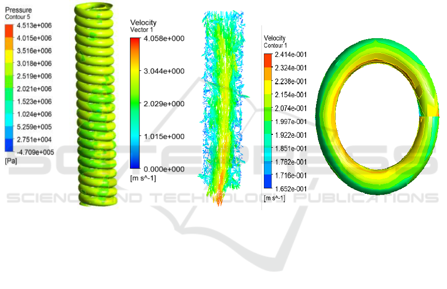
Bernoulli’s principle. From Figure 3 (b) we see that the velocity of a helium gas flowing vertically
downward in a steam generator shows that near the wall of a shell the velocity is almost same and
lower compared to the inner region where its velocity is higher. This is expected because pressure of
a helium gas decreases as it goes down. On the other hand the velocity of a feedwater shows a slight
variation owing to have its slow inlet speed which is 0.18 m/s and also, this is just the pre-boiling
region where the water remains in its liquid state. Here the water close to the wall of a tube has lower
velocity compared to the inner fluid in tube as shown in Figure 3 (c). This satisfies the no-slip
boundary condition somehow as the solid and the fluid have also a minor mutual attraction. However,
the trend for the velocity of a feedwater is that, it increases slightly as the feedwater starts flowing up
in the tube following by a slight decrease in its pressure in the same direction which is not shown
here.
(a) (b) (c)
Figure 3. Pressure distribution of a helium gas which is in contact with the tube (a), Velocity
distribution of helium gas within shell side of steam generator (b), and velocity of a feedwater in a
ring of a helical tube (c).
The above results have considerable impact on static structural analysis parameters. For static
structural analysis the equivalent stress, equivalent elastic strain, and the total deformation produced
in tube is calculated. This analysis will lead to the improved geometry and material selection for
steam generator and consequently increasing the life time of a heat exchanger. The results of this
analysis are shown in Figure 4.
The contour plot for the equivalent stress shows that the upper and lower portion of the tube,
nearby the inlet and outlet, the tube experiences the higher stresses. This is shown in Figure 4 (a)
along with the maximum and minimum points. The reason for higher stress at these portions of the
tube is that they are fixed under such condition. For total deformation we see that it is highest at the
central section of tube as cleared from the colored contours while there is less deformation at the inlet
and the outlet as shown in Figure 4 (b). The results for the equivalent elastic strain depicts that the
tube is experiencing more strain at its top and lower section compared to middle one as shown in
Figure 4 (c) along with maximum and minimum points.
IWMCE 2018 - International Workshop on Materials, Chemistry and Engineering
240
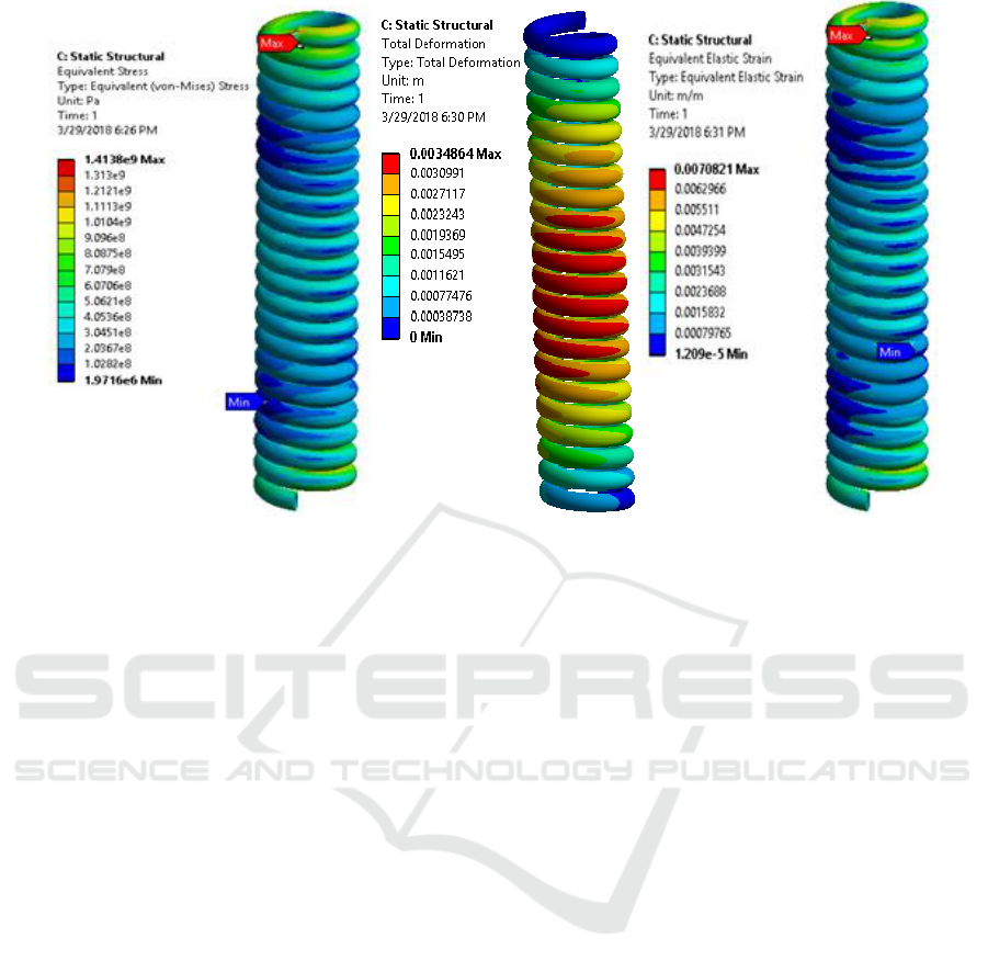
(a) (b) (c)
Figure 4. For helical tube: The equivalent stress (a), total deformation (b), and the equivalent elastic
strain (c).
4. Conclusions
In the energy sector high temperature gas cooled reactors can serve as one of the best option for
energy production owing to have some unique features. In this work the performance of a steam
generator of HTGR-10 is tested by thermo-fluid-solid coupling analysis using Ansys Fluent. It is
concluded that solid fluid interaction studies plays a vital role in predicting the behaviour and
performance of any type of steam generator. The analysis provides a better way to analyze the
structural and flow properties within the steam generator. Structural analysis is important to
determine displacements, stresses and strains. This helps to locate the regions which are under higher
or lower stresses and obviously will be helpful in determining the suitable geometry and material
selection for a steam generator. This analysis can be proved to be very helpful for all steam
generators irrespective of the model and the type of reactor. It can also be very helpful to test a
variety of materials for the tube of a steam generator under different conditions. Furthermore, more
exact and complete results can be obtained by modelling the whole steam generator.
Acknowledgment
This work is supported by National Natural Science Foundation of China and the Fundamental
Research Funds for the Central Universities.
References
[1] Zhang Z Y, Wu Z X, Sun Y L, and Li F 2006 Design Aspects of Chinese Modular High-
temperature Gas-cooled Reactor HTR-PM Nucl. Eng. Des. 236(5-6) 485-490.
[2] Lohnert G 1990 Technical Design Features and Essential Safety-related Properties of the
HTR-Module Nucl. Eng. Des. 121(2) 259-275
[3] Wu Z, Lin D and Zhong D 2002 The design features of the HTR-10 Nucl. Eng. Des. 218, 25.
[4] Cong T L, Tian W X, Qiu S Z and et al 2013 Study on secondary side flow of steam generator
with coupled heat transfer from primary to secondary side J. Applied thermal engineering:
Thermo-Fluid-Solid Coupling Analysis in the Steam Generator of a High Temperature Gas Cooled Reactor
241

Design, processes, equipment, economics 61(2) 519-530
[5] Li X W, Wu X X, He S Y and Luo X W 2012 Thermal Analysis of a Helical Tube Once
Through Steam Generator of Htgr ht2012-58146
[6] Cengiz Y, YasarB and Dursun P 1997 “Heat transfer and pressure drops in a heat exchanger
with a helical pipe containing inside springs” Energy Convers Manage vol.38 619–624
[7] Ju H M, Zuo K F, Liu Z Y and Xu Y H 2001 Two Phase Flow Stability in the HTR-10 Steam
Generator TSINGHUA SCIENCE AND TECHNOLOGY ISSN 1007-0214 16/20 pp75 - 79
Volume 6 Number 1 March
IWMCE 2018 - International Workshop on Materials, Chemistry and Engineering
242
