
Parametric Modeling of Single-stage Double-suction
Centrifugal Pump Housing
L J Du
1
, Y Y Wang
2
, C H Li
2
, J Liu
2
, X R Chu
1, *
and J Gao
1
1
School of Mechanical, Electrical&Information Engineering, Shandong University,
Weihai, Weihai 264209, Shandong, China
2
Shandong Shuanglun Co., Ltd., Weihai 264203, China
Corresponding author and e-mail: X R Chu, xrchu@sdu.edu.cn
Abstract. In this work, a GS single-stage double-suction centrifugal pump is used to study
the method of three dimensional parameterize modeling. Based on the development of the
centrifugal pump shell template, when the thickness changes, it is unnecessary to rebuild the
whole model manually, the pump shell can be rebuilt rapidly by the equation which shortens
the product design and development cycles. Based on the developed model, the strength of
the pump shell under the design conditions was studied through numerical simulation and the
optimized shell thickness was obtained, which saves materials and reduces design cost.
1. Introduction
The single-stage double-suction centrifugal pump adopts a horizontal mid-open type structure and
it’s easy to maintain. It also has the advantages of small NPSH, large flow, and convenient
replacement of the shaft sleeve. Therefore, the single-stage double-suction centrifugal pump is the
most widely used pump in the industry. The wall thickness of centrifugal pump body is usually
designed based on traditional theory and empirical formula. Generally, the thicker the thickness is,
the safer and more durable it is. If the shell strength can meet the requirements, reducing the
thickness of the shell will save a large amount of raw materials. Thereby increasing economic
efficiency and increasing the market competitiveness for enterprises [1]. However, the structure of
single-stage double-suction centrifugal pump housing is complex. When three-dimensional modeling
is carried out, modifying one parameter will lead to reconstruction of the entire model, which is time-
consuming and laborious, and delays the design and development cycle of the product. Therefore, it
is very important to study a parametric modeling method which can quickly modify the wall
thickness and greatly increase work efficiency [2-3].
2. Analysis of single-stage double-suction centrifugal pump shell structure
2.1. Function of centrifugal pump pressure chamber
Centrifugal pump pressure chamber is important fluid flow component located behind the impeller
and is the main part of the pump. The main function of the pressure chamber is as follows [4]:
(1) Collect the liquid from the impeller and transport the liquid to the discharge port or the
impeller inlet of the next stage;
Du, L., Wang, Y., Li, C., Liu, J., Chu, X. and Gao, J.
Parametric Modeling of Single-stage Double-suction Centrifugal Pump Housing.
In Proceedings of the International Workshop on Materials, Chemistry and Engineering (IWMCE 2018), pages 243-249
ISBN: 978-989-758-346-9
Copyright © 2018 by SCITEPRESS – Science and Technology Publications, Lda. All rights reserved
243
(2) Eliminate the rotational movement of liquid from the impeller and convert it into pressure
energy as much as possible;
(3) Reduce the flow rate and reduce the hydraulic loss;
(4) Ensure the liquid flowing from the impeller is axisymmetric, so that the impeller has stable
relative motion and reduces hydraulic loss.
2.2. Function of centrifugal pump suction chamber
The overflow component from the inlet flange of the pump to the inlet of the impeller is the suction
chamber of the centrifugal pump [5]. The main function of the suction chamber is to provide a good
flow field condition at the inlet of the impeller, that is, to ensure that the velocity of the liquid
entering the impeller is stable, the velocity distribution is uniform, the speed is appropriate, and the
flow direction meets the requirements, which reduce the hydraulic loss. In general, the flow rate of
liquid in the suction chamber is small, the hydraulic loss of the suction chamber is far less than the
hydraulic loss of the pressure chamber. However, the flow state in the suction chamber will affect the
flow state of the liquid in the impeller, mainly affecting the cavitation performance of the pump. For
the efficiency of the pump, although the absolute value of the hydraulic loss is not large, but due to
its large proportion of the lift of the low lift pumps, the flow state influence in the suction chamber is
more important than that of the high lift pump.
3. Parametric modeling of centrifugal pump housing based on solid works
3.1. Pressure chamber parameterization modeling
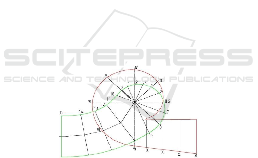
The plane projection diagram of Single-stage double-suction pump pressure chamber and suction
chamber is shown in Figure 1. The red line part is the pressure chamber, and the green line part is the
suction chamber.
Figure 1. Plane projection diagrams of pressure chamber and suction chamber.
The main modeling steps are as follows:
(1) Draw a sketch of eight sections. First, establish a sketch datum plane with 8 sections (I-VIII).
The front reference plane, top reference plane, and right reference plane are the basic work planes.
With the origin as the center, 8 planes perpendicular to the front reference plane are created, and the
8 planes are set to 45° each other. According to the geometric characteristics of the pressure chamber
cross-section on the hydraulic diagram, the sketches of 8 sections were drawn.
IWMCE 2018 - International Workshop on Materials, Chemistry and Engineering
244
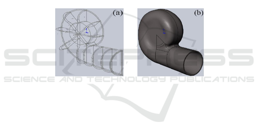
(2) Determine the position of section IX to XII and draw the corresponding sketches. The sketch
planes of the IX to XII sections were created according to the pump hydraulic diagram, and the
corresponding cross-sectional shapes are drawn on the created reference planes as shown in Figure 2a.
(3) Establish the surface of the inner wall of the pressure chamber from sections I to VIII and
section IX to XII. Use the inner edge of each sketch as a surface loft, draw the dividing line
projection onto the surface, and remove the edge surface. Use three-dimensional sketches to connect
the above scattered surfaces with splines and arcs, then use three-dimensional sketches as boundaries
to make boundary surfaces.
(4) Fill the surface between the boundary surface and the loft surface, and then stitch all the
curved surfaces to form half part of the interior of the pressure chamber. Then, half of the inner wall
is mirrored with the front reference plane. Finally, all the surfaces are stitched again to form a
pressure chamber inner wall.
(5) The outer wall of the pressure chamber is similar to the inner wall, but the lofted surfaces and
scanned surfaces are all based on the outer sketches. After drawing the outer wall entity of the
pressure chamber, the Boolean operation between the inner and outer wall is made into a cavity
entity, forming a shell that can be supplied by the fluid. The obtained suction chamber entity is
shown in Figure 2b.
Figure 2. a) Section sketch of pressure chamber. b) Pressure chamber entity.
3.2. Suction chamber parameterization modeling
The three-dimensional shape of the suction chamber spiral section consists of 12 sketch cross-
sections from 0 to 11, the diffusion section consists of 12 to 14 cross-sections and the inlet section of
the suction chamber (section 15). The main steps are similar to the modeling process of the pressure
chamber:
(1) Sketch the 12 sections of the spiral section. First, establish a sketch datum plane with 12
sections (0-11). The front reference plane, top reference plane, and right reference plane are the basic
work planes. With the origin as the center, 12 planes perpendicular to the front reference plane are
created, and the 12 planes are set to 22.5° each other surface. According to the geometric
characteristics of the suction chamber cross-section on the hydraulic diagram, the sketches of 12
sections were drawn.
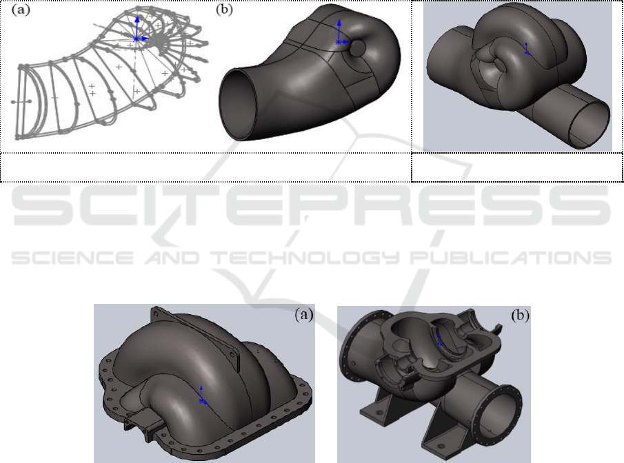
(2) Determine the position of section 12-15 and draw the corresponding sketches. The sketch
planes of the 12-15 sections were created according to the pump hydraulic diagram, and the
corresponding cross-sectional shapes are drawn on the created reference planes as shown in Figure 3a.
(3) Establish the curved surface of the inner wall of the suction chamber from sections 0-11,
sections 12-15. Use the inner layer of each sketch as a surface loft, draw the dividing line projection
onto the surface, and remove the edge surface. Use three-dimensional sketches to connect the above
scattered surfaces with splines and arcs, then use three-dimensional sketches as boundaries to make
boundary surfaces.
Parametric Modeling of Single-stage Double-suction Centrifugal Pump Housing
245
(4) Fill the surface between the boundary surface and the loft surface, and then stitch all the
curved surfaces to form half part of the interior of the suction chamber. Then, half of the inner wall is
mirrored with the front reference plane. Finally, all the surfaces are stitched again to form a solid
wall body.
(5) The outer wall of the suction chamber is similar to the inner wall, but the lofted surfaces and
scanned surfaces are all based on the outer sketches. After drawing the outer wall entity of the
suction chamber, the Boolean operation between the inner and outer wall is made into a cavity entity,
forming a shell that can be supplied by the fluid. The obtained suction chamber entity are shown in
Figure 3b.
(6) Using the curved surface cutting function, the wall of the suction chamber was cut off by the
outer wall of the pressure chamber, and the modeling of the pressure chamber and the suction
chamber of the double suction pump were finally completed as shown in Figure 4.
Figure 3. Suction chamber a) Section sketch b) entity.
Figure 4. Combined entity.
3.3. Parametric modeling of other parts
For the other parts, like flanges, lifting lugs, according to the geometric parameters on the hydraulic
diagram, they are created based on the normal modelling operations like draw a sketch, and use the
extrude boss function to build the solid. Finally, the pump is divided into a pump cover (as shown in
Figure 5a) and a pump body (as shown in Figure 5b) by the top reference plane.
Figure 5. a) Pump cover. b) Pump body.
3.4. Parametric Modeling of pump Shell Thickness
In order to simplify the parametric modeling method, geometric constraints and dimensional
constraints are used to define the geometric sketch completely, instead of using the point position
coordinate. Hence, a parametric drive model was created based on the above constrain definition.
The one-to-one correspondence relation between the housing shell thickness and the dimensions of
other sketches was established and the establishment of the pump housing shell parameter 3D solid
template was completed.
IWMCE 2018 - International Workshop on Materials, Chemistry and Engineering
246
In SolidWorks, it is simple and quick to modify the thickness of the model by equations, which
can shorten the pump modeling time. As follows, the details of adding a size equation can be divided
into the two following steps:
(1) Select the pump shell thickness as the key parameter of the drive model, and set as the
independent variable, and the rest parameters related to shell thickness were defined as dependent
variables.
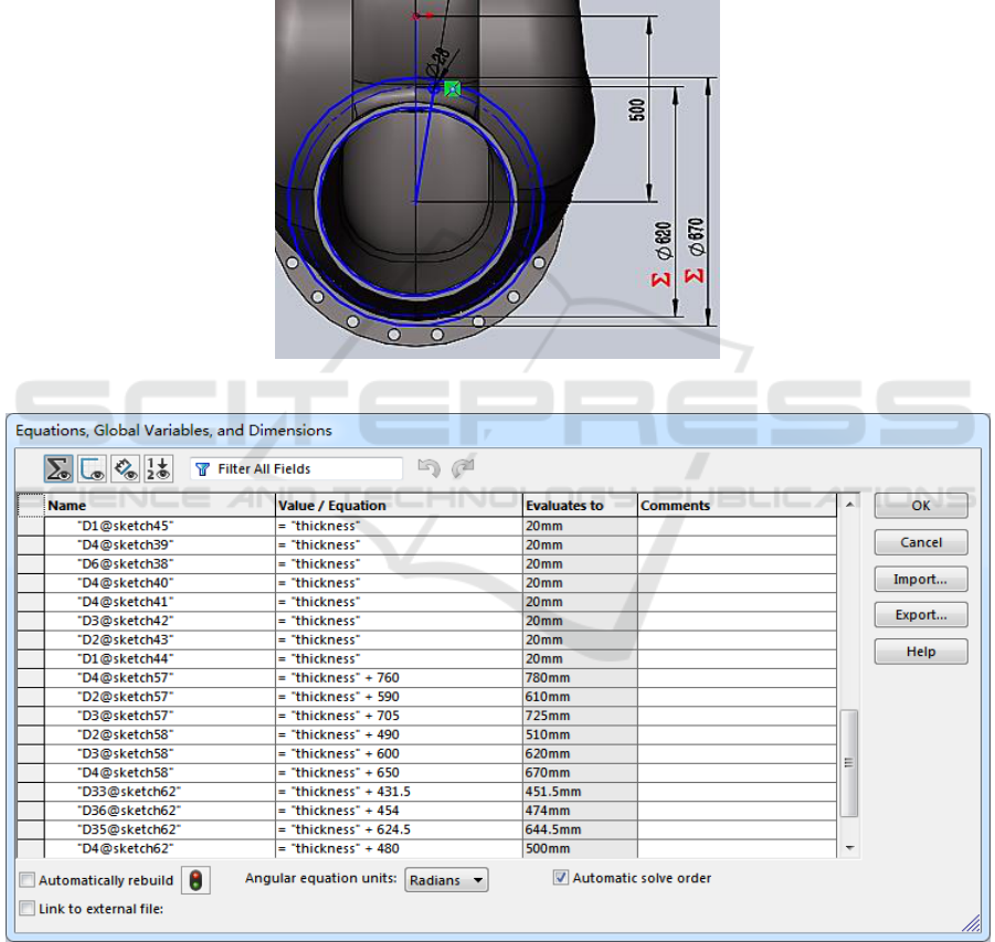
(2) Opening SolidWorks equation command options, set the global variable ‘thickness’ as 20mm,
and define the equation relation of all the thickness-related dimensions of the sketches between the
pump thickness. Taking the inlet flange as an example, the outside diameter of the flange is set to
‘thickness’ +600 (as shown in Figure 6). Some of the parametric equations were shown in Figure 7.
Figure 6. Inlet flange sketch.
Figure 7. Part of the parametric equation.
Parametric Modeling of Single-stage Double-suction Centrifugal Pump Housing
247
4. Simulation of pump shell strength
4.1. Finite Element Model
In order to facilitate the analysis of the shell strength, the shell model is first simplified accordingly.
Since the pump shell is symmetrical, the shell is cut along the front plane and half side is taken for
the finite element analysis. The simplified model was imported into the ANSYS Workbench and a
three-dimensional tetrahedral mesh with 20 nodes was selected.
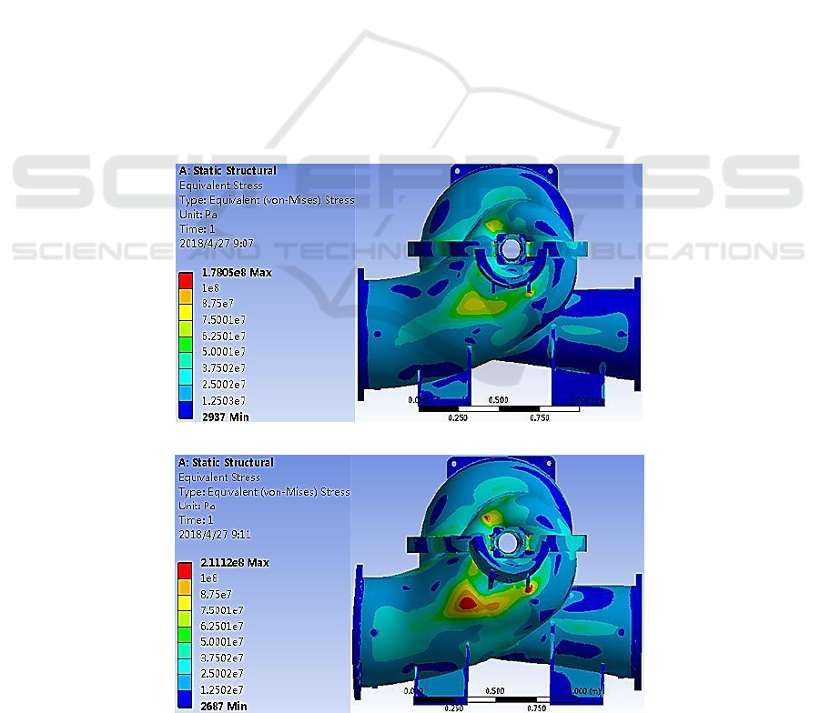
4.2. Applied Load and Result Analysis
The material of the shell is HT250. The Young's modulus is 1.38×
Pa, and the Poisson's ratio is
0.26. The ultimate stress is 250 MPa. The allowable stress [σ] for HT250 is 100 MPa. In the working
state, the shell is subject to its own gravity, the bottom constraint force and the fluid pressure of the
inner wall. When the wall thickness is 20mm, the equivalent stress distribution of the pump casing is
shown in Figure 8. According to the results, when the wall thickness is 20mm, the shell thickness
fully meets the requirements. Based on the above created parametric modeling method, when the
pump shell thickness is changed, the entire model will be automatically reconstructed based on the
function of size parameters and wall thickness. When the wall thickness is 16mm, the analysis results
are shown in Figure 9. It was found that a part of the stress in the suction chamber is greater than the
allowable stress of the material and does not meet the strength requirements. When the wall thickness
is less than 16mm, all the part strength no longer satisfied the requirement (as shown in Figure 10). In
actual working conditions, the pressure in the suction chamber is small [6], so the wall thickness of
16mm can meet the strength requirements. For this case, after numerical optimization, the total mass
with shell thickness 20mm is 1573kg, while for 16mm, the total mass is 1536kg, which saves a lot of
materials.
Figure 8. Equivalent stress distribution of 20mm wall thickness.
Figure 9. Equivalent stress distribution of 16mm wall thickness.
IWMCE 2018 - International Workshop on Materials, Chemistry and Engineering
248
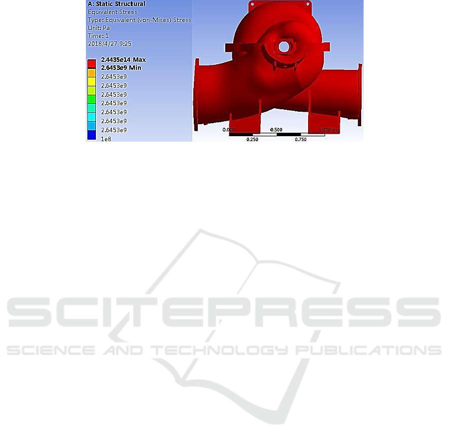
Figure 10. Equivalent stress distribution of 15mm wall thickness.
5. Conclusions
The three-dimensional model of the single-stage double-suction centrifugal pump housing is complex.
For the traditional modeling method, it is a very tedious task to modify the wall thickness. The
proposed method of parametric modeling in this work can easily and quickly modify the pump
housing thickness. The parametric drive model can be conveniently imported to Finite element
software to obtain the optimized wall thickness to meet the strength requirements, which also saves
materials, reduces designer's drawing work intensity, and improves the design accuracy and design
efficiency.
References
[1] Underwood C P, Royapoor M and Sturm B 2017 J. Parametric modelling of domestic air-
source heat pump Energy & Buildings 139: 578-589
[2] Zhang Z, Liu F, Wang P, Hu R and Sun B 2017 J. Methodology to parametric design of cam
profile for electronic unit pump Energy 139
[3] Peng B, Yang Y and Chun-Mo S U 2009 J. Parametric modeling of centrifugal impeller based
on solidworks api Journal of Engineering Graphics 30(5) 1-7
[4] Yu W P and Yu M 2015 J. Effect of Centrifugal Pumping Water Compartment Area on
Internal Flow Field Journal of Agricultural Equipment and Vehicles 53 (6) 25- 29
[5] Yao Z F, Wang F J, Xiao R F and et al 2012 J. Experimental research on pressure pulsation
characteristics of suction chamber and pressurized chamber of double suction centrifugal
pump Journal of Hydraulic Engineering 43 (4) 473- 479
[6] Su S Q, Liu X D and Li B X 2015 J. Optimum Design of Wall Thickness of Very Large
Autoclave Based on Pro / E and Workbench Mechanics Design and Manufacturing (5) 249-
252
Parametric Modeling of Single-stage Double-suction Centrifugal Pump Housing
249
