
Simulation of Temperature Field of Sponge Titanium
Prepared by Magnesium Thermal Reduction Process
N W Wang
*
and J X Zou
School of Vanadium and Titanium, Panzhihua University, 617000 Panzhihua,
People’s Republic of China
Corresponding author and e-mail: N W Wang, wnw_2008@163.com
Abstract. In this paper, based on the analysis of the current production process of titaniu m
sponge, the temperature field model was built by using the assumption of the model and the
temperature field of different models were simulated by using the FLUENT software. The
characteristics of temperature field was obtained in the process of sponge titanium prepared
by magnesiu m thermal reduction process under different process ways, by which a feasible
scheme was provided for the actual production.
1. Introduction
At present, sponge titanium production enterprises mainly produce titanium sponge by magnesium
thermal process (Kroll process). The main process is that sponge titanium is prepared by magnesium
reduction TiCl4, including reduction process and distillation process, and the reduction process is the
key link. The reaction of magnesium reduction to TiCl4 is a strong exothermic reaction. If the
residual heat in the reactor is not discharged in time, the temperature in the reactor will rise
sharply[1-5]. In this experiment, the temperature field is simulated in the reactor produced by Kroll
process using FLUENT software, the influence rule of process parameters are explored on the
temperature field distribution, and the direction of technological improvement is researched[6-8].
2. Establishment of model
2.1. Model assumes
The following conditions are assumed to hold for the process of the calculation.
(1) The liquid part in the reactor is a continuous medium, and the property parameters are consistent at
all parts.
(2) It is a complex process for magnesium reduction TiCl4. Not only can it obtain a single titanium,
but also it can generate three valence titanium and two valence titanium[9-10]. In order to simplify the
model, the reactor interior reduction reaction is referred to formula (1).
TiCl
4
+ 2Mg = Ti + 2MgCl
2
(1)
(3) TiCl4 added at the space above the liquid surface is completely vaporized. The reduction reaction
occurs only with the gas liquid reaction, and the reaction is evenly distributed across the surface on the
liquid. The reaction liquid is used as a reservoir in the reduction process.
392
Wang, N. and Zou, J.
Simulation of Temperature Field of Sponge Titanium Prepared by Magnesium Thermal Reduction Process.
In Proceedings of the International Workshop on Materials, Chemistry and Engineering (IWMCE 2018), pages 392-398
ISBN: 978-989-758-346-9
Copyright © 2018 by SCITEPRESS – Science and Technology Publications, Lda. All rights reserved

2.2. Mathematical equations
The energy equation is referred to formula (2) by using fluent software[11].
( ) ( E+ ) [ ( )]
t
eff
eff j j h
E v T h J v S
(2)
In the formula: t is time, s; Rho is density, kg/m
3
; E is energy, J; V is fluid velocity, m/s; P is
pressure, Pa; Lambda eff is the effective thermal conductivity coefficient, W/(m•K); T is temperature,
K; H
j
is the enthalpy of component j, j; the diffusion flux is j, mol/(m
2
•s), the effective viscous
dissipation coefficient, and the stress tension, Pa. The right side of the equation represents the energy
transfer caused by heat conduction, component diffusion and viscous dissipation. Sh contains the
chemical reaction (absorption) heat and other forms of defined volume heat sources. In this
experiment for cylindrical reactor, the axisymmetric physical parameters according to the center, so
can choose 2 d cylindrical coordinate to establish mathematical model of the reactor, the heat in the
form of differential equations can be written which referred to formula (3).
22
22
( ) ( )
h
t t t t t
c u v S
x y x y
(3)
In the formula: ρ is density, kg/m
3
; C is the specific heat capacity, J·kg/K; T is temperature, K; τ is
time, s; x and y are two directions of two dimensional space; U is moving in the x direction, m/s; V is
the velocity of the material in the y direction, m/s; λ is the thermal conductivity, W/(m•K),S
h
is the
heat source generated by the chemical reaction. In this paper, the position of the heat source is the
liquid surface, and its energy is characterized by the heat flux density generated by the chemical
reaction.
2.3. Basic physical parameters
In this experiment, the basic physical parameters of mixed liquid in the reactor are simplified[12].
Density and viscosity are calculated by simple rule of mixtures, this is shown in the following
formula (4).
11
;
nn
i i i i
ii
mm
(4)
In the formula: mi is the mass fraction of the liquid of each component, ρi is the density of
Components of the i, and ρ is the density of mixing liquid, kg /m3; Ui is the viscosity of component I,
u is the viscosity of the mixed liquid, Pa•s.
In the reduction reactor, the main component of liquid is the raw material of liquid magnesium,
magnesium chloride and titanium particles produced by the reduction reaction, under the condition of
high temperature, the thermal conductivity of magnesium chloride (5W/(m•K)) and the thermal
conductivity of the titanium particles(8W/(m•K) ) are obviously lower than the thermal conductivity
of the liquid magnesium(97.33W/(m•K)). Therefore, the thermal conductivity of liquid magnesium is
used to represent the thermal conductivity of the liquid in the reactor.
3. Setting of heat source
3.1. Heat dissipation mechanism
Reactor cooling is mainly through the wall of the gas convection and radiation heat dissipation of the
reaction exhaust[13]. Therefore, the unit wall heat dissipation unit time is the sum of convective heat
transfer and radiation heat transfer power, the relationship is referred to formula (5).
Simulation of Temperature Field of Sponge Titanium Prepared by Magnesium Thermal Reduction Process
393
44
q [( /100) ( /100) ] ( T )
w g w g
A T T UA T
(5)
In the formula: q is the sum of convection heat transfer power and radiation heat transfer
power, W; ε is the emissivity, W/(m
2
•K
4
) ; A is the heat dissipation area, m
2
; T
w
is the wall
temperature, K; T
g
is the air room temperature, K; U is the convection coefficient, W /
(m
2
•K).
3.2. Setting
Reduction process[14], the reactor heat mainly comes from magnesium reduction reaction
heat produced by the TiCl4, its main chemical reactions are gasification TiCl4 react with
magnesium liquid in the liquid level, main equation is referred to formula (6).
TiCl
4
+ 2Mg = Ti + 2MgCl
2
-519 kJ/mol (6)
Continuously for the reduction in the process of the reaction and assumes that the reaction
liquid level as the heat source location, depending on the feed rate, set different heat flux,
feeding rate of 260, 300, 350, 400 kg/h, set the heat flux density of 63 270 W/m
2
, 72 306
W/m
2
, 84357 W/m
2
, 96 408 W/m
2
.
4. Analysis and discuss
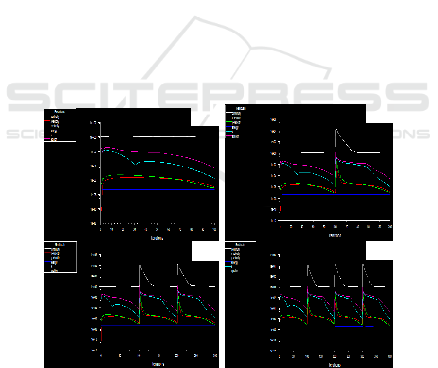
4.1. Iterative analysis
Analysis according to the requirement of feeding rate of 260 kg/h, 300 kg/h, 350 kg/h, 400 kg/h when
temperature field of iterative graph, as shown in figure 1.
Figure 1. Iterative diagram of temperature field at different feeding speeds.
(a) 260kg/h (b) 300kg/h (c)350kg/h (d) 400kg/h
(a)
(d)
(c)
(b)
IWMCE 2018 - International Workshop on Materials, Chemistry and Engineering
394
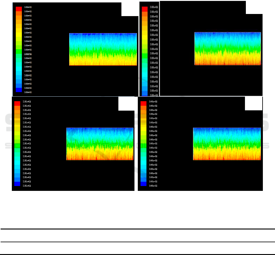
4.2. Analysis of temperature field in adiabatic condition
Assumption of all gasification of TiCl4, the distribution of temperature field in the reactor is shown
in figure 2, specific data are shown in Table 1. The simulation results are the distribution of
temperature field after the initial reaction of 1 h. From Table 4.1, with the increase of feed speed,
temperature rise in the post 1h reactor. When the feeding speed is 400 kg /h, the temperature in the
reactor is 100 degrees centigrade higher than the feed rate of 260 kg /h. It will be seen from this that,
if a long reaction will lead to a sharp increase in the temperature in the reactor, causing temperature
excursion. To control the temperature in the reactor, expelled heat from the reaction process, it is
necessary to heat the reactor.
Figure 2. Temperature distribution at different feeding speeds under adiabatic conditions.
(a) 260kg/h (b) 300kg/h (c)350kg/h (d) 400kg/h
Table 1. Central temperature corresponding to different feeding velocities under adiabatic
conditions.
feeding velocities /kg·h
-1
260
300
350
400
Central temperature /K
1200
1240
1280
1320
4.3. Analysis of the temperature field under natural air cooling condition
Through sampling the model, the physical parameters and setting of the boundary conditions. The
temperature field distribution in the designed reactor of 5.1 m × 1.8 m (reaction medium feed rate of
260 kg / h) was simulated. It can be seen from the simulation results that the reactor center
temperature is 1200K at the feeding rate of 260 kg/h, and the reactor wall temperature is about
(a)
(d)
(c)
(b)
Simulation of Temperature Field of Sponge Titanium Prepared by Magnesium Thermal Reduction Process
395
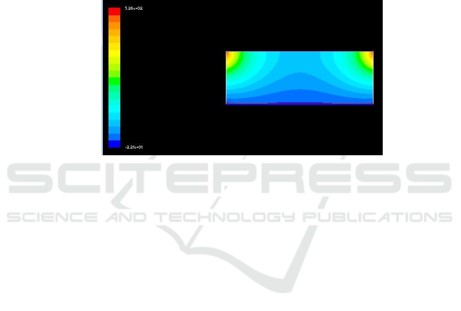
1020K, which is similar to the known temperature (1 010 ~ 1 039 K). As shown in Figure 3, it can be
seen that the model is feasible.
The model was used to simulate the distribution of temperature field inside the reactor, and under
different conditions of natural air cooling and different feed rates. It can be seen, with the increase of
feed rate, the center temperature and wall temperature showed an up, the wall temperature doesn’t
increase. However, as the feed rate increases, the temperature in the center of the reactor increases
from 1180K to 1300K. So increasing the feed rate, the center temperature rose sharply and it can
easily cause the reactor temperature over-temperature. In order to obtain better sponge titanium
quality and higher genuine rate, we need to increase the cooling capacity of the reactor. Generally
forced air cooling can be used.
Figure 3. Simulation results of temperature Field in reactor when feeding speed is 260kg /h.
4.4. Analysis of temperature Field under forced Air cooling
In the condition of forced air cooling, the temperature distribution of feeding velocity of 300 kg/h,
350kg /h and 400 kg/h is shown in figure 4, referred to Figure 4 (a), (b) and (c).
As can be seen from the graph, when the feeding speed has been increased, the temperature of the
reactor is close to the temperature field of which feeding speed is 260 kg/h and in the condition of
natural ventilation, and the temperature of the reactor decreases obviously.
It can be seen that forced air cooling has been used to dissipate heat which can effectively control
the temperature field in the reactor. Namely, the temperature of the reactor center is also close to the
temperature of low speed 260 kg/h when the feed rate of TiCl4 is significantly increased.
Simulation results of the temperature field in the reactor at different feeding speeds in forced air
cooling, referred to Figure 4.
In addition, related studies have shown that the relationship between feeding speeds and forced
air-cooled ventilation can be represented in the following form if the feeding speed is more than 260
kg/h, reference equation is listed by formula 7.
Y = 180 (X-260 ) +1570 (7)
In the equation, Y, ventilation,m
3
/h; X, feeding speed, kg/h.
By calculation, when the feeding speed is 260 kg/h, 300 kg/h, 350kg /h and 400 kg/h, the
ventilation is 1 570m
3
/h, 8 881m
3
/h, 17 876m
3
/h, 26 888m
3
/h respectively. With the increase of
feeding speed, the ventilation rate increases.
IWMCE 2018 - International Workshop on Materials, Chemistry and Engineering
396
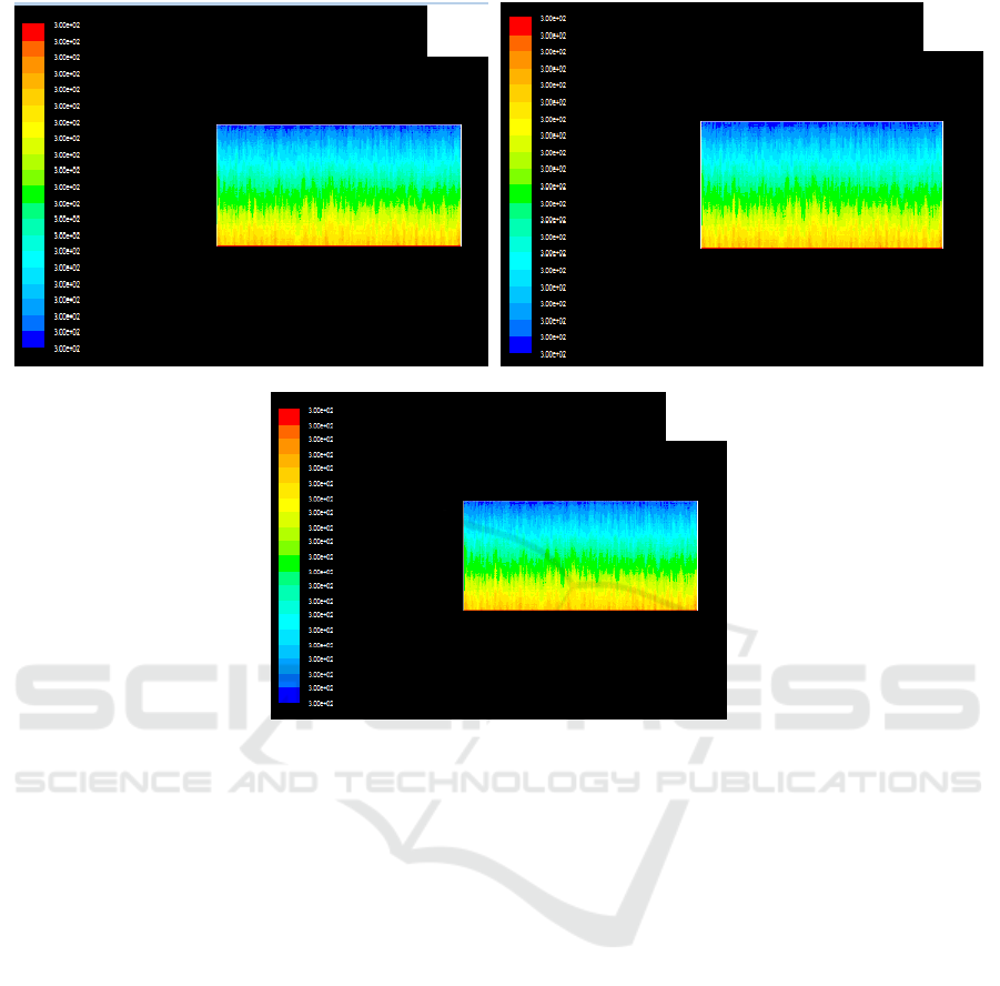
Figure 4. Simulation results of temperature field in reactor at different feeding speeds for forced air
cooling. (a) 300kg/h (b)350kg/h (c) 400kg/h.
Acknowledgements
This work is financially supported by Science and Technology Project of Panzhihua City. The title of
the project is Optimization of Thermal Reduction Process and Equipment for Sponge Titanium
magnesium, the project number is 2013CY-G-11.
5. Conclusions
(1) With the speed of feeding in raw material increases, the temperature of reactor
rises on condition that thermal is isolated. When the speed is 400kg/h, its central
temperature is 1320 K, and 260kg/h, 1200K. Compared to the temperature at
speed of 400kg/h, that at 260kg/h decreases by 120K.
(2) If the reactor is air cooling, its central temperature will rise with the speed of
feeding increases. When the speed is 260kg/h or 400kg/h, their respective
temperature is 1180K and 1300K. In contrast with the two speeds, the temperature
differs in 120K.
(3) Adding artificial winds, the temperature dispersion at speed of 300kg/h, 350kg/h,
400kg/h is similar with that at speed of 260kg/h and air cooling. When ventilation
quantity is 26888 m3/h and its categorical wind speed is as 17.2 times as air, the
speed of feeding TiCl4 can be increased to 400kg/h, and its central temperature is
907°C , the same as on condition that the speed is 260kg/h with air cooling.
(b)
(c)
(a)
Simulation of Temperature Field of Sponge Titanium Prepared by Magnesium Thermal Reduction Process
397

References
[1] Xie Y F 2009 Production technology and development direction of sponge Titanium M. China
Nonferrous Metals Industry Association,
[2] Li D C, Zhou D L and Liu H 2006 Magnesium Thermal Process Sponge titanium production
M. Metallurgical Industry Press
[3] Di W W, Liu Z H and Sun H M 2011 Analysis of heat transfer in titanium sponge production
process by MG reduction J. Titanium industry Progress Vol 28: p25-p29
[4] Dou S S, Wu F Z and Gao C T 2013 Study on forced heat dissipation of titanium sponge
reduction process by magnesium thermal method J. Nonferrous metals (smelting part)
Vol.6:p23-p25
[5] Li H B 2002 Effect of reducing feed on the structure of sponge titanium and improvement
measures J. Titanium industry Progress Vol.19: p39-p41
[6] Chen S P and Wen J N 2012 Computer simulation of the variation of the internal thermal field
of the titanium Sponge reactor J. Hunan Nonferrous Metals. Vol.1: p25-p26,p78
[7] Shen X X 2011 Status and development trend of titanium sponge production technology J.
Sichuan Metallurgical Vol.33: p1-p6
[8] Mo W, Deng G Z and Luo F C 2007 Titanium Metallurgy M.Metallurgical Industry Press
[9] Xiao Z Q and Zhu M Y 2006 Application of numerical simulation analysis technology
in metallurgical process M. Metallurgical Industry Press
[10] Wang X D 2009 Study on treatment of molten salt slag in sponge titanium production D.
Kunming: Kunming University of Technology
[11] Zhong W 2011 Numerical calculation method of chemical kinetics based on Arrhenius
theorem J. Chemical Studies Vol.22: p56-p60
[12] Wang Z C 2002 On the relationship between capacity and magnesium content of
titanium sponge single furnace J. Nonferrous metals (smelting part) Vol.3: p29-p30
[13] Ma X and Li B J 2014 Application of new heat insulating material in sponge titanium
and steam furnace J. Yunnan Metallurgy Vol.43: p86-p92
[14] Wu H D, Zhou X Z and Kang D C 2010 Study of the absorption - desorption of anode's
chlorine in magnesium electrolysis processing Light Metal. Vol.8:p53-p57
IWMCE 2018 - International Workshop on Materials, Chemistry and Engineering
398
