
The Microstructure Evolution and Wear Resistance of Laser
Cladding M2 High Speed Steel on Nodular Cast Iron
N J Xu
1,2
, C S Liu
1,3, *
, Z B Wang
1,3
and T Sun
1
1
School of Materials Science and Engineering, Northeastern University, Shenyang
110819, Liaoning, China
2
Key Laboratory for Anisotropy and Texture of Materials, Ministry of Education,
Shenyang 110004, Liaoning, China
3
Key Laboratory for Laser Application Technology and Equipment of Liaoning
Province, Anshan 114000, Liaoning, China
Corresponding author and e-mail: C S Liu, csliu@mail.neu.edu.cn
Abstract. M2 high speed steel (HSS) coating specimen was fabricated on nodular cast iron
by laser cladding (LC) using a solid state pulse Nd:YA G laser of wavelength 1064n m,
maximu m power of 400 W. Morphology, phase structure, micro -hardness and wear behaviour
of the specimens were examined by scanning electron microscopy (SEM) with energy
dispersive spectroscopy (EDS) analysis , X-ray d iffraction (XRD), Vickers indenter, friction
and wear tester measurement, respectively. Results show that the observed microstructure of
the cladded layer is characterized by equiaxed cellulars or dendrites and interdendritic
network shaped carbides. Martensite, retained austenite and MxCy type carbides are observed
in clad specimen. Average micro-hardness of clad specimen increases to 750HV and is 2.5
times as high as that of substrate. The increase attribute to the rapid solidification of HSSs,
and formation of finer grains. For dry sliding, the laser cladded M2 HSS layer shows the
better wear resistance in ambient.
1. Introduction
High speed steel (HSS) is a new kind of materials which could be used to make outlayer of rolls for
hot-rolling in steel making process. HSS rolls have strong capacity in terms of strip contour and have
been used for all working rolls of F1-F5 of 1580mm hot strip mill by many steel makers, such as
Baosteel. The quality of steel sheet, life of rolls and working efficiency are improved obviously by
applying HSS rolls. However, the surface degradation, such as wear and damage of rolls surface
frequently occurs because of severe service condition. Accordingly, it is necessary to find a way to
modify the original surface of roll, and to repair or remanufacture the worsen one [1].
Laser cladding (LC) of metals is mainly used to modify and repair the surface of various
mechanical parts, for increasing resistance to wear, erosion, corrosion and oxidation. And LC is also
particularly suitable to the treatment of small areas of machine parts, a capability that does not exist
with most other surface engineering techniques. The ability to treat localized zone and the versatility
of the treatment allow the surface properties of parts to be tailored precisely to service conditions.
Furthermore, large area coverage may be achieved by overlapping tracks, as a result of layer overlap
584
Xu, N., Liu, C., Wang, Z. and Sun, T.
The Microstructure Evolution and Wear Resistance of Laser Cladding M2 High Speed Steel on Nodular Cast Iron.
In Proceedings of the International Workshop on Materials, Chemistry and Engineering (IWMCE 2018), pages 584-590
ISBN: 978-989-758-346-9
Copyright © 2018 by SCITEPRESS – Science and Technology Publications, Lda. All rights reserved

during cladding, the clad material undergoes consecutive thermal cycles which could contribute to
progressive modification of its microstructure and properties [2].
Moreover, LC is now being a viable alternative to improve the quality of surface properties of
outlayer of rolls. There are considerable investigations on laser surface modification technique used
in HSS processing. Zhang et al. [3] reported that M2 HSS samples were fabricated by laser additive
manufacturing (LAM) and the microstructures of deposited samples were composed of
supersaturated martensite, retained austenite and M
2
C-type carbides. Wear resistances of all LAM
samples showed an adhesive wear mechanism, and M2 HSS had a lower friction coefficient and a
larger wear volume loss. Investigation of Liu and Leong [4] showed the microstructure
characteristics of M2 HSS parts produced by selective laser melting (LSM). The observed
microstructure from SEM and FIB was characterised by a continuous and homogeneous network of
dendrites within two different phases. The research results gave a thorough insights on the rapid
solidification phenomenon in SLM. Colaco et al. [5] showed that laser surface melting almost
completely eliminated the residual porosity and dissolved large brittle carbides that are present in the
as-sintered AISI M42 HSS samples, leading to an extremely fine and homogeneous microstructure.
Candel et al. [6] showed that AISI M2 tool steel coatings on medium carbon AISI 1045 steel
substrate have been manufactured and after Laser Cladding (LC) processing it has been applied a
tempering heat treatment to reduce the amount of retained austenite and to precipitate secondary
carbides. They found the microstructure is extremely fine and complex, with eutectic transformations
and MC, M2C and M6C precipitation. Therefore, after the laser coating is necessary to use post heat
treatments.
However, the above mentioned research is surface modification on conventionally fabricated HSS
steels and surface deposition on structure steels. To the best of our knowledge, there are many kinds
of material for core part of rolls used in steel making process. A preliminary investigation on
fabricating HSS on core materials of hot roll using LC technique is essential for promoting it to be
used in hot roll manufacturing. In the present study, LC treatment on nodular cast iron was carried to
investigate the effect of LC parameters. Microstructure, phases, and microhardness of all the LC
specimens were analyzed. Dry sliding wear were carried out on them and wear mechanisms were
studied.
2. Experimental procedure
Nominal chemical composition of gas atomized M2 HSS powder (−200/+325 mesh), manufactured
by AVIC Beijing Institute of aeronautical materials, is 0.996C- 6.32W- 5.03Mo- 3.93Cr- 1.78V-
0.193Mn- 0.312Si- 0.30Co- 0.330Ni- 0.252Cu- 0.020S- 0.031P (wt %). As-received nodular cast iron
substrate was cut into size of 20mm×15mm×10mm. Surface of the specimen was machined and
polished to remove the oxide scales, and then rinsed with acetone and deionized water.
LC treatment was performed using a 400W pulse Nd:YAG laser with a wavelength of 1064nm
(manufactured by Wuhan Tuanjie Laser Technology Co., LTD., Wuhan, Hubei, China). During the
treatment, a layer of powder with a controllable thickness between 20-100 μm was pre-placed. Argon
shielding gas was used during LC processing to avoid oxidation and contamination. A NUM 1060
CNC system was used to control the movement of a table to fabricate the desired specimen,
according to the sliced CAD data.
Extensive single-track laser cladding process was conducted to get optimized laser processing
parameters. Laser cladding conditions were laser power 18-44 W, scanning speed 2, 2.5 and 3 mm/s,
and beam diameter 0.32, 0.40 and 0.48 mm. Multi-track and multi-layer processing parameters were
as follows: laser power 23.5W, scanning speed 2.5mm/s, the amount of distance out of laser spot +14
mm, diameter of laser beam 0.48 mm, the thickness of coating 0.2 mm, and overlap ratio 50%.
After laser cladding treatment, specimens were sectioned, mounted, ground, polished and etched
with aqua regia. The cross-sectioned microstructure of the specimens were examined using an optical
The Microstructure Evolution and Wear Resistance of Laser Cladding M2 High Speed Steel on Nodular Cast Iron
585

microscopy (OM) and a scanning electron microscopy (SEM, JSM 7001F, JEOL, Japan) with energy
dispersive spectroscopy (EDS) analysis. The phases were identified by X-ray diffraction (XRD,
X’Pert Pro MPD-PW 3040/60, PANalytical, the Netherlands) with Cu Ka radiation generated at 40
kV and 40 mA, and the diffraction angle varied between 30
o
and 90
o
with a scanning speed of 1
deg/min. The micro-hardness of the cross section from the layer surface to the bulk was measured by
a Vickers indenter (401MVD, Wilson, USA) at room temperature under a load of 50 g and a dwell
time of 10 s. Wear resistance was performed on a friction and wear tester (MG200, Xuanhua
Mechanical Instrument Co. Ltd., China) in ambient air. Prior to wear testing, the specimens were
ground and polished with 1200 grit paper and rinsed with alcohol. A Cr12MoV steel with a diameter
of 6.0 mm was used as the counter-body. The parameters of the apparatus were set as an applied load
of 100 N, a fixed rotation speed of 250 rpm of the workbench, and a 30 min test time. Friction
coefficient was recorded. The wear weight loss was used to evaluate the wear resistance.
Microstructure of the worn surface was observed using SEM and the wear mechanism was analysed.
3. Results and discussion
3.1. Microstructure and EDS analysis
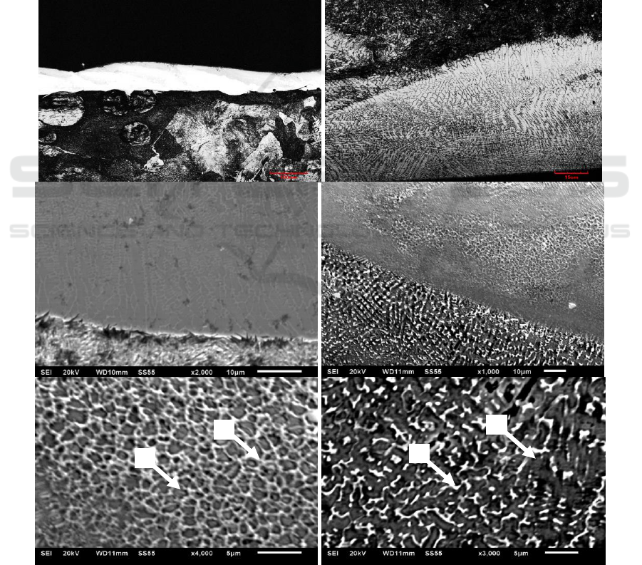
Figure 1 present the microstructure of laser cladded M2 HSS specimen. The surface obtained was
homogeneous and very refined, without relevant defects such as cracks and pores in the cross section
of clad (Figure 1(a)). Furthermore it is can be seen small amounts of cellular grains and large
amounts of dendrite grains with different growth orientation in Figure 1(b). As shown in Figure 1(c),
a metallurgical bond is formed between the clad and bulk with a typical bright zone. Figure 1(d)
shows the microstructure of overlapped zone. The grains at the middle of clad zone are coarser than
those in the edge of the clad zone. Moreover, the grain size was found to be finer at the second track
(Figure 1(e)) than that at the first clad track (Figure 1(f)).
As observed in Figure 1 (e, f) both zones experienced rapid solidification sufficient to suppress
the precipitation of bulk shape carbides resulting in a continuous and homogeneous network of
carbide dendrites within zones A, B, C and D. In addition, uniformity of the carbide dendrite network
is highly desired in M2 HSS because of resistance of dimensional and hardness changes by such kind
of morphology. During the LC process, the alloying elements have no time to diffuse as rapid
solidification. Under such a circumstance, the solid solubility is extended that would increase the
solid solution strengthening of LC parts. Secondly, the reduction in size and phase segregation was
observed from the continuous and homogeneous network of carbide dendrites. Grain size refinement
was also seen which would improve fracture and impact toughness of LC parts.
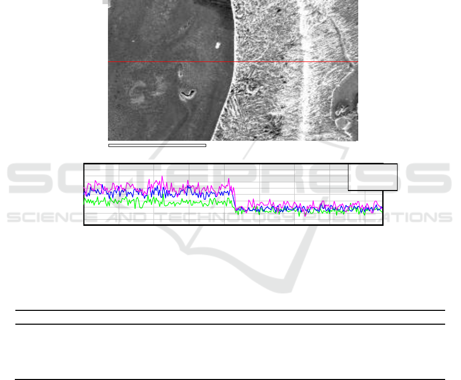
Figure 2 demonstrated the SEM morphology and EDS mappings of section across the interface
between the M2 HSS clad and nodular cast iron. It confirmed that the carbide forming elements such
as Mo, Cr and V are the main elements in the network-shape eutectic carbides (Figure 2(b)). Also it
is evidence that the distribution of Mo, Cr and V elements reveals the metallurgical bond as show in
Figure 2(a).
Table 1 EDS microanalysis confirmed that chemical composition of coating center area was not
close to M2 HSS powder initial composition. Alloying element micro-segregation was observed in
dendritic zone and network of carbide. Two distinct zones, A and B corresponding to zones marked
in Figure 1(e) could be a martensite in dendritic core, whereas interdendritic region where eutectic
transformation is present was rich in alloying elements as C, W, Mo, Cr and V. Another two distinct
zones, C and D corresponding to zones marked in Figure 1(f) were observed that carbon segregation
were similar and more severe than that of zone in Figure 1(e).
IWMCE 2018 - International Workshop on Materials, Chemistry and Engineering
586
3.2. X-ray diffraction analysis of phase structure
Figure 3 indicated that the main phase present in the laser clad M2 HSS samples consisted of bcc
phase, fcc austenite and MxCy-type carbides. It was difficult to detect the tetragonality of martensite
from the XRD pattern because of broadening of the diffracting peaks caused by finer grain size and
lattice strain, therefore, the bcc phase in rapidly solidified M2 HSS clad was assumed to be either
ferrite, martensite, or a combination of both, depending on the cooling rate during laser treatment [7].
A small amount of carbide was detected as the intensity of diffraction peaks MxCy-type carbide was
relatively weak, which suggests that the volume friction of carbide was less.
The combination of high alloy element contents in M2 HSS and non-equilibrium rapid
solidification condition provides the factors for the formation of eutectic reaction, ultimately forming
the network-shape eutectic carbides. Moreover, some alloy elements such as W, Mo, Cr, Vand C in
M2 dissolved into the matrix during austenitised at high temperatures. The elements could not be
precipitated from the matrix under the fast solidification, thus reducing the martensitic transformation
temperature point of Ms. Therefore, there was a small amount of residual austenite in M2 HSS at
room temperature [8].
Figure 1. Micrographs of laser clad M2 on nodular cast iron. (a) Cross section at low magnification,
(b) Region near the top, (c) Region near the bottom, (d) Interface between tracks, (e) Second track at
high magnification, (f) Firs track at high magnification.
Second clad track
First clad track
(e)
(f)
(c)
(d)
(a)
(b)
Cellular grain
White bright zone
Coarse grains
Fine grains
Overlap zone
Clad top
Heat effect zone
Nodular cast iron
Dendrite grain
Fine grains
B
A
C
D
The Microstructure Evolution and Wear Resistance of Laser Cladding M2 High Speed Steel on Nodular Cast Iron
587
3.3. Microhardness analysis
Microhardness on the laser clad surface are shown in Figure 4. The distribution of microhardness for
M2 clad was measured along its thickness perpendicular to the laser tracks. Initially, the M2 HSS
clad showed uniform microhardness along its thickness and its average microhardness was measured
to be 750 HV. All the hardness values for the laser clad surface were higher than those for bulk
nodular cast iron (300 HV). The increase of microhardness for the M2 HSS clad can be explained as
a result of the formation of finer grains of martensite and retained austenite with dense distribution of
very fine interdendritic carbides [9]. It also appears from the results in Figure 4 that the
microhardness of the M2 HSS clad is decreased starting from the transition zone toward the substrate
without sharply dropping.
IMG1
100 µm
Distance0.00 0.26 mm
Intensity0 200
Figure 2. The element distribution around interface between clad and nodular cast iron bulk (a) Red
line indicating the position on cross section; (b) Mo, Cr and V relative intensity along indicating line.
Table 1. Chemical composition of points by EDS (Mass%).
Point
C
W
Mo
Cr
V
Fe
A
5.85
3.07
2.02
2.04
0.80
85.01
B
6.95
4.08
3.07
2.35
0.95
81.67
C
8.21
1.50
0.93
0.84
0.33
86.61
D
12.50
0.75
0.69
0.68
0.27
83.40
3.4. Room temperature wear behaviour
The coefficient of friction (COF) of laser clad of M2 HSS and nodular cast iron under the
atmospheric condition was shown in Figure 5. The coefficient of friction of M2 clad showed a
fluctuant characteristic with the increasing of wear time, while for the nodular cast iron, the COF had
a trend of an initial increase followed by sharply increases with increasing wear times.
The wear test results were shown in the form of weight loss (Figure 6). The bulk surface showed
less wear resistance than the laser cladding surface. According to the samples under different wear
time, the wear weight loss was lowest for M2 HSS clad. Variation of the wear weight loss was not
Mo ——
Cr ——
V ——
(b)
IWMCE 2018 - International Workshop on Materials, Chemistry and Engineering
588
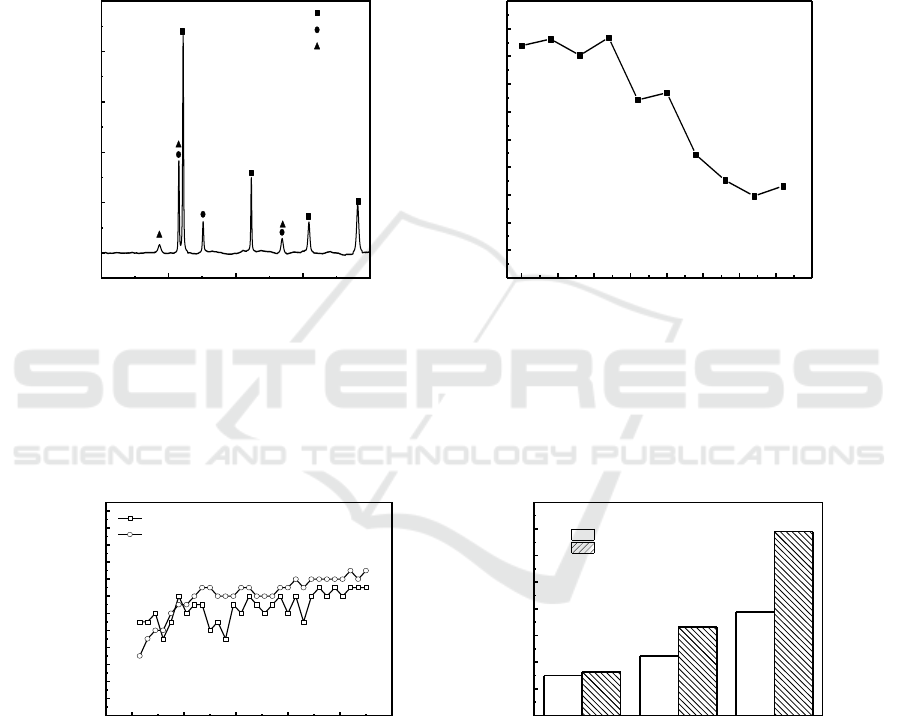
linear. When the samples were in wear time 30 min, the wear weight loss reached the maximum and
were the 56% weight loss of the bulk material.
Worn surfaces with dry sliding conditions of M2 HSS clad sample are given in Figure 7 which
revealed that the clad layer underwent less intense plastic deformation during the wear process. The
regular morphology of grooves along the direction of wear and small pits was detected, indicating
slight adhesive and abrasive wear. Besides, the worn morphology of M2 HSS clad sample in
different wear time 10, 20 and 30 minutes was similar and the scratches parallel to the sliding
direction were evident in every worn surface.
20 40 60 80 100
0
1000
2000
3000
4000
5000
a-Fe
g-Fe
M
x
C
y
Intensity / a.u.
2q / deg.
0.00 0.05 0.10 0.15 0.20 0.25 0.30 0.35 0.40
0
100
200
300
400
500
600
700
800
900
1000
Microhardness / HV0.1
Distance to the surface / mm
Figure 3. The XRD pattern of the laser clad M2
HSS specimen.
Figure 4. The microhardness with distance from
the surface of the laser clad specimen.
0 2000 4000 6000 8000 10000
0.10
0.12
0.14
0.16
0.18
0.20
0.22
0.24
0.26
0.28
0.30
0.32
0.34
Friction coefficient
Wear round / r
HSS M2 clad
Nodular cast iron
Figure 5. The wear coefficient of laser
clad M2 HSS and NCI specimen.
10 20 30
0.000
0.005
0.010
0.015
0.020
0.025
0.030
0.035
0.040
Wear loss / g
Time / min
HSS M2 Clad
Nodular cast iron
Figure 6. The weight loss of laser clad M2
HSS and NCI specimen.
The Microstructure Evolution and Wear Resistance of Laser Cladding M2 High Speed Steel on Nodular Cast Iron
589
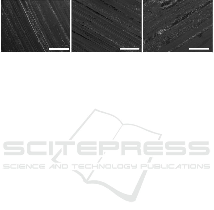
Figure7. SEM micrographs of the worn surface of the laser clad M2 layer under different
wear time (a) 10min, (b) 20min, (c) 30min.
4. Conclusions
Microstructure evolution of the M2 HSS cladded layer is characterized by equiaxed cellulars or
dendrites and interdendritic network shaped carbides. Martensite, retained austenite and MxCy type
carbides are observed in clad specimen.
Average micro-hardness of clad specimen increases to 750HV and is 2.5 times as high as that of
substrate. The increase attribute to the rapid solidification of HSSs, and formation of finer grains. For
dry sliding, the M2 HSS cladded layer shows the better wear resistance in ambient.
Acknowledgment
Financial support from the Fundamental Research Funds for the Central Universities of China (No.
N170207007) is acknowledged.
References
[1] Xu H B, Zhang J, Cao J G, Huang W M, Liao Q S and Zhang P W 2009 Application of HSS
roll in hot strip mill Mater Sci Forum 626-627 651-+
[2] Zhong M and Liu W 2010 Laser surface cladding: The state of the art and challenges
Proceedings of the Institution of Mechanical Engineers Part C: Journal of Mechanical
Engineering Science 224(5) 1041-1060
[3] Zhang M, Chen C, Qin L, Yan K, Cheng G, Jing H and Zou T 2017 Laser additive
manufacturing of M2 high-speed steel Materials Science and Technology 34 (1) 69-78
[4] Liu Z H, Zhang D Q, Chua C K and Leong K F 2013 Crystal structure analysis of M2 high
speed steel parts produced by selective laser melting Materials Characterization 84, 72-80
[5] Colaco R and Vilar R 1998 Effect of the processing parameters on the proportion of retained
austenite in laser surface melted tool steels J. Mater. Sci. Lett. 17 563–567
[6] Candel J J, Franconetti P and AmigóV 2013 Study of the solidification of M2 high speed steel
Laser Cladding coatings Revista de Metalurgia 49 (5) 369-377
[7] Niu H J and Chang I T H 2000 Microstructural evolution during laser cladding of M2 high-
speed steel Metall Mater Trans A 31 (10) 2615-2625
[8] Tuominen J, Näkki J, Pajukoski H, Hyvärinen L and Vuoristo P 2016 Microstructural and
abrasion wear characteristics of laser-clad tool steel coatings Surface Engineering 32 (12)
923-933
[9] Wang S H, Chen J Y and Xue L 2006 A study of the abrasive wear behaviour of laser-clad tool
steel coatings Surf. Coat. Technol. 200 3446–3458
(a)
(b)
500μm
500μm
(c)
500μm
IWMCE 2018 - International Workshop on Materials, Chemistry and Engineering
590
