
Failure Analysis of the Fluorine Rubber Sealing Ring Used in
Acidic Gas Fields
G Q Qi
1,2
, D T Qi
1,*
, H X Yan
2
, B Wei
1
, H B Li
1
, N Ding
1
, X D Shao
1
, D N
Zhang
1
and X H Cai
1
1
State Key Laboratory of Performance and Structural Safety for Petroleum Tubular
Goods and Equipment Materials, CNPC Tubular Goods Research Institute, Xi’an,
710077, China
2
School of Natural and Applied Science, Northwestern Polytechnical University,
Xi'an 710129, China
Corresponding author and e-mail: D T Qi, qidt@cnpc.com.cn
Abstract. The failure of fluorine rubber sealing ring occurs when it is used in the sulfur
condition after one year. By visual observation, there are some cracks and the color changed
to black from brown near the location of the contact delivery medium. In order to identify the
cause of the failure, the physical properties, structure and composition were tested and
compared with the same batch of the rings but without using.The results showed that the
hardness and density of the material were increased because of gas permeation. It is
evidenced by the microstructural observation, which shows that there are holes in the material
near the transport medium. The specimens were characterized by FT-IR and XPS,
respectively. The results show that the three-dimensional network structure of the ring is
destroyed and the peak strength of -CF
2
and -CF is weakened while the CH
3
, -CH
2
and –C=O
increase by the action of external stress and gas permeation. As a result of comprehensive
evaluation, the reason of sealing ring failure is fatigue aging during the long-termservice life.
The gas permeation leads to the destruction of the network structure, and accelerating the
aging process.
1. Introduction
The gas field contained hydrogen sulfide and carbon dioxide has become an important part of the
natural gas resources for exploitation in China nowadays[1,2]. Unfortunately, ordinary carbon steel
pipe corrosion is very serious in such high acidic environment. In recent years, the non-metallic pipe
with good corrosion resistance is researched and applied in the oil and gas field contained H
2
S or
CO
2
, and turned into an important direction for sulfur-containing conveying pipe, gradually[3].
During the oil and gas field exploitation, sealing ring is used in non-metallic pipe as an important
accessory[4]. Sealing performance and service life of rubber seal products are closely related to oil
and gas field environment, such as temperature, pressure, chemical corrosion, and et al. Furthermore,
with the increase of temperature and pressure in the pipeline increase and service environment
becomes worse. With the deepening of the exploitation depth and increasing severe environment, the
quality of rubber seal is put forward higher requirements and face enormous challenges. In the
Qi, G., Qi, D., Yan, H., Wei, B., li, H., Ding, N., Shao, X., Zhang, D. and Cai, X.
Failure Analysis of the Fluorine Rubber Sealing Ring Used in Acidic Gas Fields.
In Proceedings of the International Workshop on Mater ials, Chemistry and Engineering (IWMCE 2018), pages 651-657
ISBN: 978-989-758-346-9
Copyright © 2018 by SCITEPRESS – Science and Technology Publications, Lda. All rights reserved
651
process of transmission, due to the high temperature, high pressure and corrosive medium[5], the seal
products often failure caused by performance degradation, which lead to the contact stress release
between seal products and joints. In the service environment with H
2
S/CO
2
, accident such as
perforation or fracture often happened[6,7], usually results in oil and gas leak, even cause serious
accident, which may lead to huge economic losses, casualties and ecological damage.
It has a great significance that study on the corrosion damage behavior of sealing ring serviced in
corrosion environment, but there is few research report about this aspect. In this study, failure
analysis of fluorine rubber sealing ring used in non-metallic pipe which anti hydrogen sulfide is
investigated. For reliable operation and efficient design, the security of this engineering non-metallic
pipe especially, it is urgent to investigate the failure reasons of the sealing r ing and to further analyze
the factors which affect the pipeline’s serving ability. It will be of great benefit to prevent events
which could trigger disastrous incidents, thus can reduce much loses in terms of service life and
economics.
2. Material and methodologies
2.1. Background of the Failure
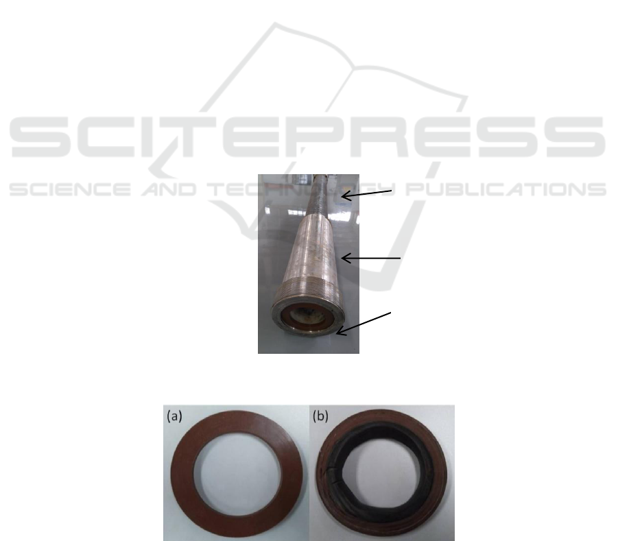
Non-metallic pipe (DN80 PN16MPa), as is shown in Figure 1, was used for oil gathering and
transportation in sour oil and gas field. The transmission medium is mostly gas, with a small amount
of oil and water. The pressure and temperature of transmission medium are 8.9MPa and 35 °C,
respectively. The content of H
2
S is 51800mg/m
3
while CO
2
of 3.80mol%. The whole construction
project had been completed on April 2015, while the pipeline had been started to use on May 2015.
After running for half a year, the inspection of pipeline application effect was carried out. The result
shows that the fluorine rubber sealing rings have failed with cracks and color changed shown in
Figure 2. Meanwhile, new sealing rings produced in the same batch were also collected for
comparison.
Figure 1. Structure of non-metallic pipe.
Figure 2. Macro morphology of (a) the new sealing ring and (b) used one.
non-metallic
pipe body
joint
sealing ring
IWMCE 2018 - International Workshop on Materials, Chemistry and Engineering
652

2.2. Failure description
It can be seen from Figure 2 that the color of the used sealing inside changes from brown to dark
obviously, while the outer color is not changed. Compared with the new one, the color changed
border of the used sealing ring is at a third place from inside to outside. Moreover, we can easily find
by visual observation that the color changed border have some cracks, also in the black area. We can
also find that it has an obvious squeeze traces in the sealing ring surface, and the thickness decreases
from 7.72mm to 6.54mm, approximately.
2.3. Methodologies
Many factors may cause the failure of sealing ring and more studies are needed. Firstly, the
background information and the operation conditions that might lead to failures of the ring were
investigated in detail. Secondly, probable causes for failure of ring were systematically analyzed by
various measurements, such as Shore hardness, density, morphology observations, composition
analysis, etc.
The specimens of sealing ring were cut from the same failed one which was taken from the
pipeline after running for half a year. By comparison, specimens for above tests were also taken from
a new ring which produced from the same batch with the failed one. At least three specimens taken
along the circumference of the ring were tested for each measurement to evaluate the results
statistically. The "used" samples were collected from the area close to the damage region of the failed
ring (as seen in Figure 2b). The "new" samples were taken from the new ring (as seen in Figure 2a).
Surface morphologies of rings were detected bydigital microscope (KH-7700, Hirox, Japan)and
scanning electron microscope (SEM, JEOL-6700F, Tokyo, Japan). To check any significant chemical
modification of the fiber, the specimens were characterized by Fourier transform infrared
spectroscopy (FT-IR) and X-ray photoelectron spectroscopy (XPS), respectively, which were
obtained by using a Nicolet Avator 360 Spectrometer (Wisconsin, USA) and a PHI5300 X-ray
photoelectron spectrometer (PE Corp., USA).
3. Results and analysis
Analysis contain morphology and structure will be conducted as follows to study the actual reason
for such gradual failure of the sealing ring.
3.1. Analysis of physical properties
Firstly, the physical properties of the new sealing ring and used one were investigated, can be seen in
table 1, the Shore hardness value of the used sealing ring are increasing compared to the new one’s
(the value of Shore hardness is 27.6). For the old sealing ring, of particular note is Shore hardness
value of the black part is bigger than the brown part’s. That is to say, the part of the sealing ring to be
exposed to fluid change to harden gradually.
Table 1. the physical properties of the new sealing ring and used one.
Types
Shore Hardness
Density (g/cm
3
)
The new ring
27.6
2.1296
The brown part of the old one
29.2
1.8391
The black part of the old one
33.6
1.7539
The density of old sealing ring is smaller than the new one, and the black part of the sealing ring
even smaller than the brown part. The reason due to the density decline after the sealing ring used in
acidic gas fields together with the non-mental pipe is corrosion medium, such as H
2
S, CO
2
, permeate
into the body of sealing ring, and then the pores become more and more bigger with the service time
Failure Analysis of the Fluorine Rubber Sealing Ring Used in Acidic Gas Fields
653
increasing. The pressure difference between inside and outside of the pipe lead to the occurrence of
gas permeation.
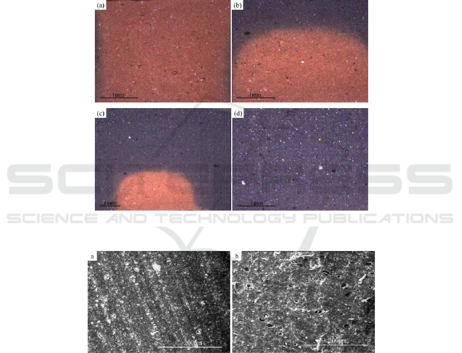
3.2. Analysis of microstructure
For researching the microstructure of the invalid sealing ring, the optical microscope was used to
characterize the structure. From the Figure 3, we can find that the color of the sealing ring used for
half year changed from brown to black partially and obviously.
For further research, scanning electron microscope was used to characterize the microstructure.
There are some micrometer grade pore in the used sealing ring(seen in Figure 4 b) , compared to the
new one (seen in Figure 4 a). The arising pores are resulted from gas permeation.
Figure 3. Optical microscope of the sealing ring used for half year.
Figure 4. SEM of the sealing ring (a) the new one; (b) the used one.
3.3. FT-IR analysis
Due to service in acidic gas fields, the sealing ring, along with the time increasing, with some aging,
which have the characteristics of the physical properties deterioration, some cracks and color change.
For understanding what have changed for compositions of the sealing ring with aging, The structures
of the sealing ring were characterized by Fourier transform infrared spectroscopy. Figure 5 compares
the FT-IR spectrum of the used sealing ring with the spectra of new one. The peaks at around 884
cm
-1
, 2852 cm
-1
and 2922 cm
-1
are assigned to =CH, -CH
2
and –CH
3
vibration, respectively, bending
stretching. The absorption peaks at 1742cm-1 is due to –C=O stretching. Moreover, -CF and -CF
2
IWMCE 2018 - International Workshop on Materials, Chemistry and Engineering
654
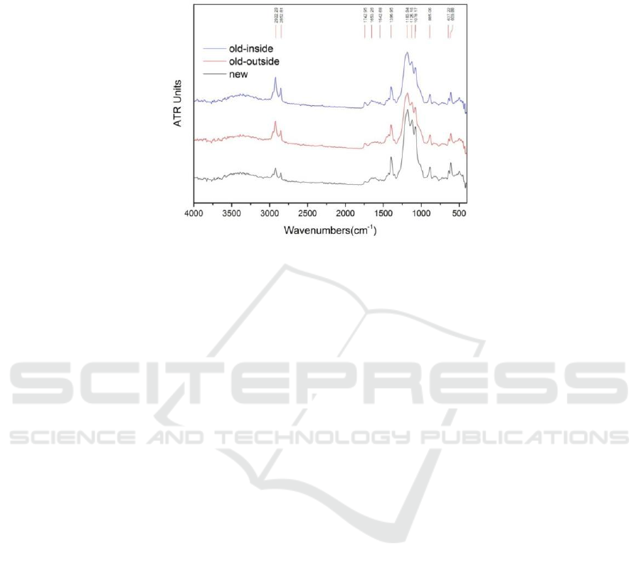
bending stretching at 1078 cm
-1
, 1125 cm
-1
, and 1181 cm
-1
respectively, reveals the existence of
fluorine in the sealing ring.
Figure 5. FTIR of sealing ring.
Through the tests (Figure 5), the results show that the old ring absorption peak is close to the new
one, but the absorption intensity is different. It can be seen from Figure 5 that the absorption intensity
of -CF and -CF
2
decreases while the absorption intensities of CH, CH
2
, CH
3
and C=O increase with
the service life of the fluorine rubber seal ring increasing. During the aging of the sealing ring, the
position of the unsaturated bond in the rubber molecule is oxygenated to C=O structure. On the
contrary, -CF and -CF
2
bond strength decreased, indicating that -CF and -CF
2
bond breakage and
recombination, which lead to the degree of branching increase, eventually. That is the reasons why
the -CH group absorption intensity increase. Therefore, the cause of failure of fluorine rubber seals is
due to molecular breakage and cross linking.
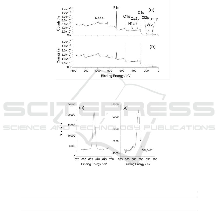
3.4. XPS analysis
Elemental ID and Quantification of the new and the used sealing ring are shown in Figure 6. It is
seen obviously that the element exist in the rubber mainly include Si, S, O, C and F. The trace
additives such as Na, Ca, Cl and N not be investigated in this study. By comparing the elemental
quantification of two rings (in table 2), the content of O and C element increase, with the percent
content of atomic (at. %) from 13.82 to 19.25, 59.91 to 64.94, respectively. Contrarily, the content of
F element decrease with the percent content of atomic from 14.34 to 7.11, the elemental F peak of
both used and new rings counts to binding energy relation is shown in Figure 7.
4. Discussion
In the actual process of service, the sealing ring need to withstand a certain compressive stress, even
more alternating pressure. In this case, the aging of the sealing material is directly affected by the
stress. In addition, the aging of the seal ring is also affected by the results of the rubber material,
components and contact with the external environment (such as temperature, H
2
S and CO
2
and other
transmission medium). From the pressure gauge reading for pipe connecting, the ring by the value of
compressive stress at sealing ring reach 24MPa. The macroscopic analysis of the fracture
morphology shows that the occurrence of the crack due to the compressive stress is too large, and
then the molecular chain of rubber is cut off by stress (Figure 5). However, the latter part of the study
found that, there is not appear similar phenomenon in the air environment when applied stress at
24MPa. Through mechanical analysis, the reason is that partial molecules of the transmission with
the service time increases, will be permeated into the inside of the rubber and make volume
Failure Analysis of the Fluorine Rubber Sealing Ring Used in Acidic Gas Fields
655
expansion. Furthermore, rubber network structure of the molecular chain will expand to three-
dimensional space. The excessive deformation will cause loss of elasticity, reduce the rubber material
resilience, and result in decreased sealing performance, eventually. The applied stress and gas
permeation promote each other, and accelerating the aging of the sealing ring[8-10].The reason of the
color of theused sealing inside changed from brown to black is that the rubber chemical additives
react chemically with H
2
S and CO
2
which from transmission.
Figure 6. XPS analysis of (a) used sealing ring and (b) new one.
Figure 7. F1s scan in (a) the used sealing ring and (b) the new one.
Table 2. Elemental Quantification of the new sealing ring (At. %).
sample
O
F
C
New sealing ring
13.82
14.34
59.91
used sealing ring
19.25
7.11
64.94
For the fluorine rubber aging process, it can be divided into three stages[11,12]. Firstly, the rubber
make an elastic deformation after loading, also known as softening. Secondly, as the stress or
deformation is relatively slow and cannot be evenly distributed, it will focus and generate rupture
nucleus somewhere, in the rubber surface or internal. Thirdly, the rupture nucleus increases until the
rubber is destroyed as a whole.
Therefore, according to the analysis the structure, composition and related physical properties of
the failure of the seal, comparison with the same batch of non-service sealing ring, it is shown that
IWMCE 2018 - International Workshop on Materials, Chemistry and Engineering
656

the failure of the used sealing ring is due to fatigue aging. During the process of service life, the
sealing ring structure change and properties degradation due to the applied stress, and the gas
permeation accelerates the fatigue aging process.
5. Conclusions
1) The reason of sealing ring failure is fatigue aging during the long-term service life.
2) The gas permeation leads to the destruction of the network structure, and accelerating the aging
process.
3) This type of sealing ring is not suitable for using in acidic gas fields, high-grade sealing
materials should be selected. for preventing the sealing ring failure used in theacidic gas fields, the
most important strategies is evaluations and detections before using.
Acknowledgement
The project was supported by the National Natural Science Foundation of China (Grant No.
51304236).
References
[1] Li H B, Y M L, Qi D T, Ding N, Cai X H, Zhang S H, Li Q, Zhang X M and Deng J L 2012
Failure analysis of steel wire reinforced thermoplastics composite pipe J. Engineering
Failure Analysis 20 88-96
[2] Qi D T, Yan M L, Ding N, Cai X H, Li H B and Zhang S H 2010 The 7th international MERL
Oilfield Engineering with Polymers Conference, London, UK
[3] Bai Y, Xu F and Cheng P 2012 Investigation on the Mechanical Properties of the Reinforced
Thermoplastic Pipe (RTP) Under Internal Pressure [C]. The Twenty-second International
Offshore and Polar Engineering Conference, June 17-22, Rhodes, Greece: International
Society of Offshore and Polar Engineers
[4] Drake K and Callaway R 2014 New polymeric materials development for extreme
environments [C]. OTC-25304, Offshore Technology Conference, Houston, 5-8
[5] Yamabe J and Nishimura S 2013 Failure behavior of rubber O-ring under cyclic exposure to
high-pressure hydrogen gas J. Engineering Failure Analysis 5 193-205
[6] Stevenson A 1983 A fracture mechanics study of the fatigue of rubber in compression Int. J.
Fracture 23 47-59
[7] Mars W V 2002 Cracking energy density as a predictor of fatigue life under multiaxial
conditions J. Rubber Chemistry and Technology 7 5 1-17
[8] Ayoub G, Naït-Abdelaziz M, Zaïri F, Gloaguen J M and Charrier P 2012 Fatigue life
prediction of rubber-like materials under multiaxial loading using a continuum damage
mechanics approach: effects of two-blocks loading and R ratio J. Mechanics of materials
52 87-102
[9] Le S V, Marco Y, Calloch S, Doudard S and Charrier P 2010 An energetic criterion for the
fatigue of rubbers: an approach based on a heat build-up protocol and μ-tomography
measurements J. Procedia engineering 2 949-958
[10] Poisson J L, Lacroix F, Méo S, Berton G and Ranganathan N 2011 Biaxial fatigue behavior of
a polychloroprene rubber Int. Jour. Of Fat. 3 1151-1157
[11] Bathias C, Legorju C, Chuming L, Menabeuf L 1996 Fatigue crack growth damage in
elastomeric materials[C]. In: Elastomeric materials ASTM. STP 505-13
[12] Cruanes C, Berton G, Lacroix F, Méo S and Ranganathan N 2014 Study of the fatigue
behavior of the chloroprene rubber for uniaxial tests with infrared method J. Elastomery 18
3-9
Failure Analysis of the Fluorine Rubber Sealing Ring Used in Acidic Gas Fields
657
