
Numerical Simulation on Welding
R
esidual Stress and its Effects on
Loading Behavior of Extended Arm Structure
Ang Ji
1
, Minggang Chen
2
, Liping Zhang
3
, Binbin Zhang
2
and Le Gao
1
1
XCMG Research Institute Co., Ltd,Xu Zhou, China
2
XCMG Fire-fighting Safety Equipment Co., Ltd, Xu Zhou, China
3
State Key Laboratory of Intelligent Manufacturing of Advanced Construction Machinery, Xu Zhou, China
Keywords: Extended arm structure, welding residual stress(WRS), numerical simulation, welding deformation, loading
behaviour.
Abstract: In this article, the numerical simulation method was utilized to investigate the welding deformation and
residual stress of the extended arm structure. Then the distortion and stress distribution of extended arm
structure under loading state were calculated with and without considering the welding residual
stress(WRS). The results show that the welding residual stress around weld toe is very high and the
maximum Von Mises stress in weld zone is up to 550MPa, which is more than 3 times higher than that of
middle area. When welding situation is taken into consideration, the Von Mises stress around the weld area
reaches the yield strength of base metal while the Von Mises stress apart from the weld area decreases on
account of the offset by WRS. The welding deformation is the main part of the structural deformation in X
and Z direction under welding&static situation and the deformation in Y direction is 38.28mm, which is the
stack of welding deformation and down warping with static load.
1 INTRODUCTION
Residual stresses are self-equilibrating stresses that
are present within a structure when no external
forces are applied[1-3]. Typically, kinds of material
processing and fabrication techniques create a
residual stress in workpiece. One of the most
common and high residual stress is caused by
conventional welding process near the welding
region in metallic structures, where extremely
uneven plastic deformation, temperature change and
phase transformation in different degree occur[4].
During the serving process, the actual stress is very
complicated based on the stack of WRS and working
stress, which is bound to have a certain effect on the
loading behavior and fracture resistance[5].
Many scholars have studied the WRS and its
influence on the bearing capacity of the structure. Li
Yanjun et al.[6] analyzed the influence of WRS on
the load bearing capacity of the container y-shaped
ring joint by using the finite element analysis
method. The results showed that the axial tension
stress was obviously enlarged by the combined
action of WRS and internal pressure and the
maximum stress of the Y-ring under loading also
enlarged a little. Xiao Qi[7] set the air cylinder as
research object and analyzed the influence of WRS
on the result of air cylinder structure strength
calculation, finding that the existence of WRS could
lead to the change of weak link location of structural
strength in cylinder body and the bearing capacity
decreased obviously.
XuLei[8] investigated the influence of WRS in
welding zone of spherical shell on the ultimate
bearing strength and come to a conclusion that WRS
played little or no role in the ultimate bearing
strength which provided certain reference on the
post weld stress relief treatment. Takeshi
MIYASHITA[9] researched the load-carrying
capacity of joint between I shaped girder and thick
plate by stress free method and the test results
confirmed that the slope of stress distribution in the
plate thickness direction increases as the thickness of
the plate increases and the residual stress in the thick
plate does not affect the load-carrying capacity for
the bending of steel girders.
The extended arm is a commonly used welding
structure in the field of engineering machinery, and
its bearing capacity is directly related to the
construction and safety performance of the whole
machine[10]. During the static load calculation of
the general preliminary structure design, the
designer mainly ensure the safety by expanding the
safety factor, and there is no specific analysis on the
influence of residual stress on the structure loading
behavior. Therefore, based on the extended arm as
the research object, the influence of WRS on the
loading behavior is analyzed through the finite
element simulation method so as to provide certain
reference for the design of whole structure and
welding process.
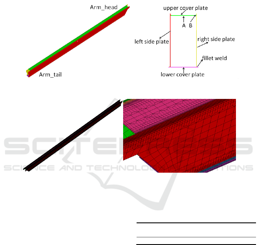
Fig.1 The geometrical model and section form of the extended arm.
Fig.2 Grid model of extended arm structure.
2 PHYSICAL MODEL OF
EXTENDED ARM STRUCTURE
The extended arm structure is set as the research
object of welding and structure finite element
analysis in this article. The WRS and its influence
on loading behavior is the main investigation
contents, hence the finite element model only
includes the upper and lower cover plate, left and
right side plate as well as fillet welds. The
geometrical model and section form of the extended
arm are shown in Fig.1.
The material used for extended arm is Q550 and
the carbon dioxide gas shielded welding method is
utilized for four fillet joints with the welding power
Fronius TPS5000. There is no groove on the plate
and the weld shall be cleaned before welding. The
welding process parameters are shown in Table 1.
Table.1 Welding process parameters.
Name Current I/A Voltage U/V
Velocity
V/
(
mm·s
-1
)
Value 170~180 19~20 9
3 FINITE ELEMENT ANALYSIS
MODEL OF EXTENDED ARM
3.1 Generation of Extended Arm Grid
Model
The geometrical model of extended arm is
partitioned into solid grid model with 8 nodal
hexahedral element[11]. The base mental is divided
into 2~3 layers in order to ensure the accuracy of
calculation and the size of grid around weld and
HAZ is controlled at 2mm so as to improve the
calculation speed, while the size of grid remote from
welding zone is 12mm. Two element transitions are
adopted in the width direction among the above-
mentioned regions to ensure the accuracy of
calculation and reduce the number of elements. As
shown in Fig.2, the element number of grid model is
344294.
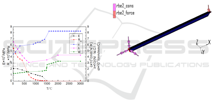
3.2 Material Property Parameters
Q550 is a typical high strength structural steel used
in engineering machinery field. It is assumed that the
whole model has the same thermal physical property
parameters with the change of temperature. The base
metal and welding wire are set to have isotropic
properties: poisson's ratio is 0.33, mass density is
7870 kg/m3, and the other parameters such as
thermal conductivity, specific heat, elastic modulus,
thermal expansion coefficient with the temperature
change are shown in Fig.3.
Fig.3 The relationship between heat-force parameters and
temperature of Q550.
3.3 Boundary Conditions and Loads
In the process of establishing the welding finite
element model, the Goldark double ellipsoid heat
source is selected as the boundary condition of the
welding heat source[12]. Since there is a temperature
difference between the workpiece surface and the
surrounding environment during the actual welding
process, the Newton's law and boltzmann's law are
taken into consideration respectively in the process
setting of the convection and radiation dissipation
between workpiece and external environment[13].
In the model calculation of welding process, the
solid-state phase transformation and work hardening
of low carbon steel are ignored for the reason that
both of them have little influence on welding
residual stress and deformation. The extended arm is
in a free state during the welding process, and the
mechanical boundary conditions are set to prevent
the rigid body displacement of the model.
In the static analysis of the extended arm, the
condition that the extended arm is in the horizontal
state and the load in the arm head is 2000N is taken
into consideration in this paper. As shown in Fig.4,
the element of the arm head is connected by RBE2
unit and the load in Y direction is set as 2000N. In
actual situation, the main constraint boundary
conditions at the end of arm are contact constraints
with the follow arms, which is most accurate.
However, owing to the influence of WRS on the
loading behavior of the extended arm is mainly
discussed in this calculation, the other RBE2 rigid
connection is added to impose a direct displacement
constraints at the end of the extended arm.
Fig.4 Boundary condition of extended arm static analysis.
4 COMPARISON AND ANALYSIS
4.1 Analysis of Welding Deformation
and Residual Stress
Based on the above-mentioned welding boundary
conditions, the model is set and the welding load is
solved. After the calculation is completed, the
welding deformation and welding residual stress of
the extended arm are extracted. The welding
deformation contours in X, Y and Z direction are
shown in Fig.5, from which some results can be
achieved that the extended arm is mainly contracted
in X direction and the total shrinkage is 6.12mm,
while In Y direction, the extended arm is down
warped and the downward deflection is 1.15mm.
The main reason for above distortion is that the
welding seams of the upper cover plate and the
lower cover plate are on the different planes and the
distance between two weld seams on the upper cover
plate is less than that on the lower cover plate. The
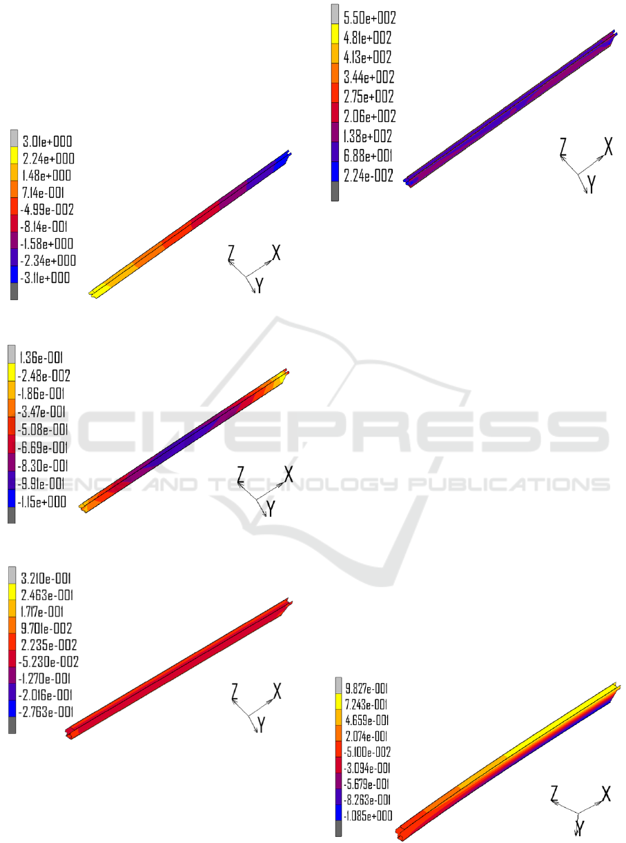
deformation of extended arm in Z direction is
mainly the contraction deformation along the section
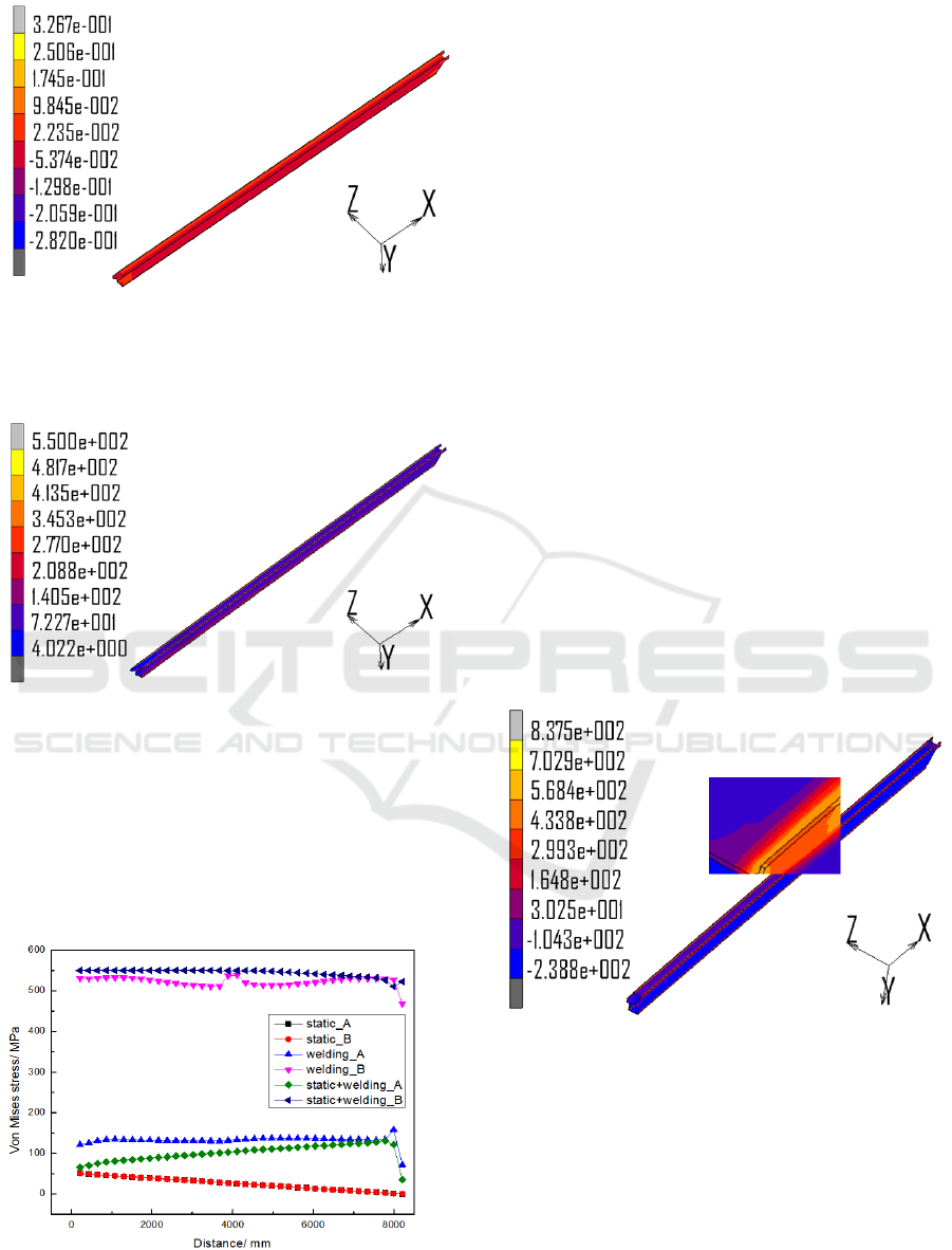
direction and the amount is very small. Fig.6 shows
the VONMISES stress contour of extended arm
structure. It can be seen that the largest equivalent
stress occurred in the weld region and the largest
equivalent stress is up to 550 MPa which has
reached the yield strength of base metal.
(a) Welding deformation contour in X direction
(b) Welding deformation contour in Y direction
(c) Welding deformation contour in Y direction
Fig.5 Welding deformation contour of extended arm
structure.
Fig.6 The Von Mises stress contour of extended arm
structure.
4.2 Structure Analysis Without
Considering the Welding Residual
Stress
Based on the above-mentioned static analysis
boundary conditions, the model is set and solved.
After the calculation is completed, the deformation
and working stress of the extended arm are
extracted. As the load is applied in the Y direction,
the main focus is on the displacement of the
extended arm in Y direction. Fig.7 shows the
displacement distribution of extended arm in Y
direction, as can be seen, the maximum structural
deformation of the extended arm occurs in the
position of the arm head, and the deformation
amount is 36.19mm. The maximum deformation of
the upper cover plate in X direction is 0.98mm,
while the maximum deformation of the lower cover
plate in X is -1.09mm. The deformation of extended
arm in Z direction is smaller and negligible since the
effect of side load is not considered. Fig. 8 shows
the overall Von Mises stress contour of the extended
arm structure. As can be seen from the figure that
the maximum Mises stress with its value being
114Mpa is located in the restrained position of the
extended arm.
(a) Displacement distribution contour in X direction
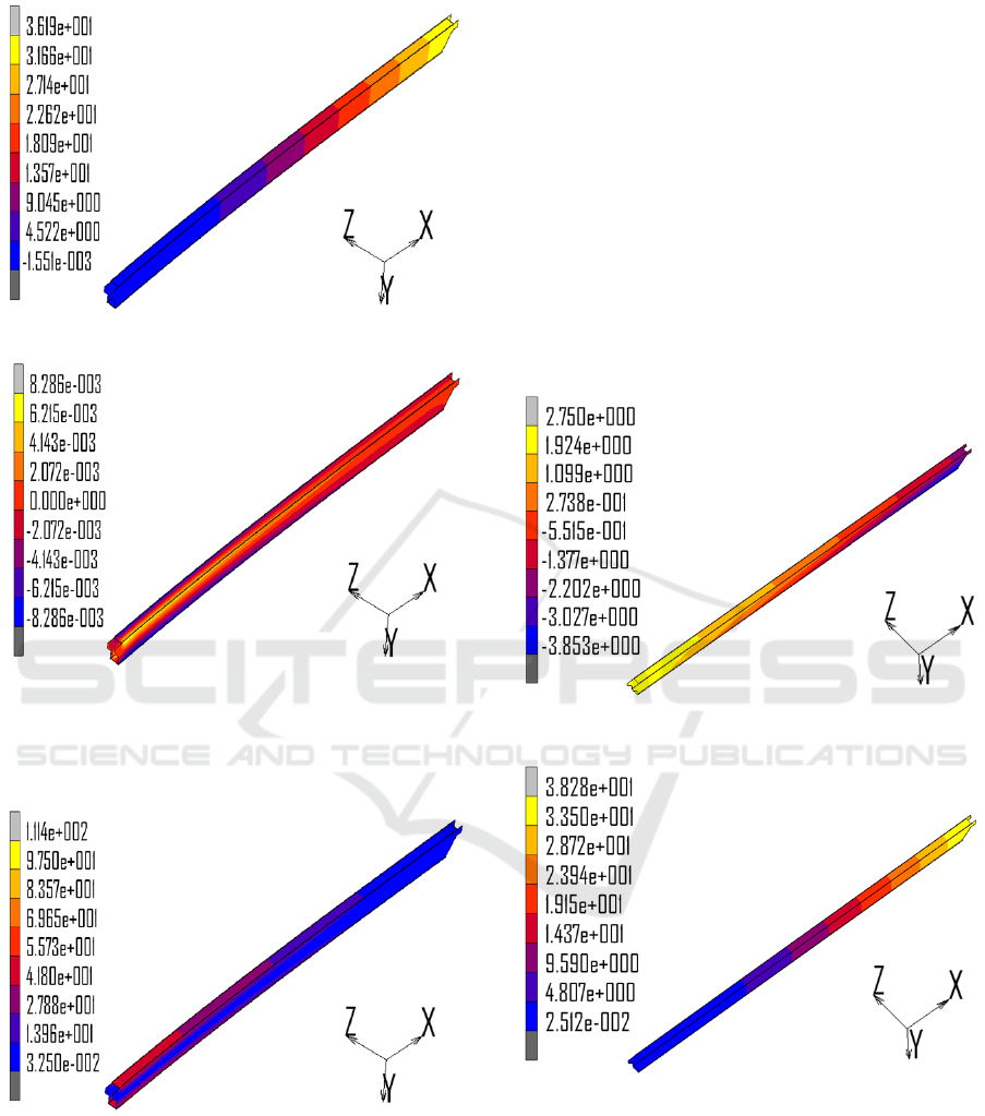
(b) Displacement distribution contour in Y direction
(c) Displacement distribution contour in Z direction
Fig.7 Displacement distribution contour of extended arm
structure.
Fig.8 Von Mises stress distribution of extended arm
structure.
4.3 Structural Static Analysis
Considering the Welding Residual
Stress
Based on the above-mentioned welding and static
analysis boundary conditions, the model is set and
solved. After the calculation is completed, the
deformation and working stress of the extended arm
are extracted. The displacement distribution
contours of extended arm in X, Y and Z direction are
shown in Fig.9, from which some results can be
achieved that the deformation of the extended arm is
still mainly in the Y direction, the largest welding
deformation occurs in the position of arm head, and
the deformation amount is 38.28mm. Besides, the
extended arm is contracted in X direction and the
total shrinkage is 6.6mm. Fig.10 shows the Von
Mises stress contour of whole extended arm
structure. It can be seen that the largest Mises stress
occurred in the weld region and the largest
equivalent stress is up to 550 MPa which has
reached the yield strength of base metal.
(a) Displacement distribution contour in X direction
(b) Displacement distribution contour in Y direction
(c) Displacement distribution contour in Z direction
Fig.9 Displacement distribution contour of extended arm
structure
Fig.10 Von Mises stress distribution of extended arm
structure
4.4 Comparison and Analysis
In order to compare the stress distribution under
different conditions(welding, welding&static, static),
the stress distribution data along the length direction
in position A and B shown in Fig.1 are extracted.
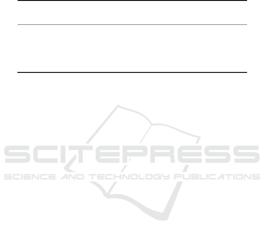
The stress distribution is shown in Fig.11.
Fig.11 Comparison of Von Mises stress under different
conditions.
As can be seen from the diagram, the Von Mises
stress in position B is much higher than that in
position A and the average Von Mises stress around
weld toe is more than 3 times higher than that of
middle area. The reason for the high value of stress
in position B is that the welding toe is located at the
junction of fusion zone and base metal where the
gradient of temperature change is large and the
plastic deformation is very uneven. The Von Mises
stress curves of two positions are basically
coincident under static conditions, the main reason
for this phenomenon is the bending moment of both
positions are almost identical owing to the same
distance to the centroid of extended arm structure.
With the increase of the length of extended arm, the
bending moment caused by the external force
decreases gradually, resulting in the decrease of Von
Mises stress of position A and position B gradually.
The Von Mises stress in position B is still much
higher than that in position A under welding&static
conditions, which has little difference from the value
in welding condition. The main stress in position B
mainly comes from the welding residual stress. In
addition, the Von Mises stress in position A is
smaller than the WRS in welding condition, the
reason for decrease is that the stress in X direction
caused by welding as shown in Fig.12 is pressure
stress which can be offset by the tensile stress in
static condition.
Fig.12 Welding residual stress of extended arm in X
direction.
Tab.2 shows the comparison of extended arm
deformation in different conditions, from which can
we find that the deformation in X direction in
welding&static condition mainly results from the
welding deformation. The deformation in Z direction
in welding&static condition mainly comes from the
welding deformation as well. The deformation value
in Y direction is 36.19 mm under load in static
condition, while the value comes to 38.28 mm in
welding&static condition which mainly results from
the stack of welding deformation and downwarping
with static load.
Tab.2 Comparison of extended arm deformation in different conditions.
X
min
/m
m
X
max
/m
m
Y
min
/
mm
Y
max
/m
m
Z
min
/
mm
Z
max
/
mm
Welding -3.11 3.01 -1.15 0.14 -0.28 0.32
Static -1.08 0.98 0 36.19 -0.01 0.01
Welding&stat
ic
-3.85 2.75 0.03 38.28 -0.28 0.33
5 CONCLUSIONS
(1) The welding deformation and residual stress
of the extended arm structure is investigated in the
numerical simulation method. The results show that
the welding residual stress around weld toe is very
high and the maximum Mises stress in weld zone is
up to 550MPa, which is more than 3 times higher
than that of middle area.
(2) The Von Mises stress around the weld zone
in welding&static condition is up to 550 MPa, which
is mainly influenced by the welding residual stress,
while the stress apart from the weld area decreases
on account of the offset by the WRS.
(3) The welding deformation is the main part of
the structural deformation in X and Z direction
under welding&static condition and the deformation
in Y direction is 38.28mm, which is the
superposition of welding deformation and
downwarping with static load.
REFERENCES
1. Flores-Johnson E A, Muránsky O, Hamelin C J, et al.
Numerical analysis of the effect of weld-induced
residual stress and plastic damage on the ballistic
performance of welded steel plate[J]. Computational
Materials Science, 2012, 58:131-139.
2. Nikkarila J P, Manninen M. Introduction to the
characterization of residual stress by neutron
diffraction /[M]. Taylor & Francis, 2005.
3. Lammi C J, Lados D A. Effects of residual stresses on
fatigue crack growth behavior of structural materials:
Analytical corrections[J]. International Journal of
Fatigue, 2011, 33(7):858-867.
4. Cheng Xiaoyu, Wang Xiaomei. The essence and
adjustment of residual stress[J]. Total corrosion
control, 2009, 23(7):33-35.
5. GaoZhanyuan, GuoYanlin.Analysis on Influence of
welding residual stress on ultimate bearing capacity of
Y-joints[J]. Journal of architectual science and
engineering, 2016, 33(6):73-80.
6. Li Yanjun, Wu Aiping, Liu Debo, et al. Numerical
simulation on Y-ring welding residual stress and its
effects on loading behavior of propellant
tank[J].Transactions of nonferrous metals society of
china, 2017, 27(4):701-707.
7. Xiao Qi. Study on numerical method of strength
analysis based on coupling method of welding residual
stress and service load[D]. Beijing Jiaotong
University, 2014.
8. Xu Lei, Huang Xiaoping, Wang Fang. Effect of
welding residual stress on the ultimate strength of
spherical pressure hull [J]. Journal of ship mechanics,
2017, 21(7):864-872.
9. Miyashita T, Inaba N, Hirayama S, et al. Measurement
method for welding residual stress in steel I-shaped
girder with thick flange and its influence on load
carrying capacity for bending[J]. Structural
Engineering, 2015, 3:191-208.
10. Liu Min. Structure analysis and optimization of
autocrane [D]. Chang an university, 2014.
11. Wang Changli. Numerical simulation of welding
temperature distribution and stress variation
[D].Shenyang University of Technology,2005.
12. John Goldak,AdityaChakravarti,Malcolm Bibby.
A new finite element model for welding heat
sources[J].Metallurgical Transactions B,1984(15)
:299-305.
13. Deng D. Theoretical prediction of welding distortion
in thin curved structure during assembly considering
gap and misalignment [D]. Doctoral Thesis, Osaka
University, 2002.
