
Research in the Processes for Manufacturing Matrix-body Curved-
profile PDC Bits Using the Method of Fusion and Penetration
Yuwen Xiong
1
,Tonghong Li
2
and Quanxin Liu
1
1. Mechanical Engineering Department, Ezhou Polytechnic, Ezhou, Hubei, China
2. Hubei Province Diamond Tool Testing Center, Ezhou, Hubei, China
Keywords: Matrix-body; Curved-profile bit; PDC; fusion and penetration (impregnation).
Abstract: As integration of the modern 3D printing technology with the traditional mold manufacturing technology, the
method of fusion and penetration is used to produce the matrix-body curved-profile PDC bits. This method
includes mainly such processes as the prototype 3D printing, mold copying, mold and material loading,
fusion and penetration, and after-treatment. This method is capable of effectively using a variety of
materials of special properties at different locations of the bit to ensure it has a reasonable structure and high
dimensional accuracy hence ideal application effect, The manufacturing processes are simple with both
manufacturing quality and manufacturing efficiency improved.
1 INTRODUCTION
Polycrystalline Diamond Compact (“PDC”) bits are
a kind of drilling tools commonly applied in the
geological industry. Main examples are geological
exploration, coalfield drilling (for example, anchor-
rod-type PDC bits, and three-wing PDC bits), and
oilfield exploration. Among them, the PDC bits used
for oilfield exploration are the most expensive and
satisfy the most stringent requirements. They can be
called “the noble” among PDC bits. A PDC bit
consists mainly of the bit body, cutters, nozzles, bit-
body outer-wall wear-resistance reinforcement layer,
and the joint. Traditional PDC bits have a steel body
made of nickel-chromium-molybdenum alloy.
Firstly, the alloy stock is machined into the initial bit
body. Then the initial bit body is heat treated. After
the heat treatment, holes are drilled in the bit body.
And man-made PDC cutters are pressed or welded
to the crown of the bit body. Finally, the tungsten
carbide bars are affixed to the bit-body outer wall for
purpose of wear-resistance enhancement. The steel
body is notorious for low wear and fracture
resistance. Thus the high wear resistance of the PDC
cutters is compromised, with the drilling efficiency
reduced and the repair or replacement interval
shortened. Matrix-body PDC bits as a new type of
PDC bits use different materials from those used in
traditional PDC bits. They have a matrix body that
is made of WC/W2C other than nickel-chromium-
molybdenum alloy. Benefits of the matrix-body
PDC bits include high wear resistance and drilling
efficiency. Using the pressureless impregnation
technology, bronze as binder is applied into the
structure the skeleton of which is formed by
tungsten carbide powder. The matrix body is hence
formed. Then, by brazing, PDC cutters are affixed to
the crown of the matrix body. Natural diamond bars
are attached to the outer wall of the matrix body for
purpose of wear-resistance enhancement. The matrix
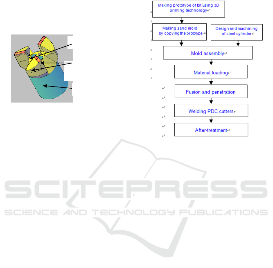
body is shown in Figure 1. Recent years have seen a
great change in both quality and variety of matrix-
body PDC bits. For example, engineers have
optimized the interface between tungsten carbide
matrix and PDC cutters. Furthermore, important
breakthrough has also been made in the design and
arrangement of PDC cutters, with their toughness,
abrasion resistance, and thermal stability improved a
lot. Nowadays, adoption of new-type smart
manufacturing technology makes also a huge
contribution to the improvement of the quality of
matrix-body PDC bits. These bits possess much
greater resistance to erosion and impact. In this
paper, the modern 3D printing technology and the
traditional mold manufacturing technology are
combined to put forth new processes for making
matrix-body curved-profile PDC bits. Intention is to
overcome the difficulty in machining the crowns that
are made of super hard materials and have a quite
complex shape. These processes make mass
production of the bits possible. These bits hence can
be more effectively applied in more industrial fields.
Figure 1 Schematic of matrix-body curved-profile PDC
bit.
2 PROCESSES FOR MAKING
MATRIX-BODY CURVED-
PROFILE PDC BITS
Generally, curved-profile PDC bits have a complex-
shaped crown. Two to four cutting wings protrude
from the head platform. Three to five PDC cutters
are welded to each cutting wing. Gates are prepared
in the areas between the cutting wings. Cooling
water circulates through these gates while drilling.
The entire crown has a curved profile. It is more
difficult to manufacture the curved-profile PDC bits.
On the one hand, it is more difficult to control the
machining accuracy of the curved surfaces; on the
other hand, the matrix body is made of the hard
materials WC/W2C. Once the curved surfaces are
formed, it is difficult to machine them. Furthermore,
formation of the cutting wings must ensure the
required dimensional and shape accuracy, and the
gates and the locations for welding the PDC cutters
must be formed during the formation of matrix body.
Taking into consideration the structural and material
characteristics of the bits, the technology of fusion
and penetration (pressureless impregnation) is an
effective solution to the mentioned difficulties.
Figure 2 shows the flow chart of the technology.
Figure 2 Process flow for making the matrix-body
curved-profile PDC bits using the method of fusion and
penetration .
2.1 Making Silica Gel Prototype of Bit
Using 3D Printing Technology
The primary task for the manufacturing of matrix-
body curved-profile PDC bits is to make the silica
gel prototype using the modern 3D printing
technology. First, the 3D solid model of the bit is
built with the design software (for example, PRO/E,
UG, CAD, or SolidWorks). With the model
modified and analytically optimized, the STL file is
directly outputted. Sectioning is then performed.
Next, the 3D printing (fused deposition modeling
(FDM)) is directly performed to produce the silica
gel prototype. The 3D printing technology applies
the “dispersion/accumulation” principle for gradual
formation. The designers can directly view the
model design, and perform the CAE simulation and
analysis using the simulation software. This is good
for communication, optimization and improvement.
The prototype can be made at the specified speed
and accuracy. The whole process is both flexible and
controllable, removing the need of any tooling. The
steps from design to modeling can be completed
with a dozen of hours. ABS, wax, and nylon
filaments are available for the FDM technique. The
modeling temperature is anywhere from 80 to
120ºC, and the modeling accuracy can be 0.1mm. In
addition, the after-treatment is simple, the cost is
low, and the material utilization rate is as high as
100%. When making the silica gel prototype, Mei
PDC cutter
recombination片
WC matrix body
(Fusion and
penetration of bronze
particles)
Steel
cylinder
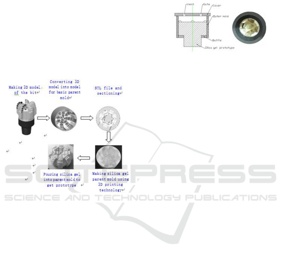
Xiaoqin[1] adopted a method which additionally
incorporated the process for intermediate model
conversion. First, she built the 3D model of the bit
using the software PRO/E, and converted the 3D
model into the model of basic parent mold. Then she
got rapidly the basic parent mold using the FDM
technique. Finally, she poured silica gel into the
basic parent mold to get the prototype of the bit. The
process flow of this method is shown in Figure 3.
Advantages of this method are effectively
implementing the bit structural design, and ensuring
the quality of basic parent mold. Disadvantages of
this method are adverse influence on manufacturing
efficiency and manufacturing cost.
Figure 3 Conversion from model to mold .
2.2 Making Sand Mold By Copying 3D
Printed Mold
The silica gel prototype is used for making the clay
mold or the sand mold. WC powder is placed in the
clay mold or the sand mold, then they undergo the
fusion and penetration process in an electric furnace.
The matrix body is thereby obtained. Generally, the
clay mold is made with the pouring method. Diao
Wenqing[2] made the Φ96 matrix body of the PDC
bit with the pouring method. First, he performed the
design, calculation and machining of the graphite
mold casing, and fixed the silica gel prototype. For a
sufficiently long time, he mixed steadily a proper
amount of clay powder with water according to a
certain mixing ratio to get the slurry. Then he poured
the slurry into the assembly, thus the cavity between
the mold casing and the silica gel prototype was full
of slurry. Within half an hour since the completion
of the pouring process, the slurry solidified to gain
certain strength due to reaction between the clay and
the water. He took out the silica gel prototype, to get
the clay mold as shown in Figure 4. Finally, the clay
mold was dried. This mode was to be used in the
fusion and penetration process of matrix body.
Figure 4 Making the clay mold .
The sand mold may also be used in the process of
fusion and penetration of matrix body. Difference in
respect of manufacturing process exists between the
sand mold and the clay mold. The silica gel
prototype is placed in the graphite mold casing.
Then the mixture of emery grit, resin adhesive and
curing agent is put in the assembly, to fill the cavity.
Wait approximately 2 hours for the sand mold
solidification. Then directly take the silica gel
prototype out of the assembly. The sand is quartz
sand with a 200 mesh in grain size, to ensure the
matrix body resulting from fusion and penetration
has an ideal roughness. The resin adhesive is furan
resin or phenolic resin. The mixing ratio of emery
grit, resin adhesive and curing agent is 100:1.2:0.6.
The sand mold can be made faster and more simply.
2.3 Machining of Steel Cylinder
The steel cylinder is the basic component of the bit.
One end of the steel cylinder is tapered, and
machined to have shallow rippled grooves, so that
the WC matrix body can be consolidated with
bronze in the process of fusion and penetration. The
consolidation result is acceptable. The other end of
the steel cylinder is machined to have female
threads, for connection with the drill rod. In case the
bit is worn, it can be easily replaced with a new one.
The steel cylinder is often made of #45 steel. In
addition to machining, it undergoes also the heat
treatment process. Both the outer diameter and the
inner diameter of the steel cylinder must be in
accordance with those of the bit. Inward and
outward taped surfaces are arranged where the
matrix body is connected to the steel cylinder. To
ensure the shape and taper of the outward tapered
surfaces, a steel sleeve with a tapered mouth is
machined along with the steel cylinder. The steel
sleeve will be used in making the clay mold or the
sand mold. See Figure 5.
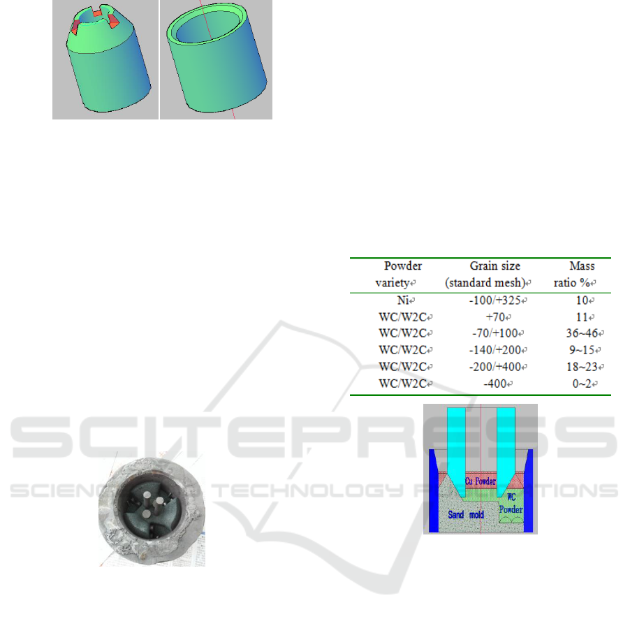
Figure 5 Combination of steel cylinder and steel sleeve.
2.4 Assembly of Mold and Mold Casing
Fix the steel cylinder at the center of the assembly of
mold casing and clay mold/sand mold. Gates (i.e.
preformed graphite bars) are attached with quick-
action adhesive to the locations in the bit for the
gates. To the locations for the PDC cutters in the
clay mold/sand mold, graphite chips are stuck,
which have the same shape and dimensions as the
PDC cutters. These graphite chips are prepared in
advance, and will be removed with the completion
of the matrix body manufacturing, to make room for
the PDC cutters to be welded. To the inner wall of
the mold casing, polycrystalline diamond bars are
stuck. Through the process of fusion and
penetration, these bars will be affixed to the surface
of the matrix body, serving to enhance wear
resistance. See Figure 6.
Figure 6 Assembly of mold and mold casing.
2.5 Material Loading
Materials used for the matrix body are mainly WC
or W2C powder, as well as a small amount of
metallic materials added for property modification.
Referring to table 1, the WC/W2C powder must use
a multi-grain-size formula, to ensure the ideal
overall compactness and surface quality of matrix
body from the process of fusion and penetration. A
frequency- adjustable vibrator shall be used for
powder loading. The vibrator keeps vibrating the
mold casing and the mold, so that the powder flows
substantially into the cavity between them.
Generally, a small amount of WC/W2C powder is
first loaded, to a depth of about 5mm from the end
of the steel cylinder. Then more WC/W2C powder is
added until the level reaches the bottoms of the
cutting wings. Finally, copper-based or ferrous
metal-based powder is added to the tapered surfaces
at the roots of the cutting wings. The powder serves
as connection. The subsequent turning process in a
lathe is feasible for these tapered surfaces. See
Figure 7. With the powder loading process
completed, a certain amount of bronze particles and
borax are placed in the clearance between the
uppermost mold casing wall and the steel cylinder.
Then the assembly can be transferred into the
furnace to receive the process of fusion and
penetration.
Table 1 Mass ratios of materials used in matrix body.
Figure 7 Loading powder in the assembly.
2.6 Fusion and Penetration
The matrix body of the curved-profile PDC bit
adopts the technology of fusion and penetration
(impregnation). The technology is in the field of
powder metallurgy. The whole assembly is heated in
the furnace. The heating scheme shall meet the
specification. The first stage is heating to
somewhere from 1000ºC to 1100ºC; the second
stage is temperature holding. All bronze particles
melt, penetrating into the voids of the WC/W2C
powder skeleton. Result is a compact matrix body.
Generally, the heating at the early stage shall be
controlled at a slow rate. First, it is good for reliably
warming the mold casing and the clay mold or sand
mold. Secondly, it is good for slowly volatilizing the
resin adhesive and curing agent off the assembly. Be
sure to prevent the assembly deformation due to

rapid heating rate. The entire process of fusion and
penetration takes approximately five minutes, with
all the bronze particles penetrating the voids of
WC/W2C powder skeleton, and the steel cylinder
integrated with the matrix body.
2.7 PDC Cutters Brazing
With the matrix body obtained from the process of
fusion and penetration, PDC cutters welding is
performed to get eventually the PDC bits. First,
remove the graphite chips, and clean the locations
for welding the PDC bits. These locations shall have
no oil stain or oxidation scales. Then, using the
copper-based or silver-based welding agent, and the
high frequency heating process, weld the PDC
cutters to these locations. Equipment used for
making PDC cutters is a six-acting-face high-
temperature, high-pressure press. Usually, the PDC
cutters have a regular shape, cube, prism, or
cylinder. The welding agent is of copper-based,
silver-based, aluminum-based, or nickel-based alloy,
with a melting point above 450ºC. With the welding
in progress, the fluxing agent is added, such as
borax, boric acid, chloride, or fluoride. The high-
frequency electric induction heating/welding yields a
good many benefits, such as simple operation, being
free of local deformation, high welding strength,
considerable material saving, and excellent
mechanical behaviors.
2.8 After-treatment
The after-treatment processes mainly refer to the
machining of the tapered surfaces of ferrous metal-
based powder from fusion and penetration, and the
finishing of the edges, corners, and surfaces. In
addition, the parts temporarily used for the
formation of the gates must be removed. Machining
methods include turning, drilling, milling, and sand
blasting.
3 CONCLUSIONS
The technology of fusion and penetration used for
making the matrix-body PDC bits consists mainly of
such processes as making the prototype using the 3D
printing technology, making the clay mold or sand
mold by copying the 3D printed mold, material
loading, fusion and penetration, and after-treatment.
As integration of the modern 3D printing technology
and the conventional mold manufacturing
technology, the method of fusion and penetration is
capable of effectively applying a variety of materials
of special properties at different locations on the bit,
to form a gradient mechanical properties system.
Moreover, this method is capable of ensuring the
required structural and dimensional accuracy of
PDC bits. The products are notable for fairly good
application results. Their manufacturing processes
are simple, with the manufacturing quality and
manufacturing efficiency enhanced.
REFERENCES
1. Mei Xiaoqin, Yin Guofu, Xu Jin et al. Technology for
rapid formation of the basic parent mold for matrix-
body PDC bits based on the FDM technology [J].
Drilling Technique, 2012.35(2):57-59.
2. Diao Wenqing, Tang Dayong. Research in the
sintering process of matrix-body PDC bits used in
oriented drilling [J]. Coal Science and Technology,
2013,41(3):21-23.
