
Numerical Analysis and Experimental Research of Autofrettaged
Shrink-fitted Three-layer Extrusion Cylinder
Gexia Yuan
1
, Juanping Wang
1
, Feizhou Li
1
and Baoyan Zhang
1
1
School of Mechanical Engineering, Baoji University of Arts and Sciences, No.44, Baoguang Road, Shaanxi Baoji, China
Keywords: Three-layer extrusion cylinder, Shrink-fit, Autofrettage, Residual stress, Strength, ANSYS
Abstract: Multilayer cylinder is a commonly used structure of ultra-high extrusion cylinder. In order to increase the
load carrying capacity and durability of a shrink-fit three-layer extrusion cylinder, the paper proposed the
multiple autofrettage process based on analysis of simulation. Firstly, A 3-D finite element contact model of
the extrusion cylinder has been constructed in the ANSYS environment; The element used here is 3D
SOLID 186, and using a bilinear isotropic hardening model approximating the real material behaviour.
Then, we have used the model to simulate processes of fitting, autofrettage and boring of extrusion cylinder
by multi-step load and birth and death element techniques, then comes to the residual stresses of different
times autofrettaged cylinder. The results show multiple-autofrettage can increase hoop compressive residual
stress. The extrusion cylinder was made three times autofrettage processes and boring machining, its actual
elastic operating pressure is consistent with finite element analysis results and it’s strength is improved
significantly.
1 INTRODUCTION
Hydrostatic extrusion technology is a new type of
material processing method, and it can extrude the
materials, which are difficult to use conventional
deformation process to machining, such as
hydrostatic extruding tungsten alloy materials, etc,
their strong toughness can be greatly improved[1-4].
Hydrostatic extrusion pressure of high strength
material as high as 1000 MPa to 1500 MPa, so the
design of extrusion cylinder strength is particularly
important [2, 3]. If the design is careless, the bore
area will cause plastic deformation even burst. For
example, in a research institute, the pressure of a
three-layer shrink-fit extrusion cylinder(TSEC) was
designed to be 1500MPa, according to the theory of
maximum tensile stress theory, however, when
extrusion pressure had not reached 1500MPa, the
bore area of the cylinder appeared plastic
deformation, which leading to squeeze rod difficult
to move and hard to be sealed, until it didn’t work.
Ultra-high pressure extrusion cylinder mostly is
adopted multi-layer cylinder structure, and strength
design used elastic failure criterion. AA Miraje, SA
Patil[5, 6] and Shildip D Urade [7] had researched
the residual stress distribution through the cylinder
thickness of multi-layer shrink-fit cylinder(MSC)
based on the theory of maximum tensile stress
theory; Yuan Gexia et al.[8] had researched
optimization design of MSC based on the theory of
the maximum shear stress theory using analytical
method and finite element method. Yuan Gexia and
Liu hongzhao[9,10] had researched residual stress of
shrink-fitted and autofrettaged double cylinder.
Cylinder is usually made of plastic material, and it is
in the three direction stress state, so designing
strength according to the maximum shear stress
theory is more close to actual value.
In this paper, according to the actual tensile
compressive stress-strain curve of material, using a
bilinear isotropic hardening model approximating
the real material behaviour, and applying 3D SOLID
186 element, We have constructed a 3-D finite
element contact model for the extrusion cylinder in
the ANSYS environment to simulate processes of
shrink-fitting, autofrettage and boring of the
extrusion cylinder. The simulation results show that
Multiple-autofrettage processes can effectively
generate favorable compressive residual stresses to
increase strength of shrink-fitted cylinder. Then,
three times autofrettage process and boring
machining to the extrusion cylinder were carried out,
and test its strength. The tested results are consistent
with the finite element simulation results.
2MODELING OF THE EXTRUSION
CYLINDER
2.1 Cylinder Material Model
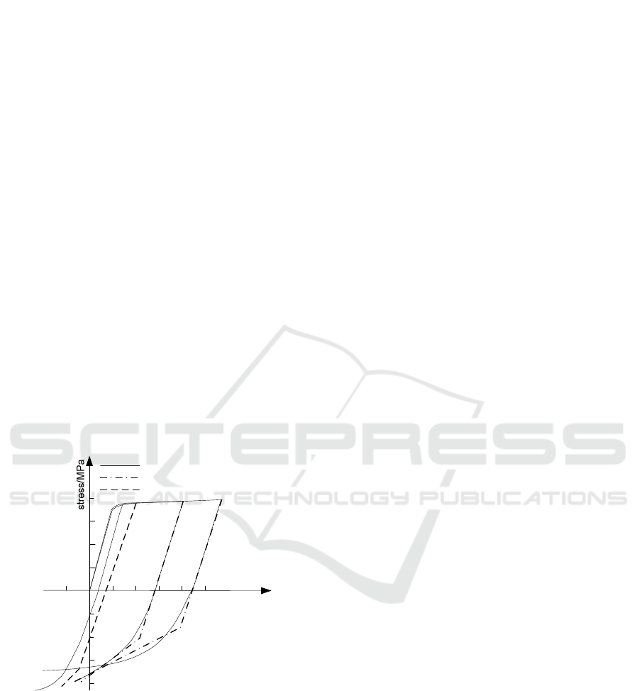
The stress-strain curve of the material is shown in
Figure 1. It clearly demonstrates the Bauschinger-
effect. Analysis procedure for autofrettage process
involves overstrain which is typically based on
Tresca or Von. Mises failure criteria. Here, using a
bilinear isotropic hardening model approximating
the real material behaviour is shown in Figure 1; has
been used in which E1 is the slope of the linear line
in the tensile elastic region (modulus of elasticity),
H1 is the slope of the linear line in the tensile plastic
region, E2 is the slope of the linear line in the
compression elastic region (modulus of elasticity),
and H2 is the slope of the linear line in the
compression plastic region. This material’s constants
are as follows: E1=206GPa; H1=2GPa; E2=207GPa;
H2=57GPa; σy1 =1103 MPa, σy2
=1100 MPa, where, v, σy1, and σy2 are the
Poisson's ratio , tensile yield stress, compression
yield stress, respectively.
300
600
900
1.20.6
1.8
2.4
3.0
-0.6
-300
-1200
Strain / %
-600
-900
uniaxial tension-compression
Fitting model
Calculating model
E
1
E
2
H
1
H
2
Figure 1: Material strain-stress curve.
2.2 Finite Element Model
The finite element model of TSEC has been
constructed in ANSYS APDL 15.0. The geometric
model is 1/4 of circumference of the cylinder, and
the element used here is 3D SOLID 186, and
mapped mesh method be used for easy simulation of
boring bore.
The cylinder body is mainly subjected to radial
force. During shrinking and autofrettage, the contact
surfaces are all one-way contact behaviors between
the surfaces, and the material of the three-layer
cylinder is also the same, so the contact can be
regarded as the “surface to surface” contact model of
the “Flexible-Flexible”. The target surface is the
inner surface of the middle layer and the outer layer;
The element type used is Target170. The contact
surface is the outer surface and middle surface, the
element type is Contact174. The geometric
dimensions of every cylinders was the actual
dimensions, including the initial mutual penetration,
and penetration tolerance was 0.0001 mm, and the
contact algorithm was chosen to be the Augmented
Lagrangian Method.
2.3 Boundary Conditions
Analytical model was the 1/4 of the extrusion
cylinder, so it is necessary to apply symmetry B. C.
on the corresponding surface. For easy solution,
assuming that the extrusion cylinder was in the plane
strain state, then axial displacement constraints has
been applied the both ends of cylinder.
3 SIMULATION AND RESULT
ANALYSIS
In the ANSYS environment, a number of
simulations have been performed on the shrink-fit,
autofrettage, boring and loading processes of
cylinder to calculate the residual stress distribution
in the shrink-fitted and multiple autofrettaged
compound cylinder and the maximum elastic
pressure capacity. Here the autofrettage pressure was
1800 MPa (pressurized system up to maximum
pressure).
First, having simulated the shrink-fit process of
the three-layer cylinder, residual hoop stress(RHS) is
shown in Figure 2(a). It reveals that the inner layer is
subjected to compressive stress with a large
value,and stress at the inner bore area (working area)
is 1150.94MPa, and the inner part of middle cylinder
is subjected to tension, and the outer part is
subjected to compression, and the stress value is
small, and the outer layer is subjected tension. Mises
stress is shown in Figure 2(b), and the maximum
stress is 1028.67MPa, and it is lower than
compressive yield limit of material, on this
condition, the entire cylinder is in elastic state.
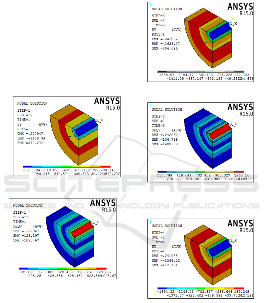
After the autofrettage process, the RHS of the
cylinder is shown in Figure 3(a), compared with the
stress after the shrink-fit, the residual compressive
stress of the inner cylinder is significantly increased,
and at the inner bore area is as high as 1638.07MPa.
The Mises stress is shown in Figure 3(b), and the
inner wall is up to 1409.59MPa, the inner part of the
inner cylinder has undergone reverse yield. after the
boring, the RHS of the cylinder wall is shown in
Figure 4, compared with the stress after once
autofrettage, the residual compressive stress is
reduced and it is reduced to 1594.32MPa. After
calculation [11], the elastic pressure of the cylinder
is 1553MPa.
(a)Hoop stress
(b)Mises stress
Figure 2: Residual stress of the shrink-fitted cylinder.
(a)Hoop stress
(b)Mises stress
Figure 3: Residual stress of once autofrettaged cylinder.
Figure 4: Residual hoop stress of once autofrettaged
and boring cylinder.
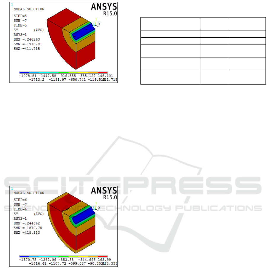
Figure 5: Residual hoop stress of double autofrettaged
cylinder .
In order to further enhance pressure capacity of
the cylinder, we investigated double and triple
autofrettage processes for the cylinder. The HRS of
double autofrettaged cylinder is shown in Figure 5,
compared with the stress of once autofrettaged
cylinder, the residual compressive stress of the bore
area increases significantly, with an increase of
340.74MPa. After the secondary autofrettage
simulation, the boring machining has been simulated
, the hoop compressive stress is 1870.75MPa ,
with an increase of 276MPa, as shown in Figure 6.
Figure 6: Residual stress of double autofrettaged
and boring cylinder.
The elastic pressure capacity(EPC) of the
different times autofrettaged cylinder is shown in
Table 1. EPC of the two times autofrettaged and
hole boring cylinder is 1710 MPa, EPC of three
times autofrettaged and hole boring cylinder is up
to1853 MPa. Since the strength is calculated by the
linear elasticity, the calculated value is slightly
lower than the actual value. It can be seen from
Table 1 that as the number of autofrettage increases,
the cylinder strength increases, but increment is
reduced.
Table 1: The RHS and EPC of different times
autofrettaged cylinder.
process
RHS
/MPa
EPC /MPa
Shrink-fit 1150 1300
Once autofrettage 1638 1578
Once autofrettage
and boring
1594 1553
Double autofrettage
and boring
1870 1710
Triple autofrettage
and boring
2120 1853
4 EXPERIMENTAL
VERIFICATION
The shrink fit process had been accomplished. The
cylinder was triple autofrettaged under pressure
1800MPa; Finally the inner hole was bored by 2mm.
when the operating pressure is 1800MPa, after the
pressure is released, the internal wall of the cylinder
can be fully recovered. It means that extrusion
cylinder elastic operating pressure can be up to
1800MPa, compared with the simulation value, and
the error is about 3%; Taking all differences of every
simulation value , the maximum error is about 5%,
which proves that the method and model in the paper
is correct.
5 CONCLUSIONS
Performing the autofrettage process to the shrink-fit
cylinder can increase hoop compressive residual
stress.
Multiple-autofrettage can further increase hoop
compressive residual stress, but as the number of
autofrettage increases, its increment is reduced.
Using the finite element model in the ANSYS
environment may better predict the residual stresses
of shrink-fit and autofrettage compound cylinder.
ACKNOWLEDGEMENTS
This project is supported by Shaanxi science and
technology research and development projects,
China (Grant No. 2013K08-14).

REFERENCES
1. Tae-hyuk, L., Moon-soo, S., Sin-hyeong, J., et al.,
2016. Effect of intermetallic compound thickness on
anisotropy of Al/Cu honeycomb rods fabricated by
hydrostatic extrusion process. Trans. Nonferrous Met.
Soc. China, 26, 456−463.
2. Hu, J., Lu, Y., Ren, Z., et al. 2014. Research progress
and application of hydrostatic extrusion technology.
Hot Working Technology, 43(15), 20-23.
3. Tian, Y., Cai, B., Qian, X., Liu, G., 2016. Hydraulic
extrusion technology of brittle superconducting
material. Ordnance Material Science and Engineering,
39(5), 58-61.
4. Lee, T., Sim, M., Joo, S., 2016. Effect of intermetallic
compound thickness on anisotropy of Al/Cu
honeycomb rods fabricated by hydrostatic extrusion
process. Transactions of Nonferrous Metals Society of
China, 26, 456−463.
5. Miraje, A., Patil, S., 2011. Minimization of material
volume of three layer compound cylinder having same
materials subjected to internal pressure. International
Journal of Engineering Science & Technology, 3(8),
26-40.
6. Miraje, A., Patil, S., 2012. Optimum thickness of
three-layer shrink fitted compound cylinder for
uniform stress distribution. International Journal of
Advances in Engineering & Technology, 3(2), 591-
605
7. Qian, X., Cai, B., Tian, Y., He, X., Sun, G., Yan, X.,
2014. Numerical simulation on influence of mold
parameters on stress field and mold pressure for
hydraulic extextrusion of tungsten alloys. Ordnance
Material Science and Engineering, 37(6), 97-100.
8. Urade, S., Bhope, D., Khamankar, S., 2015. Stress
analysis of multilayer pressure vessel. Journal of
Applied Mechanical Engineering, 04(2), 1-6.
9. Yuan, G., Liu, H., Wang, Z., 2010. Optimum design
for shrink-fit multi-layer vessels under ultrahigh
pressure using different materials. Chinese Journal of
Mechanical Engineering, 23(5), 582-589.
10. Yuan, G., Liu, H., 2012. An analytical solution of
residual stresses for shrink-fit two-layer cylinders after
autofrettage based on actual material behaviour.
ASME J. Pressure Vessel Technology, 134(06),
061209-1-061209-8.
11. Yuan, G., Guo, H., Wang, J., Guo, B., 2015. The
numerical analysis of residual stress and strength of
finishing high pressure cylinder. Machinery Design &
Manufacture, (03), 229-232.
