
Calibration of Parallelism Error About
R
otating Shafts Based on the
Three-coordinate Measuring Machine
Xinhua Zhao
1,2,3
, Liangping Ji
1,2,3
and Lei Zhao
1,2,3
1
School of Mechanical Engineering, Tianjin University of Technology, Tianjin 300384, China
2
Tianjin Key Laboratory for Advanced Mechatronic System Design and Intelligent Control, School of Mechanical
Engineering, Tianjin University of Technology, Tianjin 300384, China
3
National Demonstration Center for Experimental Mechanical and Electrical Engineering Education (Tianjin University o
f
Technology)
Keywords: Design; accuracy; measuring machine; parallelism; error calibration.
Abstract: The three-coordinate measuring machine is widely used in advanced manufacturing technology and
scientific research. Optimized design is extremely essential for improving accuracy of measuring machine.
According to the applied coordinate measuring machine’s structure, a method is proposed to realize the
calibration of parallelism error about rotating shafts. A large number of experiment and data have proved
that the proposed theory can quickly and efficiently complete the calibration work of parallelism error about
two rotating shafts. It posses some advantages such as easy operation, high flexibility and low cost. The
efficiency of calibration is also greatly enhanced.
1 INTRODUCTION
Accuracy is an important index to measure the
quality of measurement system. The accuracy of
modern industrial processing and detection precision
demand is higher and higher in the measurement
system. It is very important to reduce the error and
improve the measurement accuracy in practical
application[1-3]. There are many factors affecting
the mechanism error, and the structural parameter
error is one of the most important factors affecting
the measurement accuracy. At present, the
commonly used error calibration method is divided
into external calibration and self-calibration[4-5].
Theoretically, the external calibration adopts
precision measuring machine to obtain higher
calibration results, but the calibration cost is
expensive[6-7]. In response to these problems, based
on the actual structure of the measuring machine, a
method is proposed to realize the calibration of
parallelism error about rotating shafts based on the
applied coordinate measuring machine’s structure,
and completes the error calibration work.
2 THE STRUCTURE OF THE
MEASURING MACHINE
The measuring machine consists of five kinematic
pairs, namely two prismatic pairs and three revolute
pairs which move linearly along the X and the Z
direction. In the rotating shaft, the -axis and the B-
axis are theoretically parallel, and the axis of the A
axis is perpendicular to the B axis. The length of the
measuring rod is 250 mm and the length of the
cantilever is 500 mm, as shown in Figure 1. Due to
the installation error of the mechanism, the rotating
shafts the -axis and the B-axis are not completely
parallel. It can be seen from the reference that the
error caused by the rotation axis has the greatest
influence on the measurement accuracy, and with
the length of the link is gradually enlarged[8-9].
Therefore, it is particularly important to solve the
problem of parallelism error between two rotating
axes.
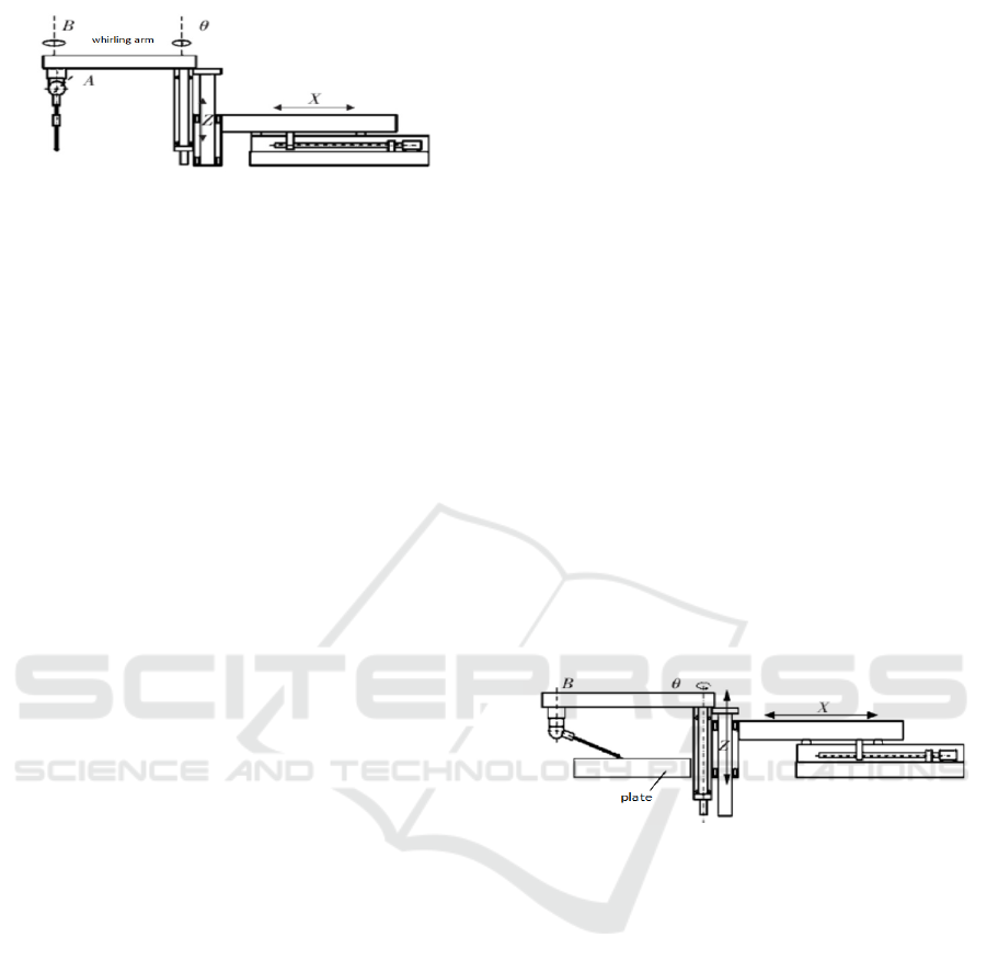
Figure 1: The structure of measuring machine.
3 PRINCIPLE OF PARALLELISM
ERROR CALIBRATION
There are many factors affecting the mechanism
error, and the structural parameter error is one of the
most important factors affecting the measurement
accuracy. At present, the commonly used error
calibration method is divided into external
calibration and self calibration. The external
calibration method is similar to the calibration
method of the traditional tandem mechanism. The
accurate external 3D measurement device is used to
estimate and calibrate the kinematic parameters of
the parallel robot. General use of laser
interferometer, theodolite and so on. The self-
calibration method is used to obtain redundancy
information about the position by the redundant joint
sensor of the parallel system. Theoretically, the
external calibration requires the use of highly
accurate precision measuring instruments or sensors,
fine adjustment and measurement results in higher
calibration results. However, the calibration cost is
high, and the actual accuracy is usually difficult to
achieve the expect effect in the worse calibration
environment. For the above reasons, aiming at the
parallelism error of rotating shaft, a calibration
method with low cost, high efficiency and low
environmental requirements is proposed in this
paper, which solves the existing problems of
external calibration.
In order to obtain the parallelism error between
the rotation axesθand B in the measuring machine, it
is necessary to obtain the perpendicularity
relationship between the two rotation axes and the
plane based on the same reference plane. It is
important to note that the accuracy of the plane is
higher than the accuracy of the measuring machine.
Therefore, using a high-precision plate as a standard
reference plane, the data detected by the probe on
the plate is obtained by rotating the two rotating
shaftsθand B respectively. By the least square
method, the perpendicularity relationship between
each axis and the reference plane, the plate can be
calculated. Finally, the parallelism error between the
two axes can be calculated.
3.1 The Perpendicularity Between the
Axis ofθand the Plate
In the measurement system, the rotation angle range
of the axisθis -120º~120º, the rotation angle range
of the axis B is 0º~360º, and the rotation angle
range of the axis A is 0º~120º. In order to measure
the relationship between the axis of the whirling arm
and the plate, the measure machine sends the probe
above the plate, as shown in Figure 2. Let the probe
be properly rearward, rotate 180ºabout the B axis
and 70ºabout the A axis. In this way, the whirling
arm can be shorten and the scanning range of the
probe can be increase; otherwise, a larger plate is
needed, and the cost is expensive.
Figure 2: Axis of whirling arm and the parallelism of Z -
axis.
The measuring rod is vertically falling down along Z
direction to the point where the measuring ball is in
contact with the plate, Rotating the rotating shaftθ,
record the coordinates of the probe on the panel
every 20°. Using the least square method fit to find
the normal direction of the forming plane, and it
represents the axial direction of the rotating shaftθ.
The two measurements date are shown in Table 1.
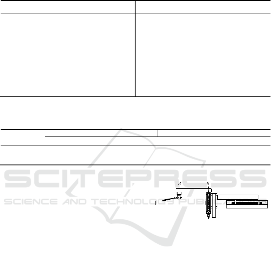
Table 1: The measurement data of whirling arm.
First measurement data Second measurement data
X/mm Y/mm Z/mm X/mm Y/mm Z/mm
652.8527 -519.2574 -103.6222 651.3632 519.9587 -99. 80469
738.4846 -459.1523 -103.4558 737.1935 460.1162 -100.0824
812.3357 -385.1113 -103.2305 811.3597 386.3012 -100.4047
872.1877 -299.3770 -102.9571 871.5892 300.7864 -100.7593
916.2238 -204.5483 -102.6344 916.0750 206.1492 -101.1384
943.1135 -103.5361 -102.2890 943.4800 105.2317 -101.5287
952.0455 0.5895 -101.9144 952.9548 1.1398 -101.9164
942.76967 104.6915 -101.5305 944.2203 -103.0000 -102.2908
915.5651 205.6187 -101.1400 917.5271 -204.0426 -102.6439
871.2652 300.3030 -100.7604 873.6930 -298.8837 -102.9623
811.2077 385.8848 -100.4026 814.0226 -384.6790 -103.2378
737.2077 459.7684 -100.0828 740.3389 -458.7936 -103.4626
652.1034 519.3504 -99.8066 655.4735 -518.6305 -103.6302
The plane normal vector value and the axis direction
of the rotate shaft and the corresponding angle of the
normal vector by fitting based on the measured data,
as shown in Table 2.
Table 2: The axis normal vector of rotation shaft θ.
Serial number The plane normal vector value Normal angle/(°)
I J K α β γ
1 -0.000675 0.003667 -1.000000 90.038693 89.789861 179.786328
2 -0.000669 0.003675 -1.000000 90.038372 89.789396 179.785929
average value -0.000672 0.003671 -1.000000 90.038533 89.789629 179.786123
3.2 The Perpendicularity Between the
Axis of Rotating Shafts B and the
Plate
The perpendicularity relationship between the axis B
of the rotating shaft and the plate is shown in Figure
3. Based on the above calibration principle and the
range of the B-axis rotation, the measuring rod is
rotated about 80°around the A-axis. The coordinate
of each point of that probe on the plate are recorded
every 10ºof rotation of the B axis, and the data of
two measurement are shown in Table 3 and Table 4.
The normal direction data of the circular section
is shown in Table 5.
Figure 3: The relationship of perpendicularity between
axis B of rotating shaft and the plate.
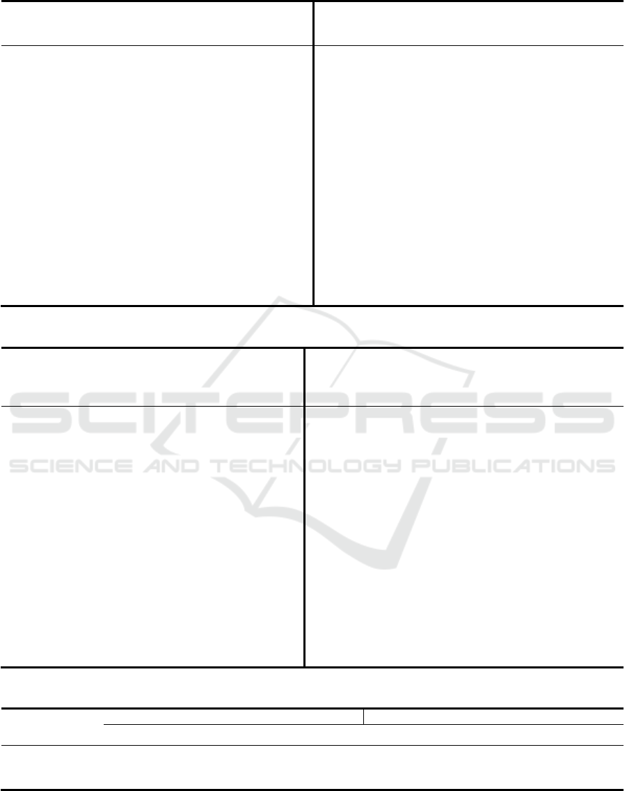
Table 3: The first measurement data of axis B rotation.
Rotation
angle of B
axis/(°)
X/mm Y/mm Z/mm Rotation
angle of B
axis/(°)
X/mm Y/mm Z/mm
0 556.6987 -44.1303 -103.9333 180 557.5235 404.9366 -101.0477
10 595.6403 -40.7952 -104.0142 190 518.5317 401.597 -100.9706
20 633.4609 -30.73622 -104.0426 200 480.7112 391.53569 -100.9395
30 668.9628 -14.2660 -104.0287 210 445.2132 375.06477 -100.9546
40 701.0622 8.1159 -103.9667 220 413.1104 352.6746 -101.01543
50 728.7859 35.73773 -103.8583 230 385.3833 325.0547 -101.1226
60 751.2850 67.7524 -103.7090 240 362.8753 293.0388 -101.2697
70 767.8961 103.1967 -103.5213 250 346.2632 257.5931 -101.4546
80 778.0986 140.9822 -103.3026 260 336.0622 219.8093 -101.6714
90 781.5782 179.9707 -103.0591 270 332.5765 180.8229 -101.9106
100 778.2532 218.9581 -102.8012 280 335.9122 141.8263 -102.1708
110 768.1982 256.7931 -102.5307 290 345.9676 104.0013 -102.4404
120 751.7292 292.2963 -102.2615 300 362.4361 68.4918 -102.7105
130 729.3521 324.3988 -101.9995 310 384.8170 36.3995 -102.9744
140 701.7347 352.1311 -101.7513 320 412.4334 8.6734 -103.2249
150 669.7192 374.6452 -101.5259 330 444.4498 -13.8370 -103.4527
160 634.2845 391.2501 -101.3286 340 479.8898 -30.4407 -103.6496
170 596.5041 401.4512 -101.1682 350 517.6703 -40.6397 -103.8132
Table 4: The second measurement data of axis B rotation.
Rotation
angle of
B
axis/
(
°
)
X/mm Y/mm Z/mm Rotation
angle of B
axis/(°)
X/mm Y/mm Z/mm
0 556.7003 -44.1307 -103.9356 180 557.5227 404.9366 -101.0470
10 595.6425 -40.7956 -104.0144 190 518.5330 401.5989 -100.9687
20 633.4599 -30.7400 -104.0452 200 480.7122 391.5391 -100.9380
30 668.9620 -14.2663 -104.0291 210 445.2156 375.0635 -100.9538
40 701.0631 8.1152 -103.9656 220 413.1110 352.6766 -101.0144
50 728.7844 35.7353 -103.8578 230 385.3840 325.0540 -101.1223
60 751.2892 67.7515 -103.7075 240 362.8752 293.0391 -101.2691
70 767.8984 103.1950 -103.5197 250 346.2628 257.5919 -101.4540
80 778.0968 140.9814 -103.3015 260 336.0630 219.8103 -101.6707
90 781.5806 179.9695 -103.0589 270 332.5788 180.8237 -101.9096
100 778.2512 218.9577 -102.7994 280 335.9113 141.8265 -102.1704
110 768.1989 256.7924 -102.5302 290 345.9649 104.0005 -102.4392
120 751.7310 292.2954 -102.2609 300 362.4351 68.4941 -102.7092
130 729.3484 324.3981 -101.9998 310 384.8170 36.3996 -102.9740
140 701.7326 352.1296 -101.7506 320 412.4319 8.6730 -103.2238
150 669.7200 374.6467 -101.5237 330 444.4517 -13.8363 -103.4516
160 634.2838 391.2508 -101.3288 340 479.8888 -30.4404 -103.6489
170 596.5043 401.4519 -101.1686 350 517.6717 -40.6387 -103.8132
Table 5: The normal vector of circular plane.
Serial number The plane normal vector value Normal angle/(°)
I J K α β γ
1 -0.002429 0.006443 -1.000000 90.139143 89.630848 179.605494
2 -0.002429 0.006446 -1.000000 90.139149 89.630673 179.605329
avera
g
e value -0.002429 0.006445 -1.000000 90.139146 89.630761 179.605412
Since the calibration of parallelism needs to
calibrate the deviations in two directions relative to
the reference plane, that is the X and Y directions,
this is different from the calibration of
perpendicularity error. Therefore, the deviation
angles of the axes of the two shafts relative to the

plate in the X and Y directions are given, as shown
in Table 6.
Table 6: The result of parallelism calibration.
Plate X-direction Plate Y-
direction
axisθ/( 〞)
-134.400 734.200
axis B/( 〞)
-485.800 -1 289.000
The axis of rotating shaft B produce an error
value is - 485.800 " in the X direction relative to the
plate and the error value is 1289.000" in the Y
direction. The deviation of the parallelism of the
rotating shaftθwith respect to the plate in the X
direction is - 134.400" and the deviation of the
parallelism in the Y direction is 734.200". Thus, the
parallelism error between the rotating shaftθand B is
362.099 " and - 572.488 2". The results show that
with the increase of the joint number and the gravity
of the mechanism itself, the parallelism error will be
amplified.
4 CONCLUSIONS
Through the above calibration method, the
calibration of parallelism error of rotating shafts can
be realized by using a high-precision plate.
Compared with the external calibration laser
interferometer, theodolite, etc. it is simple, easy to
operate, low requirements for environment, just
ensure the stability of the plate during measurement,
and the calibration cost is greatly reduced.
ACKNOWLEDGEMENTS
The authors acknowledge the National Key
Research and Development Program. (Grant No.
2017YFB1303502).
REFERENCES
1. Zhang Guo-xiong. Three-coordinate measuring
machine [M]. Tianjing: Tianjin university press, 1999.
2. Zhang Guo-xiong. Development trend of three-
coordinate measuring machine [J]. China Mechanical
Engineering, 2000, 11(2): 222-226.
3. Wang Cong-jun, Wei Lin, Li Zhong-wei.
Mathematical modeling and calibration method of
humanoid joint coordinate measuring machine [J].
Journal of Huazhong university of science and
technology: natural science edition, 2007, 35(17): 1-4.
4. Liu Dejun, Ai Qinghui, Wang Jianlin, et
al.Kinematic calibration and computer simulation of
3 DOF parallel-links CMM[J].Chinese Journal of
Mechanical Engineering, 2004, 40(3): 15-19.
5. Yu Lian-dong, Cheng Wen-tao, Fei Ye-tai. Parameter
calibration method for an articulated coordinate
measuring machine with laser tracker[J].Journal
of University of Science and Technology of China,
2009, 39(12): 1329-32.
6. Ren Yong-jie, Zhu Ji-gui, Yang Xue-you etc. The
method of calibrating robot by using laser tracker [J].
Journal of mechanical engineering, 2007, 43(9): 195-
200.
7. Ye Dong, Huang Qing-cheng, Che Ren-sheng.
Calibration of structural parameters of multi-joint
coordinate measuring machine [J]. Journal of
astronautic metrology and measurement, 1999, 19(6):
12-16.
8. Wang Ping-ping, Fei Ye-tai, Lin Chen-wang.
Optimization design of flexible three-coordinate
measuring arm precision [J]. Journal of applied
sciences, 2006, 24(4): 410-414.
9. Wang Xue-ying, Liu Shu-jia, Zhang Guo-xiong etc.
Research on calibration technology of multi-joint
flexible three-coordinate measuring system [J]. Journal
of Harbin Institute of Technology, 2008, 40(9): 1439-
1442.
