
Research on Dynamic Load of Flexibility Sliding Rail
Shuang Shi
1,2,
Hui Wang
1
, Dongmei Zhu
1
and Fei Peng
1
1
Anhui Sanlian University, Hefei, China
2
Qinghai University, Xining, China
Keywords: Fuze, Flexibility sliding rail, Deflection, Focus, Over loading.
Abstract: We propose a kind of plan with flexibility sliding rail for experimentation of the fuze in high speed
condition. Analyzing characteristic and environment factors of the rail, we reckon kinds of parameter based
on mechanics and material science. It is applied in the project. The result shows the method is effective.
1 INTRODUCTION
With the development of guided ammunition, fuze is
no longer a single device, but a complex system,
which is mainly composed of detection, signal
control and actuating mechanism, etc. [1]. Whether
the detonating time of fuze is coincident with the
design requirements and how to find the best kill
distance when ammunition is approaching arm.
Those urgent problems are all solved in fuze design.
These tests are usually completed under high speed
conditions. At present, it is usually adopted two
solutions to high-speed test: one is to use rigid slide
rail which is laid on the ground, and the experiment
is completed on rocket sleigh; the other is to use
flexible slide rail that is set up on cableway in the air.
The rigid slide raid can be used to achieve ultra-high
speed test. However, the construction of the slide
rail has very difficult. It has a rigorous condition to
ground, so It's almost impossible to finish in
mountainous and hilly areas. The use of flexible
slide rail can achieve slower speed than rigid slide,
but it is easier to build and lower in cost. Flexible
slide rail is applied to fuze test which works in low
speed, so the use of flexible slide rail is sufficient to
solve the test environment problems.
2THE BASIC STRUCTURE OF
FLEXIBLE SLIDE RAIL
The basic structure of the flexible slide rail is shown
in Figure 1. It includes the flexible ropeway and the
support device, the launching control platform, the
stop device, the instrument cabin, the data recorder,
the high-speed camera, the target and so on.
The target includes two parts: the ground target
and the air target. A hanger is built on the ground
target platform, and the target can be hoisted in air.
The arresting net has four layers. The first layer
adopts high strength arresting hook. The second
layer are set up with high-intensity parachute
behind the first layer a interval of 5m. Then, the
third layer are set up with high strength parachute
behind the first layer a interval of 3m. Finally, the
sand bag is placed in stop platform.
3PARAMETER ESTIMATION OF
INSTRUMENT CABIN
The equipment parameters are as follows in the
analysis and calculation.
The weight of instrument cabin is 20kg. It is
thrust forward by four engines of solid propellant,
and it is pushed reversely by two engines of solid
propellant too.

Figure 1The basic structure of flexible slide rail
3.1 Parameters of Engine
Parameters of thrust engine: thrust: 7889N; Working
hours:0.893s; Weight:8.8kg.
Parameters of reverse thrust engine: thrust :
3136N; Working hours : 0.64~1.2s; Weight:3Kg.
3.2 Estimation of Driving Distance and
Maximum Overload at Maximum
Speed
The formulas used are as follows[2]:
MaF
(1)
t
M
F
atv
(2)
2
0
2
0
2
1
2
1
t
M
F
tvattvS
(3)
Overload:
gM
F
(4)
Taking the engine parameters into (1), (2), (3),
(4), and
48
8.92.61
%9247889
)(189893.0
2.61
%9247889
2
1
)/(424893.0
2.61
%9247889
)(2.6148.82320
2
max
max
mS
smv
kgM
v
4ESTIMATION OF CABLE
TENSION
4.1 Analysis of Tension
When instrument cabin moves at high-speed, wire
rope’s deflection is generally 5%. If we ignore the
elastic of wire rope, instrument cabin as a rigid body
moves along an elliptical arc at high-speed (both
points on ends of wire rope is the focus of the
ellipse).Instrument cabin in moving generates a
centrifugal force against the wire rope, so the wire
rope sustain dynamic loading. Therefore, in order for
the rigid body to stick to the wire rope reliably, the
tension of the wire rope must be more than the
resultant force of centrifugal force, weight of the
wire rope and instrument cabin (as shown in Figure
2).
Figure 2 the wire rope
When calculating the tension of the wire rope,
only one steel cable is analyzed to ensure more
reliable and safe. The instrument cabin moves along
the elliptical arc ADCB. The M and N are the focus
of the ellipse and the pivot of the wire rope. A
coordinate system is set up, and the center point of

MN is origin O. When the instrument cabin’s
displacement is S (that is, when moving to the D
point), the force analysis is shown in Figure 3.
Figure 3wire rope force
The arc line ADC and the arc line CB are
symmetrical, and the maximum velocity of the
instrument cabin appears in the arc line ADC section,
so the mast tension of the wire rope only appears in
ADC section of the arc line. In the calculation,
ignoring the self weight of the steel cable
(considered by the constructor), when the instrument
cabin's displacement is S, the straight line L1 isthe
tangent line of the D point elliptical arc, and the
straight line L2 is the normal line of the D point.
Suppose G is the instrument cabin’s gravity; the
F is the centrifugal force; F1 and F2 are the tension
of the wire rope, and F1=F2.The short axis of the
ellipse is b, and b=OC; the focal length is 2c, and
2c=MN. So the long axis is a[3].
22
4
1
MNOCa
Equation of ellipse is
1
2
2
2
2
b
y
a
x
Suppose the D point coordinate is
),(
00
yx
, and
equation of the normal line of L2 is
)(
0
0
2
0
2
0
xx
xb
ya
yy
The slope of the normal line
0
2
0
2
1
xb
ya
k
The radius of curvature of D is
4sin
3
2
a
b
R
The coordinate of M is (-c,0), and the equation
of MD is:
00
y
y
cx
cx
The slope of a straight line is
cx
y
k
0
0
2
The resultant force of the wire rope in the
direction of the normal line is 0, so
3cos2cos21cos1
GfFF
Because of
R
v
Mf
FF
k
k
kk
kk
2
2
22
21
1cos4sin
11
1
3cos
12
|
2111
211
|1cos
So
|
211
211
|
2)21)(11(
)211(
2
1cos2
3cos
1
2
2
22
2
2
kk
kkG
v
kk
kk
b
aM
Gf
F
(5)
In the ADC, the force of the instrument cabin in
the tangent direction is similar to the thrust of the
rocket engine, so
(6)
The positive thrust of the instrument cabin is
;The negative thrust force for the instrument
cabin is ; The displacement of the instrument
cabin at the end of the positive thrust is
maxv
S
;The
time between the positive and negative thrust is
0
t
;
the maximum speed of the instrument cabin is
max
v
.
When
Scx
0
so,
22
0
)( cSa
a
b
y
.
According to the formula (5) and (6), the
function of F1 on S can be obtained.
(7)
4.2 Parameter Calculation
We can think that b is approximately equal to 23 and
suppose
0
t
is 0.1s, so
(8)
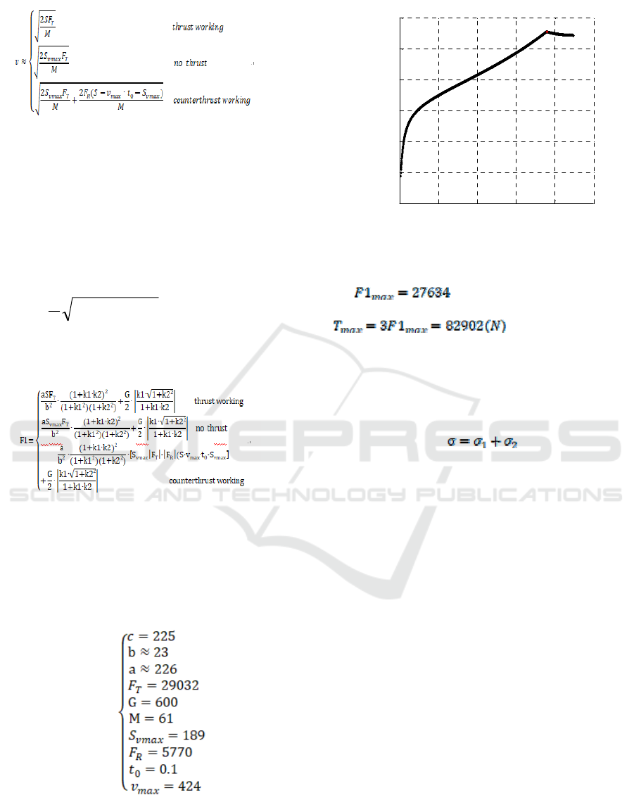
When the formula (8) inputs formula (7). The
value of the function is solved by programming as
shown in Figure 4.
0 50 100 150 200 250
0
0.5
1
1.5
2
2.5
3
x 10
4
S(m)
F1(N)
Figure 4Relationship between F1 and S.
So
, then, S=189.
Safety factor is 3, so
In the above calculation, the maximum dynamic
tension of the instrument cabin is
max
T
. The self weight of
the wire rope should be considered when the tensile
strength of the wire rope is designed.
Tensile strength is
5 CONCLUSIONS
Based on the theoretical analysis of the instrument
cabin and the wire rope, the dynamic pressure that is
generated by the instrument cabin along the slide rail
at the high-speed is calculated, so as to estimate the
tension of the wire rope. It provide parameters for
the strength design of the flexible slide rail. The
results have been applied in the actual construction.
When the weight of the instrument cabin or the
engine is adjusted for the different exam, the method
is also effective. However, friction and air resistance
are ignored in the calculation, so the calculation
parameters are not accurate enough. It will be
gradually improved in the next study.
ACKNOWLEDGMENTS
This research is supported by the fund of education
department of Anhui provincial (No. KJ2018A0599)
and National Nature Science Foundation of

China(No.51769027) and Anhui Sanlian
University(PTZD2018009).
REFERENCES
1. Qiang Huang. Structure and function of Aeronautical
ammunition[M]. The Equipment department of the
people's Liberation Army,1999.
2. Lai Wang, Yanming Wang. structural mechanics [M].
China machine press.2010.
3. mathematics manual [M]. People’s education press.
1979.
