
Fault Diagnosis of the CJ1 Flight Simulator Wheel
Guozhu Zhao
Civil Aviation Flight University of China Guanghan Sichuan, China
Keywords: CJ1 Flight Simulator; Wheel; Auxiliary operator; Amplifier.
Abstract: In the warranty period, the reward simulator makes a loud noise (mechanical friction sound), the fault is
serious, it cannot be balanced by electric power, and it can be balanced manually. The reset button cannot be
reset, and the reloading model cannot troubleshoot. Turn on the cockpit power cabinet and find the auxiliary
operator left amplifier error. The fault remains after the restart. After the amplifier is reset, the balance
wheel will automatically hit the low limit card to die. Let the auxiliary amplifier not work. At the bottom of
the simulator, the motor was found to be in the farthest position and could not be adjusted. Check the
mechanical structure drawing remove the wheel balancing observation found that main shaft screw loose,
tighten the screw, found that fastening balancing wheel can be normal, regardless of position or to be
obtained power balancing, without noise, troubleshooting.
1 INTRODUCTION
China's aviation maintenance market has great
potential, and the maintenance industry should
belong to the new industry, and the development
prospect is very promising[1-5]. Among them, the
maintenance prospect of the simulator is also very
promising [1-5]. Now flight simulator is mostly
mechanical, electronic, computer and automation,
and other more advanced technology in the
integration of high-tech products, its structure and
components are associated with complex, thus
caused by the failure type and failure causes are
complex and changeable. Many perspective from the
simulator fault detection, fault type, fault
phenomenon is various, and the same causes of the
failure phenomenon and may be varied, so the
analog fault diagnosis and maintenance process is
very complex [6-8].
The CJ1FFS simulator is in the warranty period
with a loud noise (mechanical friction sound), which
seriously affects the flight. It is normal to work
when the balancing wheel is rotated, but mechanical
noise can occur when it is rotating at high speed or
using electric power. It may occur because of
damage to the buckles (broken gear).The fault
occurs because the output force of the motor exceeds
the range that the gearbox can handle when the fault
is blocked. This could cause the gearbox to fail. And
that's why the chain is getting longer and longer,
because there's torque in it. MSI, a simulator
manufacturer, suggests that the chain should be
replaced, and the use of PD1 lubricating oil to
lubricate it quarterly will increase its service life.
On top of that, the clutch on the motor's link
shaft needs to be tightened. However, if the
balancing wheel is too tight, it may be difficult for
the balancing wheel to be manually operated, so
some tests and attempts are needed to obtain the
correct tension on the balance wheel. This means
you need to open the central console. The gear has
no gear box. The chain cannot be tightened through
the position of the moving motor because the motor
is already at the far end. Changing the chain is
difficult and difficult to operate. We can't tell if the
gear is damaged or not, because the gears are inside
the center console. Flight simulation equipment is
mainly divided into flight simulator, fixed simulator
and dynamic simulator. Since the first flight
simulator was put into operation in the last century,
the simulator has made continuous progress in both
hardware and software technology, especially in
software technology.
Over the past ten years, more manufacturers have
been involved in the R & D and production of
simulators, and the simulation equipment with
independent intellectual property rights has been
designed and used in China. For example, in

December 2005, huawing blue sky Co., Ltd.,
cooperated with the three parties of CAAC and
CAAC, and launched the company's "Boeing
737NG simulation flight training equipment"
independently developed by the company. The
device uses the core software of the "virtual flight
trainer" of the Chinese wing blue sky company,
designed according to the features of the Boeing 737
aircraft, and is a second series of products adapted to
the needs of large civil aviation aircraft in China,
and the equipment has been delivered to the flight
Institute to use [2]. As shown in Figure 1, a large
number of new technologies and ideas are adopted
in the new simulator, especially the overall progress
of the computer system, the visual system, the flight
control system, the interface system, the motion
system, the instrument system and the software
development model technology. On the basis of
inheriting the advantages of the traditional analogue
machine, the technology breakthrough has been
achieved in [3].
The control system provides the pilots with the
rod and rudder, and the control feedback force of
other equipment. The real degree directly affects the
performance of the simulator. There are many tests
on the QTG flight quality objective evaluation
system. Recently, the electric control system has
gradually replaced the traditional hydraulic control
system. The early electric control system adopts
DSP and simple embedded control program. It is
difficult to develop and debug the system. The
ECOL-8000 system adopts a common industrial PC
machine, which has PCI slot and multiple
professional AD-DA conversion cards.
The interface system is the main channel for data
exchange and communication between simulator PC
and avionics equipment in the cockpit. In recent
years, the serialization trend of the interface system
has been popular, especially the application of USB
interface has promoted the adoption of the industrial
standard serial bus.
The Canadian Mechtronix simulator
manufacturing company used 4 ports and nearly 100
Canbus nodes on its B737-800 simulator. Every
simulation instrument and panel has a single chip
computer with Canbus interface, which is
communicated with PC through the bus. Canada's
CAE simulator manufacturing company uses the
plug and play USB bus to maximize the convenience
of troubleshooting. The use of "HOST TO PANEL"
makes each cockpit panel become a USB device,
which is directly communicated with PC, and the
failure of a single excuse unit will not affect the
normal operation of the entire interface system.
2 RESEARCH SIGNIFICANCE
Fault phenomenon: the balancing wheel makes a
loud noise (mechanical friction sound), cannot be
balanced by electric power, and can be balanced
manually. In this paper, the research for the
improvement of China's civil aviation college of
flight simulator training center, maintenance,
operation efficiency, and save the maintenance cost
plays an important role, and lay the foundations for
the subsequent series of the maintenance of the
simulator.
The computer system is mainly responsible for
the calculation of flight simulation and the exchange
of data with the interface system. The complex
computing and graphic display which needed
expensive computer workstations to be
accomplished by expensive computer workstations.
Now it only needs to buy ordinary personal
computers to complete the distributed multi
computer network with multiple computers in a
single cabinet or multi cabinet. The simulator system
is becoming the mainstream [4]. In this system,
different computers are responsible for different
tasks through data exchange and synchronization.
The visual system is responsible for the
simulation of visual images, which provides virtual
external world for pilots. The image generation
system is responsible for real-time 3D image
generation, and the projection system is responsible
for projecting real-time 3D images onto the 180
degree ring surface screen. The progress of the
visual system mainly includes the progress in these
three aspects. The widely used "three gun"
kinescope projection system has gradually been
replaced by silicon based LCD projector [5].
The new LCOS projector has great progress in
these three aspects, such as the DLA-HD10K
projector of JVC company used by RSI company's
visual system, which uses non mobile mirror
technology, with color stability, high resolution,
resolution up to 1920 x 1080, contrast to 2500:1,
with cinema level color grade and black. The color
gamut shows the effect. This type of projector has
finally replaced the "three gun" projection system,
which has been widely used in the high-end flight
simulator. Pilots fly to all parts of the world, and the
terrain and geomorphology they see are close to the
virtual environment brought by the simulator. The
effect of simulated flight training is largely
influenced by the quality of the visual image, and
the quality of the visual image depends on the
completion of the debugging work. At the same
time, the image debugging work is big, the

requirement is high, and it has certain risk.
Therefore, in the process of debugging, we should
be careful and patient, and use all kinds of
debugging techniques and means reasonably to get
the best effect [6].
The sports system provides pilots with other
kinds of flight sensation such as jolting in flight. In
the motion system, the electric motion system begins
to replace the hydraulic motion system gradually.
Compared with the hydraulic motion system, the
system has the advantages of saving electricity, low
noise, no pipe pollution and no oil leakage.
However, the electric motion system is still a new
thing, and its technology is not very mature, in
which the supply of parts is a problem. The problem
of traditional hydraulic systems is basically not [3].
3 FAULT ANALYSIS
The control system provides the pilots with the rod
and rudder, and the control feedback force of other
equipment. The real degree directly affects the
performance of the simulator. There are many tests
on the QTG flight quality objective evaluation
system. Recently, the electric control system has
gradually replaced the traditional hydraulic control
system. The early electric control system adopts
DSP and simple embedded control program. It is
difficult to develop and debug the system. The
ECOL-8000 system adopts a common industrial PC
machine, which has PCI slot and multiple
professional AD-DA conversion cards.
The interface system is the main channel for data
exchange and communication between simulator PC
and avionics equipment in the cockpit. In recent
years, the serialization trend of the interface system
has been popular, especially the application of USB
interface has promoted the adoption of the industrial
standard serial bus. The Canadian Mechtronix
simulator manufacturing company used 4 ports and
nearly 100 canbus nodes on its B737-800 simulator.
Every simulation instrument and panel has a single
chip computer with canbus interface, which is
communicated with PC through the bus. Canada's
CAE simulator manufacturing company uses the
plug and play USB bus to maximize the convenience
of troubleshooting. The use of "HOST TO PANEL"
makes each cockpit panel become a USB device,
which is directly communicated with PC, and the
failure of a single excuse unit will not affect the
normal operation of the entire interface system.
Cockpit meters provide various parameters to
provide various dynamic data for pilots. From the
development of the instrument system in the past
few years, the traditional simulator used a large
number of real aircraft electric instruments. Because
of the complex structure, the difficulty of driving,
the high maintenance cost, the simulation
instruments are gradually using the simulation
instruments. The appearance and performance of the
simulation instruments are the same as the aircraft
instruments, but the maintenance is maintained. It's
more convenient. The use of the simulation
instrument will no longer need to drive the
instrument through the ARNIC-429 and other buses
which are unique to the simulated aircraft, and no
longer need the 115V/400HZ power supply, and the
system failure rate will be further reduced. In
particular, modern aircraft gradually use flat
instruments, which are suitable for computer
graphics.
4 REMOVE STEPS
The reset button cannot be reset, and the reloading
model cannot troubleshoot.2. Open the cockpit
power supply cabinet to find the auxiliary operator
left amplifier error, error code: 51. 3. After the
amplifier is reset, the error code will be converted
between 91 and 72, and the balancing wheel will
automatically hit the low limit card to die. Card after
death error: 72. 4. The flight crew requires to
continue to fly, turn off the CB1 switch, and let the
auxiliary amplifier not work. in the process of doing
QTG find balancing wheel and the mechanical
noise, the simulator observation found at the bottom
of the motor is in position, can't adjust, chain loose
problem failed to solve for the time being.2, remove
the balancing wheel to observe the mechanical
structure, found that main shaft screw loose, tighten
the screw, found that fastening balancing wheel can
be normal, regardless of position or to be obtained
power balancing, did not happen, noise fault a
temporary solution, for further research and
treatment.
Open the instrument panel, found that the main
shaft screw is loose, unable to tighten, prompted a
twisting balancing wheel mechanical position
phenomenon, find the reasons, found that the tail
and central axis of the screws are loose.2. Tighten
the two screws, the spindle is no longer loose;3. The
chain is noticeably loose from the 227 model, which
is temporarily not processed, and the chain is
lubricated by oil.
At present, the overall debugging is normal,
whether it is electric balancing or manual balancing,
no abnormal sound is found; Relocations and no
mechanical noise.5. Install TCAS panel and FMS. 6.
Install the front cover, left and right side cover, and
install the knob.
When the balancing wheel turns, the CB1 switch
of the SCL will be turned off, and the manual
balance will be temporarily used.2. Mechanical
noise appeared at around 6 o 'clock on April 18th,
but recently, the balancing wheel was observed and
the operation was good.3. For the sake of safety, 20
orders of original screws have been ordered, and the
order sheet has been delivered to the shipping
materials. The number of the order is 171-
00000147-00-000.4. After the mechanical noise was
found in the balancing wheel, two new screws were
found to be broken again, and the spindle was found
to be loose, and the gear could not be fastened, and
the suitable solution could not be found for a while.
The abnormal condition was found before the
balancing wheel was disassembled, with 3 screws
falling in the ground; After fastening, check the
cal_0.dat file of SCL and recalibrate the position
data of the balancing wheel.-720 degrees and 1280
degrees are recalibrated. Reload the program again,
test the balancing work is normal.2. It is found that
the two adjacent screws of the balancing wheel have
already been broken, and it is speculated that the
fault of the balance wheel in the near future is
caused by two broken screws: the failure of the
screw causes the torque to push the pointer not
enough.3. Only two screws are fastened, the
balancing wheel can work normally, the needle is
working normally, and the other two screws will be
replaced next time.
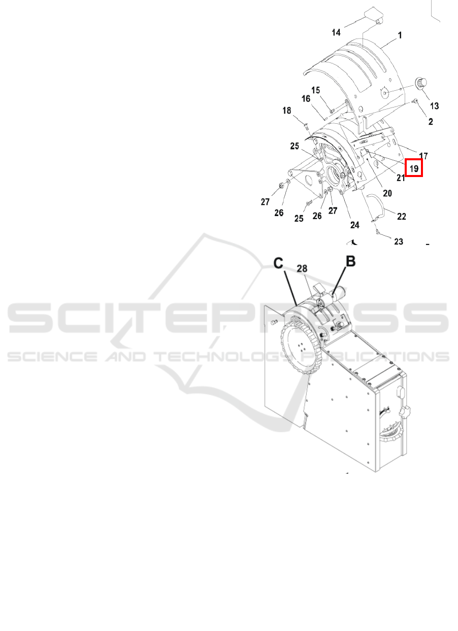
Fig. 1 the structure diagram of the balance wheel.
Remove the balancing wheel, select the take-off
position and fix its position.2. Recalculated, found
that there was mechanical noise inside the reloading
model, and suspected that there was mechanical
failure around the motor, and the process was
disassembled when scheduled maintenance on May
2nd.
Find that the balancing wheel is loose, and when
it is tightened again, the wheel is no longer
skidding.2. Once again disconnect the auxiliary
computer and restart it, enter the SCL-TEST and

restart the SCL computer after calibration of the
upper and lower positions. After loading the
program, the TEST work is normal. If it is found
that the balance wheel is loose, please tighten it in
time to prevent the deviation after slipping. Check
the cal_0.dat file of SCL. Observe the position data
of the balancing wheel, and the number of two
positions in the two positions of 720 degrees and
1280 degrees is recalibrated by the operation of the
SCL test program.2. After power failure of SCL
computer, reload the program again, the fault
remains.
3. Repeat the above method, and power off and
power on the operation, test the balance, the fault is
still, and cannot be balanced by electric power.4.
Since it has already arrived at 2 o 'clock in the night,
we will be excluded next time. Check the operation
manual of the auxiliary operating amplifier of the
balancing wheel.
5 CONCLUSIONS
The reset button cannot be reset, and the reloading
model cannot troubleshoot. Turn on the cockpit
power cabinet and find the auxiliary operator left
amplifier error. The fault remains after the restart.
After the amplifier is reset, the balance wheel will
automatically hit the low limit card to die. Let the
auxiliary amplifier not work. At the bottom of the
simulator, the motor was found to be in the farthest
position and could not be adjusted. Check the
mechanical structure drawing remove the wheel
balancing observation found that main shaft screw
loose, tighten the screw, found that fastening
balancing wheel can be normal, regardless of
position or to be obtained power balancing, without
noise, troubleshooting.
ACKNOWLEDGEMENT
This work was financially supported by fund project
of Civil Aviation Flight University of China
(Q2018-170) and (J2015-63). Helicopter multi
mission flight training device development, civil
aviation innovation and guidance fund projects
major projects ( MHRD20130108 ).
REFERENCES
1. Research on a Case-Based Decision Support System
for Aircraft Maintenance Review Board Report
LNCS 4113, pp, Springer-Verlag Berlin
Heidelberg,2006:1030-1039
2. Miehael MasuehM LaszloPolos. Knowledge
representation and reasoning under uncertainty. New
York: Springer- Verlsg,1999.276~288
3. Watson I, Mariri F, Case-Based Reasoning : A
Review,Knowledge Engineering Review,1994,
(4): 327-54
4. A.1.Meehitov and H. M. Moshkovieh. Knowledge
Aequisition Tool for Case-Based Reasoning System.
Expert System with Application, 1998, vol.8:201-
212
5. Chu Shu-chuan,Roddick J F, Tsong-Yi Chen, et al,
Efficient Search Approaches for K-medoids-based
Algorithms, TENCON '02, Proceedings, 2002 IEEE
Region 10 Conference on Computers,
Communications, Control and Power Engineering,
2002,1:712-715
6. Aamodt, and Plaza. Case-based Reasoning :
Foundational issues,methodological variations, and
system approaches. AI Communications, 1997,
vol.7:39-52
7. Kyung shin, Ingoo Han. A Case-Based approach
using inductive indexing for corporate bond rating.
Deeision Support Systems, 2001.41-52
8. Isermann. On the applicability of model based fault
detection for technical process. Control Engineering
Practice,1999.439-450
9. Hei-Chia Wang, Huei-Sen Wang, A hybrid expert
system for equipment failure analysis, Expert
System with Application, 2005(4):615-622
