
New Design of Directional Coupler Based on Ridge-waveguide
Chengfang Fu
1
, Bo Zhao
1
1
Faculty of Electronic Information Engineering, Huaiyin Institute of Teconology, Huaian, China
Keywords: Ridge Waveguide, Directional Coupler, Coupling, Chebyshev Function.
Abstract: Ridge waveguide devices are used extensively in microwave system because with the same section size,
ridge waveguides have relatively wider single-mode bandwidth than rectangular waveguides. A new method
for designing a directional coupler whose main and vice-waveguide are both ridge waveguide is presented,
mean while, Chebyshev function is used as distribution function. The designing of the coupler is simulated
by HFSS.
1 INTRODUCTION
A number of scholars have been systematically
studied the design of directional couplers, especially,
the main and vice-waveguides of the directional
coupler are rectangular waveguide. But main and
vice-waveguides are ridge waveguide is relatively
rare. The boundary conditions of ridge waveguide
are more complex, it is quite difficult to analytic
solution to the field of the ridge waveguide, which
limits the study and applications of the ridge
waveguide. Ridge waveguide is divided into the
ridge area and the slot area by W. J. Getsinger, and
the transverse electric field is matched to deduce the
analytical expression to descript the ridge
waveguide, which laid the foundation to study ridge
waveguide[Getsinger, 1962].
The Chebyshev function has been proposed as a
distribution function by scholars in the study of
microwave devices, which can improve the device
performance. Therefore, the pore size distribution of
the holes is on the Chebyshev function, a directional
coupler device of the center frequency of 3GHz, the
coupling of -40dB is designed using the small hole
coupling theory. HFSS simulations show that such a
design in a wide frequency range, the coupling is
relatively flat.
2 MAIN BODY
2.1Calculation of
±
v
A
[Miller, 1954]
The main and vice-waveguides of the multi-hole
directional coupler are in the fundamental mode of
the waveguide. Coupling holes are relatively
symmetrical distribution to the centerline, not only
the locations of each pair of symmetrical holes
symmetry, but also the shape and size of them are
symmetry. The main waveguide excites the
fundamental positive and anti-wave through those
coupling holes in the vice waveguide, respectively,
whose relative intensity are
±
0
a
,
±
1
a
…
±
n
a
,
where the superscript
±
are the positive and reverse
wave, respectively, the subscript are the coupling
hole number, the total number of coupling holes is
12 += nN
.
Figure 1: Multihole directional coupler.
The voltage of the positive and reverse wave
which are excited by the modes of the main
waveguide m in the vice waveguide[Wang
Wenxiang, 2003].
d
2
d
n
d
k
d
1
S
k
S
n
S
1
S
2
S
2
S
1
S
k
S
n

0
112 2
0
1
2 cos 2 cos
2 cos 2 cos
2cos
v
kk nn
n
kk
k
Aa
aa
aa
aa
θθ
θθ
θ
±±
±±± ±
±± ±±
±±±
=
=+
++
+++
=+
∑
L
L
(1
)
Where
⎪
⎭
⎪
⎬
⎫
=
=
∑
=
±
n
k
kk
kvmk
Sd
d
1
2
2/)(
ββθ
m
(2)
2.2Determination of S
In multihole coupling the space between the
coupling holes
k
S
are equal and the space is
S
,
which is the pitch coupling, so
kSd
k
2=
(3)
±
±
=
ϕθ
k
k
2
(4)
where
2/)( S
vm
ββϕ
m=
±
(5)
When
πθ
kk
i=
+
,
),2,1,0( L=
k
i
, when, all
the positive waves are overlaying, while when
πθ
)2/1( +=
−
kk
i
,
),2,1,0( L=
k
i
, all the
reverse wave are to offset each other(
0
a
is
excepted). Therefore, according to the above
conclusions, selecting the appropriate value
k
i
, the
hole spacing
S
can be got.
2.3Calculation of the Single-hole
Coupling Coefficient
In order to improve the performance of the
directional coupler, the coupling strength of the
coupling region is set to change according to some
certain laws. To this end, the hole spacing is fixed
unchanged, leaving the pore size changes according
to certain rules, that is the different aperture holes
are arranged so that the coupling strength of the
coupling region to meet a certain distribution. We
use the Chebyshev distribution law to arrange the
pore size of the hole [Levy, 1959, Jiang P Y, 2004].
For the equal spacing ranging and the unequal
intensity distribution, there are the following
equations.
±
±
±
±
±
±
=== aaaaaa
nn
δδδ
,,,
1100
L
(6)
While (1) changes into
∑
=
±±
±
+=
n
k
kv
kaA
1
0
)2cos(2
ϕδδ
(7)
First Chebyshev function is defined as
)arccoscos()( xnxT
n
=
)1( ≤x
(8)
When
−
=
ϕ
cosx
, so
1≤x
,and
∑
=
−
−
+=
n
k
kkv
xTxTaA
1
200
)(2)(
δδ
(9)
The reverse incentives
−
v
A
are limited not
exceed a certain maximum value within a certain
range, so the result is
)(
2
txTKA
nv
=
−
(10)
According to experience, t is set as 1.5, then
equal the functions (9) and (10), making the
corresponding coefficient equal, then
n
δ
δ
δ
L,,
10
can be obtained when the number holes is N
))2cos(2/(10
1
0
20/
∑
=
±+
+=
n
k
k
C
ka
ϕδδ
(11)
where C is the coupling coefficient of the directional
coupler (dB). From the coefficient
n
δ
δ
δ
L,,
10
,
the coupling coefficient of the single hole can be
calculated.
2.4Calculation of the Single-hole Radius
According to the field expressions of the ridge
waveguide[Getsinger, 1962] and small hole coupling
xarccos=
−
ϕ

theory[Bethe, 1944, Collin, 1966], the relative
amplitude of the waves of the vice-waveguide:
kkk
aaa
,2,1
m=
±
(12)
where
1
1
1
1
3
1, 0
2
2
2
1
cos / 2
sin
sin
cos / 2
2
sin sinh cos
sinh
2
3
cos / 2
sin
sin
cos / 2
2
sin sinh cos
sinh
c
c
c
c
n
n
n
kkee
s
c
c
c
c
n
n
n
dks
kx
bkl
ks
nynd
x
nlb b
j
arKR
p
dks
kx
bkl
ks
nynd
x
nlb b
ππ
γ
πγ
ω
ε
ππ
γ
πγ
∞
=
∞
=
⎧⎫
⎡⎤
+
⎪
⎢⎥
⎪
⎢⎥
×
⎪
⎢⎥
⎪
⎢⎥
⎪⎣ ⎦
=−
⎨
⎡⎤
⎪
⎢⎥
⎪
⎢⎥
⎪
⎢⎥
⎪
+
⎢⎥
⎪
⎣⎦
⎩
∑
∑
⎪
⎪
⎪
⎪
⎪
⎬
⎪
⎪
⎪
⎪
⎪
⎭
(13)
2
22
1
1
1
2
3
2
2, 0
1
cos / 2
sin
sin
cos / 2
2
sin sinh cos
sinh
cos / 2
sin
sin
cos / 2
2
4
sin sinh cos
()
sinh
3
c
c
c
z
c
n
n
n
c
c
c
c
n
kkmm
n
n
s
dks
kx
bkl
k
k
ks
nynd
x
nlb b
dks
kx
bkl
ks
ny
nd
j
x
arRK
nlb b
p
η
ππ
γ
πγ
π
π
ω
γ
μ
πγ
∞
=
∞
=
⎧
⎡⎤
⎪
⎢⎥
⎪
⎢⎥
×
⎪
⎢⎥
+
⎪
⎢⎥
⎪⎣ ⎦
⎨
⎡⎤
⎢⎥
⎢⎥
⎢⎥
+
⎢⎥
=−
⎣⎦
∑
∑
2
2
22
1
1
1
1
2
2
1
1
cos / 2
cos sin /
2
cosh cos
sin sinh
cos sin /
2
cosh cos
sin sinh
c
c
cc
n
n
cnn
cc
n
n
cnn
k
ks
k
dkx k ndb
ny
x
bkl n l b
dkx k ndb
ny
x
bkl n l b
η
π
π
γ
πγ γ
π
π
γ
πγ γ
∞
=
∞
=
⎧
⎫
⎪
⎪
⎪
⎪
⎪
⎪
⎪
⎪
⎪
⎪
⎬
⎪
⎪⎪
⎪
⎪⎪
⎪
⎪⎪
⎪⎪
⎪⎪
⎨
⎩⎭
⎧⎫
×
⎪⎪
⎪⎪
⎪⎪
⎡⎤
⎪⎪
−− ×
⎨⎬
⎢⎥
⎣⎦
⎪⎪
⎪⎪
⎡⎤
⎪⎪
−
⎢⎥
⎪⎪
⎣⎦
⎩⎭
∑
∑
⎫
⎪
⎪
⎪
⎪
⎪
⎪
⎪
⎪
⎪⎪
⎪⎪
⎬
⎪⎪
⎪⎪
⎪⎪
⎪⎪
⎪⎪
⎪⎪
⎪⎪
⎪⎪
⎪⎪
⎪⎪
⎩⎭
(14)
where
s
p
is the normalized power coefficient.
mmee
RKRK ,,,
are the factor and the thickness of
the macro-hole factor[Sporleder, 1979].
11
, yx
are
the locations of the holes in the main waveguide,
22
, yx
are the position of the vice-waveguide. From
(12) and the single-hole coupling coefficient from
above calculation, the aperture of the hole can be
obtained.
3DESIGN EXAMPLES
3.1Design of an Example
The example directional coupler is set at the center
frequency of 3GHz, the coupling is -40dB, so the
standard single-ridge waveguide is chosen, the
single-mode operating frequency range of the
waveguide is 2.0 ~ 4.8GHz. The design directional
coupler structure is as follows (Unit: inch)
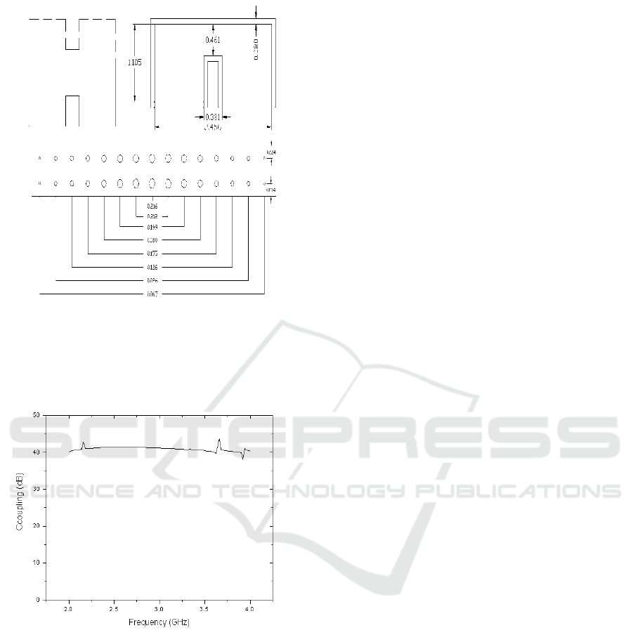
Figure 2:The structure and dimension of the directional
coupler.
3.2Simulation Results
Figure 3:Coupling of the directional coupler versus the
frequency.
It can be seen from the above simulation results
figure that the coupling curve is relatively flat in
broad frequency range, so our design method is
feasible.
4CONCLUSIONS
It can be seen that when the coupling hole is two
rows, each row is set as 15 holes, the radius of the
center hole is 0.216 " in our example design. If the
coupling is stronger, the aperture and the number of
holes are need to increase. When the aperture is
increased, then the aperture is too large, the small
hole coupling theory is no longer reasonable. If the
number of holes is increased, not only the
fabrication becomes more difficult, but also the
coupler length will increase. Therefore, the design
method of the directional coupler whose main and
vice-waveguides are ridge waveguide based on the
small hole coupling theory is feasible only for the
case of weak coupling.
REFERENCES
1.
Getsinger W J,1962.Ridged waveguide field
description and application to directional couplers.
IRE Trans. Microwave Theory Tech., 1(MTT-10) ,
pp.41-50.
2.
Miller S E.,1954. Coupled wave theory and waveguide
applications. BSTJ, pp.661-719.
3.
Wang Wenxiang, Gong Yubin, Yu Guofen, et al.2003.
Mode discrimination based on mode-selective
coupling. IEEE Trans. on MTT,51(1), pp.55-63.
4.
Levy R, 1959. A guide to the practical application of
Chebyshev functions to the design of microwave
components. The Institution of Electrical Engineers
Monogragh, 6(337E) , pp.193-199.
5.
Jiang P Y,2004. The optimal design of the broadband
mode discriminators. B. S. thesis. University of
Electronic Sience and Technology of China.
6.
Bethe H A, 1944. Theory of diffraction by small holes.
Physics Review, 66, pp. 163-182.
7.
Collin R E, 1966. Foundations for Microwave
Engineering. McGraw-Hill, New York, 2
nd
edition.
8.
Sporleder F, Unger H G,1979. Waveguide tapers
transitions and couplers. Peter Peregrinus Ltd. London,
1
st
edition.
