Research on the
K
ey Technology for Robot Intelligent Welding of
Q235-Hydraulic Oil Tank
Hao Wang
1,2
,Junjian Lin
1
,Qingfang Qiu
1
,Xin Wei
2
and Fei Cao
1
1
Sinomach Intelligence Technology Co., Ltd
,
Guangzhou Guangdong, 510700
2
School of Electro-mechanical Engineering, Guangdong University of Technology
,
Guangzhou Guangdong, 510006
Keywords: Hydraulic oil tank; Robot arc welding; Process test; Flexible fixture.
Abstract: To solve the problems such as low welding efficiency, poor welding molding quality in manual welding of
hydraulic oil tank, this paper conducts a research on intelligent robot welding technology for hydraulic oil
tank. Aiming at these problems of various types and non-standard sizes of the tanks,this paper designs a
flexible fixture for the tanks, and studies the influence between the weld quality and the welding speed,
current, voltage, protective gas, and other process parameters through the welding experiment, finally a set
of robot welding technology of hydraulic oil tank which in the size of 1000mm×500mm×500mm is formed.
1 INTRODUCTION
The hydraulic oil tank as a key part of the hydraulic
system, played a crucial role in storage of hydraulic
oil, transmission and ensure the normal operation of
the hydraulic system. Therefore, the hydraulic oil
tank has a particularly high for welding quality
especially air tightness requirements after welding.
At present, the welding of hydraulic oil tank
mainly depends on the traditional manual arc
welding, some of which are introduced into robot
welding, and the welding material usually faces up
to 3mm thick plate. Due to the large thermal
influence zone in the process of arc welding, the
thermal deformation of the workpiece is large,
which can produce the complex residual stress,the
welding seam is poor and needs polishing after
welding. It is easy to form porosity, slag, unmelted
and unsoldered welding defects during the welding
process. In severe cases, minor cracks occur, causing
oil spills in the tank, which causes serious safety
problems to the stability of the hydraulic system.
Therefore, the research on high quality and high
efficiency welding technology of hydraulic oil tank
is very important to maintain the stability and safety
of hydraulic system.
Robot welding with its high speed, high quality,
good flexibility, easy to realize automation, is
widely used in shipbuilding, weapons and
equipment, marine engineering, automobile industry,
railway vehicle, hydraulic equipment manufacturing
and other fields, occupies a significant role in
manufacturing.Taking the hydraulic oil tank as
research object, this paper carried out the research
through the welding process, welding seam tracking
technology and flexible fixture design.
2 WELDING SYSTEM AND
MATERIAL
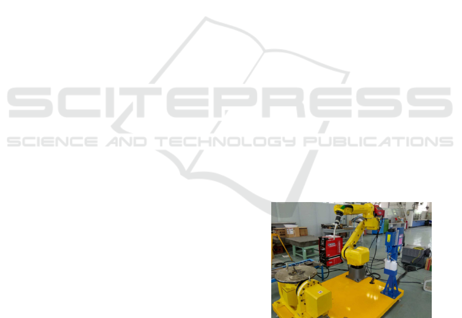
Figure 1.Robotic arc welding system.
Robotic arc welding system is mainly composed of
FANUC M-20i six joint robot, 500kg of two-axis
displacement machine, Lincoln R500 arc-welding
machine, STT advanced welding process module,
automatic wire feeding machine, ABIROB A500 air-
cooled welding torch and Torch Clean Station
cleaning equipmentas shown in Figure 1.At the same
time, it is equipped with J511 welding arc tracking
software, J536 starting point seeking software, J532
multi-layer welding software.
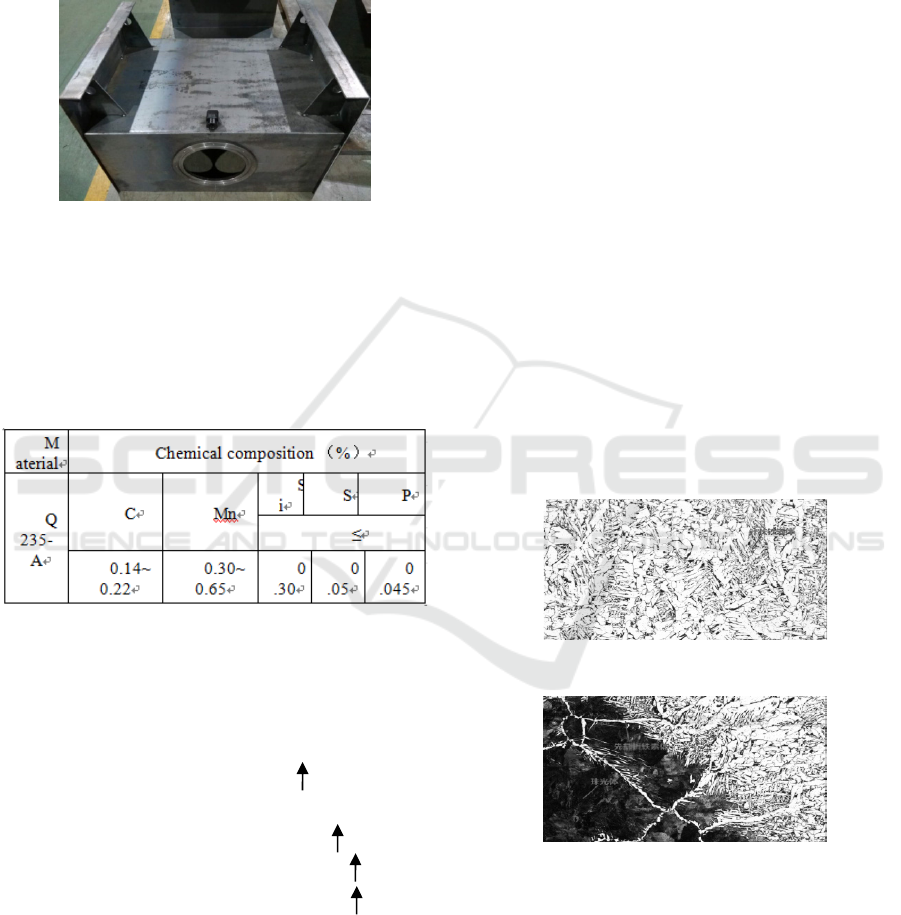
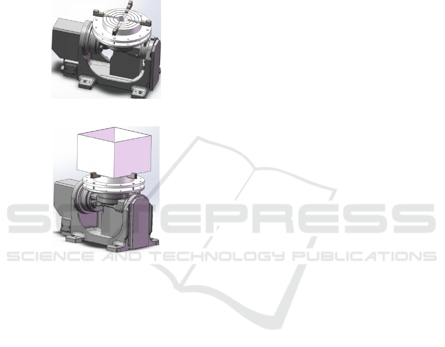
2.2 The Welding Object
Figure2. Hydraulic oil tank.
The welding object is a type of tire vulcanizing
machine oil tank and its size is
1000mm×500mm×500mm as shown in Figure 2.
The material is Q235-A steel, its chemical
composition is shown in Table 1.
Table 1:The chemical composition of welding material.
The metallurgical reaction of welding material in
welding process is closely related to the formation of
welding porosity[1].When the carbon content in the
liquid weld is high and the deoxidation is deficient,
there are more FeO in the molten pool.When the
molten pool temperature drops, the following
reaction will occur[2]:
[ C ]+[ O ]= CO
[ FeO ]+[ C ]=[ Fe ]+CO
[ MnO ]+[ C ]=[ Mn ]+CO
[ SiO2 ]+2 [ C ]=[ SiO ]+CO
If the molten pool has started to crystallize, then
CO will be unable to escape and produce a CO
porosity. The higher the carbon content of the
welding material itself, the more likely it is to
produce a CO gas, thus forming a porosity.
The Si and Mn in the welding materials are
deoxidized elements which can effectively inhibit
the production of CO gases.But the contents of Si
and Mn in parent material are usually not
high.Therefore, the wire with high content of Si and
Mn, such as H08Mn2Si wire, can effectively
suppress the keyhole-induced porosity
[3].
3 EXPERIMENTAL STUDY ON
ROBOT WELDING PROCESS
The welding process test involves the influence of
parameters such as welding voltage, current,
welding speed, shielding gas (type and flow rate) on
the quality of welding seam. Huang Jiaqing[4], from
zhong che zhu zhou electric locomotive co., LTD,
has studied the welding process of the locomotive
bogie hollow shaft robot. The experimental results
show that it is better to use 80% Ar + 20% CO
2
mixture protective gas than the CO
2
protective gas in
welding process and the microstructure of the
welding joint consists of acicular ferrite as shown in
Figure 3.The microstructure of the overheat zone in
the thermal area of welding is obviously grown as
shown in Figure 4, and its tissue is consists of pre-
eutectoid ferrite, pearlite and a small number of
bainite.
Figure 3 The microstructure of weld seam[4].
Figure 4.The microstructure of the fusion area[4].
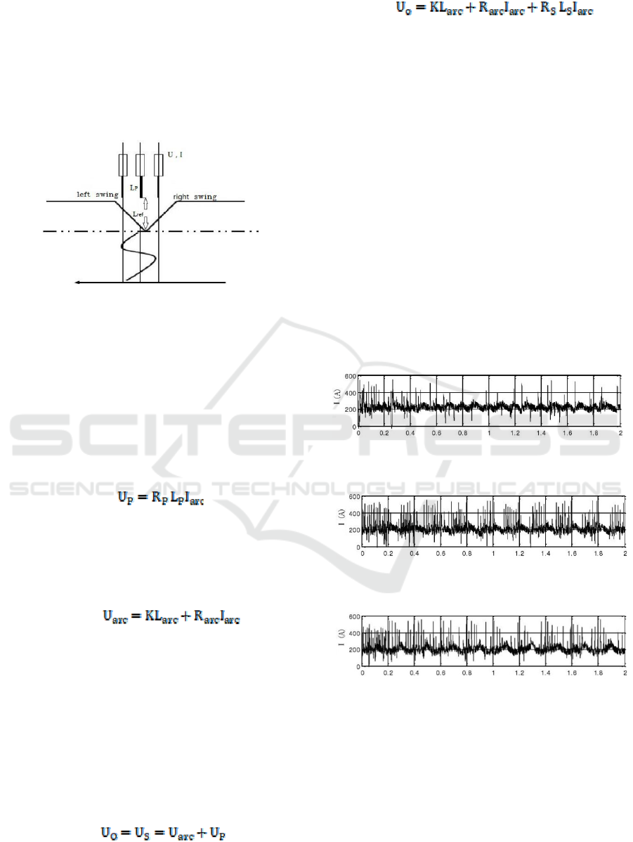
During the early stage of the welding process
test, the welding voltage, current, welding speed,
protective gas (type and velocity), arc starting and
stopping control parameters did not match properly,
which lead to welding quality is not ideal as shown
in Figures 5 and 6.The quality of the start and end
point of arc welding is poor, the surface of welding
seam is discontinuous and raised serious.
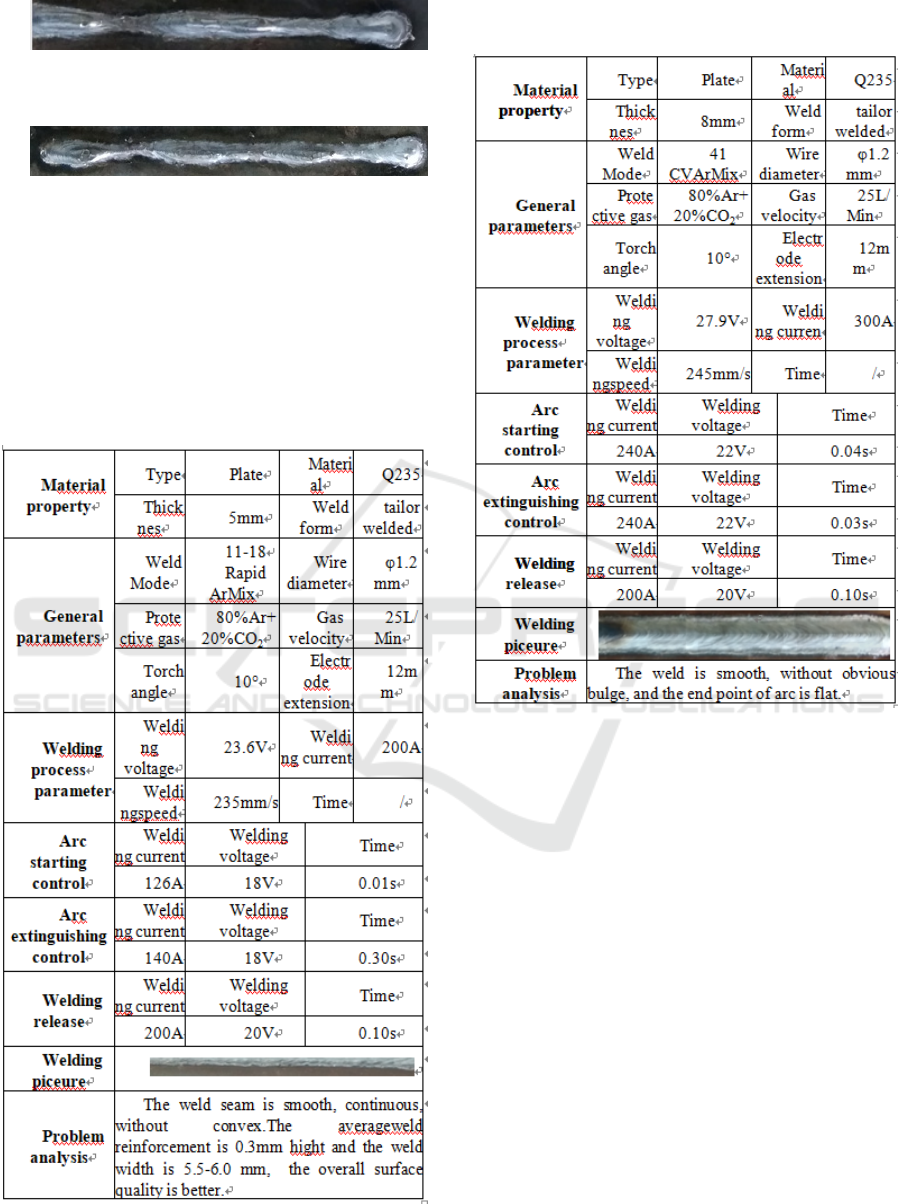
Figure 5.The weld molding under the immature process
parameter (1).
Figure 6.The weld molding under the immature process
parameter (2).
After a lot of process experiments and refer to the
relevant welding literature, the author finally
determined the better welding parameters of 5mm
and 8mm these two kinds of common plate thick
fuel tank as shown in table 2 and 3.
Table2: Welding process parameters of 5mm thick Q235
carbon steel plate.
Table3: Welding process parameters of 8mm thick Q235
carbon steel plate.
4 THE RESEARCH ON SEAM
TRACKING TECHNOLOGY
Because the processing error of the tank plate is
larger(about 1~3mm), the source of the error mainly
includes the followings: (1) The dimensional error
and deformation caused by the shearing process of
plate shearing machine;(2) The bending process
would produce dimensional error. Beside, because
the welding process would produce thermal
deformation, it causes current teaching programming
can not meet the requirements of real-time seam
tracking. Therefore, seam tracking technology
should be introduced.
In the research of seam tracking technology, Sun
Li, Lin Tao and others from Shanghai Jiao Tong
University[5], Gao Xiangdong, Ding Dukun and
others from Guangdong University of
Technology[6], have studied a seam tracking
technique based on machine vision, Zhang
Wenzeng, Chen Qiang and others from Tsinghua
University[7], Sun Mei,Du Jun and others from
Nantong University[8], have studied the trajectory
tracking technology of welding robot based on 3D
stereovision. Although the above scholars have
made many achievements, we consider the cost of
the program and the ease of implementation of the
technology, this article studied welding seam
tracking technology based on arc sensor( The
principle is shown in Figure 7).
Figure 7.Working principle of arc sensor.
By establishing a simplified numerical model
between the output voltage Uo and the arc length
Larc and the corresponding current Iarc, and
compare the current Iarc at different distances with
the reference current Iref of the system, thus
realizing the position tracking of the welding seam
in the periodic swing welding process.
Among them, the voltage drop of electrode
extension is:
(1)
In the formula, RP is resistance per unit electrode
extension. Lp for electrode extension.
The relation between the voltage Uarc and the
current Iarc and the arc length Larc is:
(2)
In the formula, K is a unit of arc long voltage
drop, L
arc
is arc length, and R
arc
is arc equivalent
resistance.
In the process of welding, the supplyenergy
between welding power and welding arc should be
balanced[9]. That is to say, the output voltage of the
welder U
O
is equal to the arc load voltage U
S
, while
the arc load voltage U
S
includes the arc voltage U
arc
and the voltage drop of electrode extension U
P
as
follows:
(3)
Comprehensive formula (1), (2), (3) available
(4)
In the welding process, the distance from the
welding wire to the bottom of the V type weld is set
to the reference distance L
ref.
According to the
formula (4), we can see the value of the
corresponding current at this time, and set it as the
reference current I
ref
in the system. In welding
process, the distance of the wire from the bottom of
v-shaped weld will change in real time by setting the
welding torch to swing welding. At this point, the
currentvalue of the arc sensor is I
arc
as shown in
Figure 8-10.Comparing with the reference current
I
ref
, when the welding trajectory is located in the
center of the weld as shown in Figure 8, I
arc
=I
ref
, the
current waveform is symmetrical, and the torch is
advancing along the current weld trajectory; When
the welding seam trajectory deviate left or right of
the weld seam as shown Figure 9 and 10, I
arc
≠I
ref
.At
this time, the position of welding gun is modified
continuously during the welding process, to searched
the position of I
arc
= I
ref,
which can achieve the
purpose of real-time weld tracking.
Figure 8.Current waveform diagram when the welding
trajectory is located in the center of the weld
[10].
Figure 9.Current waveform diagram when the welding
trajectory deviate left of the weld seam [10].
Figure 10.Current waveform diagram when the welding
trajectory deviate right of the weld seam [10].
5 FLEXIBLE FIXTURE DESIGN
At present, most hydraulic stations are designed and
manufactured in non-standard format, which results
in various types and sizes of the fuel tanks.
Furthermore, the plates have a certain size error in
cutting and bending process. Therefore, it is
necessary to have some flexibility for the
corresponding fixture clamping device, which can be
compatible with different types of fuel tank for
quick loading and positioning. Aiming at the above
problems, this paper designs a flexible fuel tank
fixture based on pneumatic four-jaw as shown in
figure 11 and 12.
Figure 11.3D design of fuel tank fixture (1).
Figure 12.3D design of fuel tank fixture (2).
6 CONCLUSION AND PROSPECT
(1) Using robot to weld fuel tanks at the production
site, the speed can be as high as 245mm/s. With
special fixture, it can realize batch welding, high
welding efficiency and good welding quality. The
workload of a robot is equivalent to 3 to 4 ordinary
welders. Besides, in the case of reasonable welding
process, the welding qualification rate is high, the
rework quantity is small, the labor cost is greatly
saved, and the economic benefit is significant.
(2) In the aspect of study on seam tracking
technique,the research of this paper only based on
arc sensing at the present stage. Tracking stability
and compatibility is relatively poor and we are going
to conduct the study of weld tracking technology
based on machine vision.
(3) At the present stage, this paper just studied
welding process and fixture design of fuel tank.The
follow-up will be carried out through the test of
welding quality research, such as ultrasonic testing,
tensile and bending, metallographic experiment,
focusing on analysis of welding seam inside the
porosity, crack defects, and then optimize the
welding process.
ACKNOWLEDGEMENTS
This paper was financially supported by the 2015
Guangdong Science and Technology Project
(No.2015B010918002), 2016 Guangzhou Science
and Technology Project (No.201604016115) and
2017 Sinomach Intelligence Technology Co., Ltd
Fund Project (No.62300002).
REFERENCES
1. Wang Lifeng,Liu Fengde,Liu Weina. Study on
control method of porosity in laser-arc hybrid
welding for high nitrogen steel[J]. Journal of
Mechanical Engineering , 2016,52(20):51-59.
2. Lin Rui.Causes and control measures of welding
porosity in long distance pipeline[J]. Petro-Chemical
Equipment, 2016,19(5):75-77.
3. Chen Wuzhu, Quality control of laser welding and
cutting[M] ,China machine Press, 2010.
4. Huang Jiaqing, Improvement of welding process for
hollow shaft robot[J]. Welding Technology,
2016:601-605.
5. Sun Wei. Study on the seam tracking control system
based on CCD visual sensor[D].Shanghai Jiao Tong
University,2008.
6. Gao Xiangdong,Ding Dukun,Zhao Chuanmin,et
al..Seam tracking technology based on machine
vision[J]. China welding, 2006 (2):19-23.
7. ZhangWenzheng,Chenqiang,Dudong,Sunzhenguo,et
al.. 3-D vision-based trajectory tracking of welding
robots[J]. Journal of Tsinghua University (Science
and Technology),2007, 47 (8):1270-1273.
8. [8]Sun Mei.Research on seam recognition and
tracking technology of mobile welding robot based
on stereo vision[D]. Nantong University, 2013.
9. Liuyue,Liunian, et al.. Research on seam tracking
system of arc welding robot based on sine pendulum
welding. Machinery & Electronics, 2016,34(10): 76-
80.
10. Liunian, et al.. Research and implementation of
seam tracking system for arc welding robot[D].
Harbin Institute of Technology, 2015.
