
An Automation Positioning Measurement System Based on
Multi-measurement Equipment
Hongli He
1
, Jie Zhang
1,2
, Quanbo Ge and Zhongcheng Ma
3
1
Institute of testing, Chinese Flight Test Establishment, Xi'an, China
2
School of Aviation, Beijing University of Areonautics and Astronautics, Beijing, China
3
School of Automation, Hangzhou Dianzi University, Hangzhou, China
Keywords: Three-dimensional model, Automation measurement, Simulation, Flight test.
Abstract: According to the requirement of flight test, The high precision Automation positioning measurement system
is designed and implemented for obtaining three-dimensional points, lines or polygons of measured object.
The system can be satisfied with the needs of future weapons development. The system functions include
simulation, online measurement, fast processing, real-time monitoring etc. The system structures,
framework and composition are given. The key technical problems are analyzed in order to know of the
system feasibility. A feasible platform are set up by total station instrument, light pen, image measuring
system equipment in the laboratory. The interface performance, real time guide, coordinate transforming,
adjustment of observation are verified. The algorithm accuracy is verified. The system construction thought
is overall being planned. The system will effectively boost the development in flight test, It is very
important to improve testing precision, speed or saving manpower and material resources.
1 INTRODUCTION
Space positioning measurement for Flight test is
surveying the aviation aircraft position and other
parameters of the target in the real test environment,
which mainly is used for the establishment of Spatial
reference Information and the value transfer,
installation and calibration for weapons, the plane
deformation test and three-dimensional
model[1,2].The improving of the aviation weapon
performance put forward higher requirements for
measurement. Measurement object is becoming
more and more complex, it is not only to measure
the position of aircraft and weapons, but also to
measure the relationship between weapons and
aircraft. The accuracy requirements for attitude
angle arc seconds, positioning requirements are
millimeter. The measurement tests get more and
more. The measurement items are more than one
type measured with high frequency which measure
hundreds of sorties every year; the original static
measurement is converted for static and dynamic
binding; The automation technology research must
be conducted in order to improve the accuracy and
reliability and the test efficiency[3].
At present, digitalization and detection
technology are becoming more and more mature.
Model-based detection technology has become the
main detection method for engineering,and Model-
based detection technology effectively improve the
detection capability and efficiency[4].
Model-Based Systems Engineering is regarded
as the "revolution" of system engineering, "the
future of system engineering ","transformation of
system engineering" and so on. China Aviation
Industry Group has also carried out related research
and application[5,6].
According to the requirement of flight test, the
high precision automation engineering positioning
measurement system for flight test is designed and
implemented for obtaining 3D points, lines or
polygons integration of measured object in greater
scope. The system should be satisfied with the needs
of future weapons development. The system
functions include simulation ,online measurement,
fast processing, real-time monitoring etc. The
system can realize the plane model building,
installation process online test for weapon system on
the aircraft ,the complex body positioning
monitoring, monitoring of the test site ,which can
provide the basis for on-the-spot decisions.
This subject provides new methods and new
ideas for online monitoring ,provides technical
support for the research of distributed large-scale
measurement, and also provides online error
correction of industrial robots, online space
positioning and reverse engineering, which is
widely used for flight test.
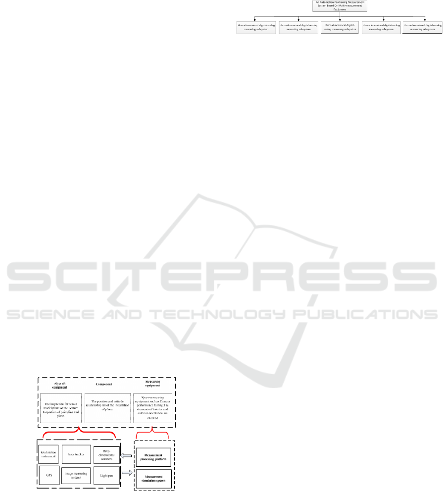
2 THE SYSTEM FRAMEWORK
2.1 Basic Framework
According to the requirement of flight test, using the
advanced digital measurement equipment such as
total station instrument, light pen, image measuring
system equipment ,3D scanners, GPS, laser tracker,
etc. based on 3D digital-analog measuring system
composed of a set of automation measurement
system, through the computer and automatic control
technology to achieve integration measurement
7
.
Through offline programming device layout and
mission planning system after the completion of
online testing in the field of data processing,
shortening the processing cycle, improves the
effectiveness and accuracy of the measured data .In
the measurement platform building process, we
should fully consider the system's advanced nature
that system construction should not only have data
processing and control functions, but to be able to
optimize the layout of measurement equipment, In
the measurement task trace route planning, ensure
the accuracy of automated measurement. The
framework of the system is shown in figure 1.
Figure 1: System frame of multi-measurement equipment
diagram.
2.2 System Components
Figure 2: An Automation Positioning Measurement
System composition.
According to the characteristics of flight test,
automation high-precision measurement system are
set up, which can achieve fast automated collection
for feature point, line, polygon data, recording,
computing and other functions. Automation
measurement system is mainly composed of the
following parts: accurate point measurement
subsystem, image measurement subsystem, three-
dimensional digital-analog measuring subsystem,
measurement and control center subsystem,
measurement simulation subsystem. The system
composition is shown in figure 2.System equipment
composition is shown in figure 3.In which precise
point measurement subsystems, 3D modeling
subsystems, image measurement subsystem achieve
information collection and access. measurement and
control system is the core of the whole system that is
responsible for data processing, control, guidance,
analysis, display function; measurement simulation
mainly completes the measurement equipment
layout, composition and measuring path planning,
which is key to optimize the allocation of system,
but also automatic measurement of foundation. The
specific composition is as follows:
1) Accurate point measurement subsystem:
which is made up of the total station, light pen,
Laser tracker and other equipment, which can obtain
3d measurement information about the main point
features.
2) Image measurement subsystem: which is
composed of camera, lens, analytical software, The
key point coordinates were obtained using digital
close-range photogram metry principle, The static
or dynamic measuring process target point
coordinates can be given through calculating.
3) Three-dimensional digital-analog measuring
subsystem: including 3D scanner, hand held scanner,
model building tools, etc., is mainly used for model
construction or the measurement about Surface
target and the attitude datas of the object.
4) Measurement and control center subsystem:
mainly achieve the system camera, 3D laser scanner
and total station and other equipment background
operation control and real time information
collection, guide transmitted, the processing,
evaluation, display, with image processing, data
processing, and analytical parameters adjustment
calculation and other functions.
5) Measurement simulation subsystem: the
simulation model is established according to the
measurement task requirements and site
environmental knowledge, through simulation and
calculation on measurement characteristics, through
the simulation is given a specific task in measuring
device configuration, layout and measurement task
planning is key to optimal allocation of system. The
main task is to prepare for the simulation of the
field, the equipment layout, equipment interference,
measurement of the trajectory of the simulation, the
test quantity schemes and plans to confirm.
Figure 3: System equipment composition.
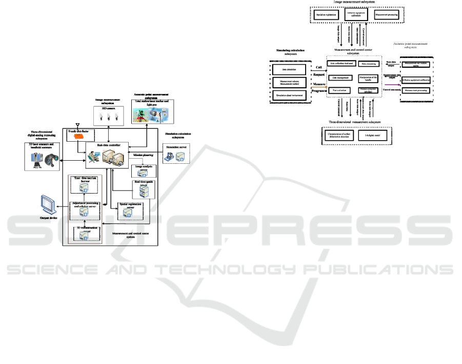
2.3 Second Section
For a test, it is necessary to carry out automation
measurement, first of all, according to the
requirements of the task We measure the field
simulation environment and get the measurement
plan. This subsystem transfers the measurements
related to the planning, equipment status information
to the control center, which is based on the original
digital to analog information into the coordinate
conversion, converts data into the value of the
respective equipment coordinate measuring system
and controls the equipment in accordance with the
requirements for automatic measurement. Other
precise measuring system, image measuring system,
3D modeling system are based on the control center
issued the control instructions ,then take the
respective measurement data back (transfer) to the
monitoring and control center for the integrated
treatment, carrying out after the process is
completed testing and evaluation, and save all the
measured data, the data results in accordance with
the statements of the model output; model formation
through the model viewer access. All measurements
according to the measurement plan under control of
Control Center automatic completion of the
measurement. According to the above planning, the
information exchange between the system and the
measurement system is given as shown in figure4.
Figure 4: Information exchange.
2.4 Software Framework
The system software is based on operating software,
supporting software.
Different kinds of measuring instruments often
use different communication interface standards,
which makes data communication and integration
difficult. For point, line and polygons Object,
different measuring devices are adopted, Unified
standard interface is designed to control all data in
the same control center , Three dimensional CAD
software (such as CATIA and UG) has been
developed. Based on the unified measurement
kernel, information such as geometric information,
dimensional tolerance, inspection plan, simulation
and measurement results are shared seamlessly
between the same or different platforms. All data are
managed to achieve information integration and
closed loop feedback[4,8]. Application software is
the key to intelligent measurement of the system. Its
composition and functions are as follows.
The application software contains the following
functions:
1) The collected data is mainly from the total
station ,laser tracker and three-dimensional scanning
instrument, some data is from the manual input
parameter information or the model data
information. The data and images of all the
measuring devices can be unified into the network
interface for data transmission, which is in order to

send data efficiently . the hardware interface must
be extensible.
2) Mage data, model construction can be
processed in the data processing center and the data
of multi - measuring equipment can be combined
adjustment. many kinds of data from various
measurement devices can be processed, including
original measured data, the data generated to show
on the device and the data to guide.
3) It is mainly used for the preparation of the
measurement task, Simulated measurement site, The
purpose of simulation is to plan the layout of
equipment, to know interact with each other and
gain the planed path.
4) The software are decomposed and analyzed
to the task. The software can be automatically
measured according to the data of the model
database, and the various instructions can be
manipulated.
5) The Man-machine interface is mainly
convenient for information interaction. It is
responsible for the display of plane and table
information on the display console the software
receives various intervention commands and manual
input data, and can read the three-dimensional
model.
3 KEY TECHNOLOGIES
3.1 The Reasonable Design,
Arrangement and Measurement of
the Control Standard
A comprehensive measurement system composed of
multi measurement equipment to obtain high
accuracy of the measurement results, firstly we must
determine the structure of observation and how to
layout, according to the measurement conditions and
the characteristics. In design process, a variety of
measurement equipment is needed to identify a
common characteristics of the measurement symbols,
we must think of the size scale of the measurement
object, the structure characteristics of the mark
points. According to the task of designing a common
identity, public signs are shown in Figure 5. Each
different mark represents a different point, and
different measuring equipment must identify the
center of each mark, Only in this way the data from
multi - measurement can be spliced or be fused.
Figure 5: Public sign.
To improve the measurement accuracy, it is
necessary to obtain diversity of observation data in
the layout process. Diversity observation data will
be the basis for an accurate adjustment model. We
need to consider measurement datas of blind
distribution, spatial distribution of the optical unit
can be used, The space of light coverage and the
light source arrangement of Optical measurement
system should be considered. when above all
problem are solved Enter the actual measurement.
3.2 Based on the Model of Automation
Measurement Process Design
Automation measurement process model is
designed based on digital three-dimensional
simulation model[9,10], The task demand is
analyzed and simulated. measurement instruction is
generated ,according to the relevant test
requirements, The selection, combination and layout
of the measurement equipment are carried out by
simulation measurement, according to the site
environment; Based on the integrated control and
automatic measurement of the measured plan
generated by the simulation, All measurement data
are collected and calculated in the measurement and
control center, Building a unified coordinate system
for data solver to complete the on-line analysis.
Finally, the result of measurement is given.
Automated measurement procedures are as follows.
Figure 6: Based on the model of automation measurement
process design.
3.3 Measurement Simulation
Measurement simulation is the most important
condition to realize Automation measurement, and
establishing a reasonable measuring field model is
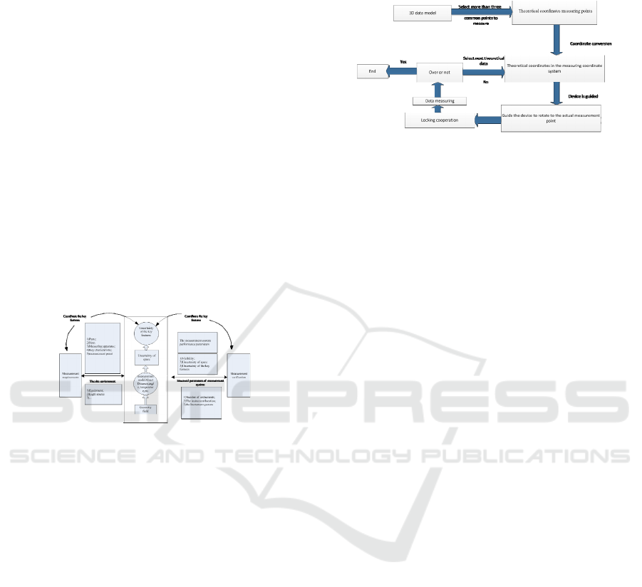
the base and key of the measurement planning and
system optimization in the field of complex aviation
experiment[11,12]. Overall, the field measurement
model should establish in accordance with the
measurement task requirements and site
environment model, which should include work
space, spare parts, obstacles, measurement,
measuring instruments, environmental factors of
measuring space etc. measurement system combined
with a different layout or configuration scheme, the
simulation will form different field measurement
results, the performance parameters of the
measurement system can be obtained before the
implementation of the actual measurement through
simulation. which can be in the evaluation of the
performance parameters of the measurement system
and the optimization of structural parameters to
verify the measurement field model and testing
requirements match, in the simulation process focus
on visibility and accuracy characteristics. The
simulation process is shown in figure 7.
Figure 7: Measurement simulation processn.
3.4 Automatic Measurement Process
Sample
The equipment used for automatic measurement
includes the tracking devices (tracker, total station),
and automatic aiming measurement is realized by
adopting the mode of coordinate value conversion -
equipment automatic driving - automatic point
finding -- Data collection. First , the theoretical
position of each measuring points under the design
coordinate system is obtained based on based on 3D
model, the conversion relationship between the
design coordinate system and the measurement
coordinate system is calculated, the theoretical
coordinate values of each measuring point under the
measurement coordinate system under the current
actual state are obtained, the measuring equipment is
automatically positioned near the measuring point to
be acquired through a program control, so that the
tracker automatically and accurately find a target
bull's-eye ball, complete the measurement. then
enter the next desired point of the search and
measurement. The process is shown in figure8.
Figure 8: Automatic measurement sample.
4 APPLICATION VERIFICATION
Using a combination of total station instrument,
lightpen, image measuring system equipment into an
integrated measurement platform. Through
measurement platform, Interface interoperability,
real-time guidance, coordinate transformation and
adjustment function can be verified. we can use the
software to develop stable controling equipment for
measuring, integrate precision accuracy is better
than a separate device; measurement range is
expanded,1+1>2 function can be realized. At the
same time, in the process of testing a number of
models, we test the combination of automated
measurement mode, achieve an online measurement;
improve the efficiency and reliability of
measurement.
5 CONCLUSIONS
Using total station instrument, light pen, image
measuring system can be composed of Automation
engineering measurement system; after the
completion of the Automation measurement system
can achieve routine tasks online measurement and
improve measurement speed and work efficiency.
To achieve the Automation test target requires
overall planning, the gradual implementation of the
construction line up at the facets, we are building
Automation test work progresses follow this idea.
The system will give a strong boost to the
development of flight test of Automation testing
technology, improving test accuracy and
measurement speed, saving manpower, material
resources.

REFERENCES
1. Tingwu, Y., Zhengzhong Z., 2014. Optical-Electronic
Measurement Theory and Methods in Flight
Test,National Defence Industry Press,Beijing.
2. Puzhou, R., Hongli H., 2012. Application of
photoelectric test technology in flight test,2012
western conference paper on photonics,Xi’an.
3. Zhou, Z, Q., 2010. Flight test project,Aeronautical
Industry Press,Beijing.
4. Zhang, L., Shan CL., 2015. Inpection Technology of
Aero-Engine Parts Based on MDB
Model,Measurement and control technology.
5. Shan CL., Yang HY., 2014. Research on Digital
Inspection Technology of Profile,Aviation Precision
Manufacturing Technology.
6. Chen, JT., 2016. The basic principle of system -
Engine based on Model,Aerospace China.
7. Maxham, D., 2010. Practical Means of VEC Applied
in Calibration of Large-Scale Machine
Tool,Aeronautical Manufacturing Technology.
8. Luo, F., Zhou, W. ,Y., 2014. Motion Planning and
Precision Controlling in Component Automatic
Butt,Aeronautical Manufacturing Technology.
9. Li, G., L., Meng, Y., M., 2015. Assembly Measure
Process Planning based on the 3D Assembly Process
Model,Aeronautical Manufacturing Technology.
10. Jun, X., P., Yao, 2005. Study on a three-dimensional
digital assembly process planning system,Journal of
Harbin Institute of Technology.
11. Zhu, X., S., Zheng, L., Y., 2005. Multiple-objective
optimization algorithm based on key assembly
characteristics to posture best fit for large component
assembly,Acta Aeronautica et Astronautica Sinica.
12. Zheng, L., Y., Shao, J., 2012. Large-Scale
Measurement Software Integrated in
CATIA,Aeronautical Manufacturing Technology.
