
Experimental Study of Fiber Reinforced Concrete Based on Freeze-
Thaw Environment
Baidong Zhao
1
, Zhiyou Sun
1
and Shun Wang
1
1
School of Architectural and Civil Engineering, Shenyang University, Shenyang, 110044, China
Keywords: The freeze-thaw cycle; fibrous concrete; water cement ratio; concrete durability.
Abstract: The ordinary concrete has a poor frost resistance. It is often destroyed in the practice of low temperature
engineering. By means of investigating the influence of different fiber on the durability of concrete, based
on different number of freeze-thaw test block, combined with the concrete water-cement ratio, also the
relative dynamic elastic modulus, mass lose rate and the relative compressive strength. It is concluded that
when the parameter of the C40 concrete fiber is about 10%, it has the most engineering significance.
1 INTRODUCTION
In the engineering projects in recent decades, large
volume of concrete has been widely used, including
house building, tunnel construction, road and bridge
construction, etc.. With basalt as impact factor, the
reference [1] researches the properties of concrete
under various environmental conditions. Scholars
Mu Ru [2] et al. studied the durability of concrete by
different freeze-thaw tests and analyzed the
mechanism of freeze-thaw test in detail. Scholars
Liu Weidong [3], et al. studied the impact of fiber
content upon concrete damage and deterioration by
building the freeze-thaw cycle damage constitutive
relationship of concrete. Scholars Zhou Zhiyun [4]
et al. reflect the frost resistance of concrete
indirectly by its dynamic elastic modulus. Scholars
Wei Qiang [5] et al. analyzed the damage of freeze-
thaw environment upon concrete more visually by
magnifying concrete test block residue after freeze-
thaw with Scanning Electron Microscope (SEM).
Scholars Chen Sijia [6] et al. studied the influence of
different mix ratios of reinforced concrete upon frost
resistance of structure under freeze-thaw
environment.
Most buildings are exposed to natural
environment and contact with the atmosphere.
Rainwater, sandstorm, etc. in the atmosphere causes
irreversible damage to buildings. The difference of
climates and geographical locations directly
influences the durability difference of large-volume
concrete structure, and however, frost is the main
factor in north area. Freeze-thaw damage are caused
to concrete structure in cold north area, thus the
large-volume concrete has potential safety hazard
and even is damaged before the end of its service
life, which causes directly economic loss to the
country. In the Code
[8]
, the environment is divided
into five types, including freeze-thaw environment.
This shows that the influence of freeze-thaw
environment upon the construction industry is
enormous. Shenyang is in North China and in almost
half a year its temperature is below zero, and thus,
the requirement for the frost resistance of
construction materials is more rigorous. The scheme
taken in this test is adding man-made mineral fiber
in the aggregates of concrete test block to research
the intensity change of concrete under freeze-thaw
environment and reflect the durability of concrete
structure under lower temperature in actual projects.
2 FREEZE-THAW TEST AND
TEST METHOD
2.1 Freeze-thaw Test
The two freeze-thaw test methods often used are
rapid freeze-thaw technique, one is air freeze-thaw
technique, and the other is water freeze-thaw

technique. This test used water freeze-thaw
technique. The freeze-thaw temperature in the test is
-20℃-20℃, and the freeze-thaw time is two hours
with an interval of one hour. The test instruments
used include JCD freeze-thaw machine, TM-II
dynamic elastic modulus measurement instrument,
electronic scale, etc. the test block was freeze-
thawed for 200 times and test data was acquired
every 40 times for comparison and analysis. Total 6
groups of test blocks were prepared (1 group for
backup), each group had 6*4 standard concrete test
blocks, 144 in total. Before preparation of test
blocks, inspections shall be done to check if all
materials conform to the test standards, if cements
are hydrated, and if gravel particle diameter
conforms to the standard, etc.
What needs to be noted is that, because it is a
water freeze-thaw cycle test, to make sure the test
blocks are fully immerged in water, the influence of
air upon the freeze-thaw test was avoided by
immerging concrete test blocks 3mm under the
water before the test.
2.2 Test Material and Model
Preparation
Water used in this test was the domestic drinking
water in Shenyang, 425# ordinary Portland cement
was used, with the density of 3.12g/cm3. The
particle size of the gravel used was 7-18mm, and the
medium coarse river sand and ordinary man-made
mineral fiber were used. According to the Code [7],
the concrete test blocks prepared for this test were
150mm*150mm*150mm cubic blocks and
100mm*100mm*400mm cuboid blocks. The
designed strength of ordinary concrete was C40.
Table 1 shows the mix ratios of concrete test blocks
with different proportions of fiber contents and
corresponding slump degrees. The concrete test
blocks were cured under standard conditions for 28d
in standard environment.
2.3 Mix Ratio Design of Test Block
Whether the design of mix ratio is reasonable or not
directly affects the result of test. The mix ratio
should be verified for reasonablity repeatedly in
strict accordance with the steps of mix design. The
mix ratio design of this test is based on different
fiber contents, the mass of each aggregate mixing
content in 1 m3 of concrete is 2450kg, see Table 1
for details. According to the steps of mix design for
ordinary concrete, the test designed and determined
two types of the concrete water-cement ratios:
W/C=0.46 and 0.51
3 RELATIVE DYNAMIC
ELASTIC MODULUS OF
CONCRETE
The performance of concrete after being freeze-
thawed is usually evaluated by two standards in the
Concrete Code [7]. The first method is to measure
with relative dynamic elastic modulus, only when
the dynamic elastic modulus ranges from 60% to
100%, it is deemed that the concrete has not been
destroyed in the freeze-thaw damage environment.
The second standard is to take whether the mass loss
rate of concrete test block after the freeze-thaw
cycles exceed 5% as a measure to evaluate the
concrete. Due to the loss and crack of concrete after
freezing and thawing, the concrete may has water in
some parts. Such factors may cause errors in the
mass of concrete. Therefore, sometimes the mass
loss ratio may increase on the contrary, which may
influence the test result. Considering such factors,
the water on concrete should be removed when
acquiring the concrete mass data after freezing and
thawing. In this test, the test blocks were
preliminarily treated with fan and absorbent paper,
which was weighed, and analyses were made by
combining relative dynamic elastic modulus data of
concrete. From Table 2, it can been found that the
compressive strength of concrete decreases as
freeze-thaw cycles increase, and comparing ordinary
concrete with the test blocks with different fiber
contents, the concrete strength is damaged more
obviously as the freeze-thaw cycles increase. As
fiber content in the concrete increases, the
compressive strength of concrete under the same low
temperature environment is better, and test blocks
with approximately 10% fiber content are more
suitable for projects. As freeze-thaw cycles increase,
especially after 120 cycles, whether the concrete
contains fiber or not, the concrete strength decreases
to 50% of that under standard curing environment,
and after freeze-thaw cycles increase to above 160,
the strength of test block will be fluctuating at 25%
of that under standard curing environment. This
proves that after approximately 120 freeze-thaws,
the concrete has basically lost its strength, and
freeze-thaw is the most important factor that
damages concrete strength.
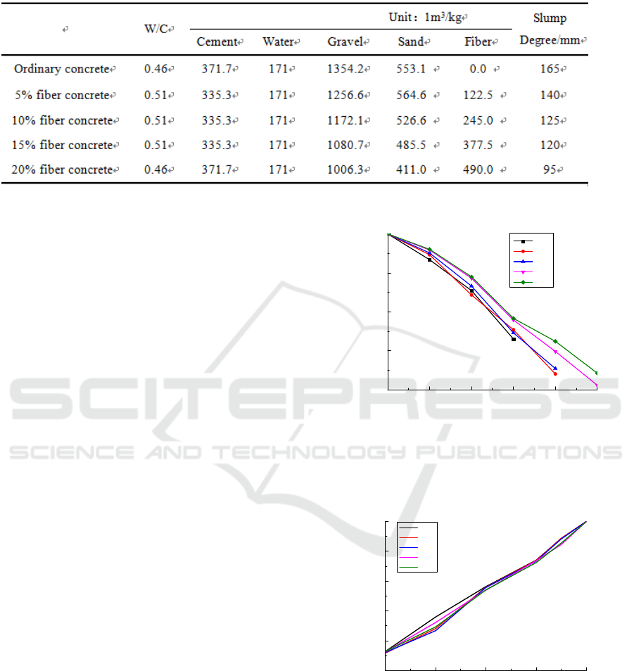
Table 1:Concrete mix ratios with different fiber contents.
From the data in Table 2 and curve in Figure 1 it can
be found that the relative modulus of each fiber test
block is above 60% when freeze-thaw cycle ranges
from 0 to 120, while the relative modulus of
ordinary test block has already decreased to below
60% after 160 or more freeze-thaw cycles and that
of the 5% and 10% fiber test blocks has also
dropped to below 60% after 160 freeze-thaw cycles.
Only the relative dynamic elastic modulus of 5%
and 10% fiber test blocks is above but close to 60%
after 200 freeze-thaw cycles. This shows that
concrete durability can be improved by fiber, but
after the concrete is freeze-thawed for enough times,
its durability can still be damaged. From the entire
curve in Figure 1, it can be found that the freeze-
thaw cycle and relative dynamic elastic modulus of
concrete have a linear curve relation, namely that the
relative modulus of concrete decreases as concrete
freeze-thaw cycles increase.
In Figure 1, the change of the relative modulus of
fiber test blocks tends to slow down after 120 freeze-
thaw cycles. The probable reason is that when the
freezing and thawing just starts, the initial defects of
the test blocks and materials are fully developed in
the freezing environment, thus leading to the quick
decrease of relative modulus of concrete. When the
defects in the concrete material develops to a certain
extent, the change of relative dynamic elastic
modulus of concrete slows down as the curve of
freeze-thaw count goes down.
0 40 80 120 160 200
60
70
80
90
100
relative dynamic modulus of elasticity/%
freeze-thaw cycles/n
0%
5%
10%
15%
20%
Figure 1:Curve of relation between freeze-thaw cycle
and relative dynamic elastic modulus of concrete with
different fiber contents.
60 70 80 90 100
0
20
40
60
80
100
residual compressive strength/%
relative dynamic modulus of elasticity/%
0%
5%
10%
15%
20%
Figure 2 : Line diagram of relative dynamic elastic
modulus and residual compressive strength of concrete
with different fiber contents.

Table 2:Relative dynamic elastic modulus, mass loss rate and compressive strength of different concretes after freezing
and thawing.
Freez
e-thaw
count
Relative
dynamic elastic
modulus/(%)
Compressi
ve strength
before freeze
t
h
aw/
MP
a
Compressi
ve strength
after freeze
t
h
aw/
MP
a
Relative
compressive
strength/(%)
Mass loss
rate/
(
%
)
Ordinary
concrete
0
1
00.000%
4
0.000
4
0.000
/
/
4
0
93.37
2
%
4
0.000
3
4
.863
87.
1
58%
0.9
24
%
80
85.
4
63%
4
0.000
2
5.6
22
6
4
.055%
0.389%
12
0
73.037%
4
0.0
00
1
7.
4
78
4
3.695%
2
.753%
1
60
/
4
0.000
1
0.390
2
5.975%
/
2
00
/
4
0.000
4
.65
111
.6
2
8%
/
5% fiber
concrete
0
1
00.000%
4
6.000
4
6.000
/
/
4
0
9
4
.6
4
7%
4
6.000
4
0.6
1
9
88.30
2
%
0.
2
85%
80
8
4
.33
2
%
4
6.000
33.03
1
7
1
.807%
1
.
2
8
2
%
12
0
75.
421
%
4
6.000
2
0.3
1
6
44
.
1
65%
3.
11
5%
1
60
6
4
.06
1
%
4
6.000
12
.03
42
6.
1
6
1
%
4
.
1
8
4
%
2
00
/
4
6.000
5.
1
75
11
.
2
50%
/
10% fiber
concrete
0
1
00.000%
4
9.000
4
9.000
/
/
4
0
95.
11
3%
4
9.000
4
3.0
21
87.798%
0.
42
7%
80
86.597%
4
9.000
35.878
73.
22
0%
0.863%
12
0
7
4
.6
1
9%
4
9.000
21
.707
44
.300%
2
.857%
1
60
65.
44
3%
4
9.000
1
3.063
2
6.659%
3.96
4
%
2
00
/
4
9.000
5.7
2
8
11
.689%
4
.886%
15% fiber
concrete
0
1
00.000%
50.000
50.000
/
/
4
0
95.863%
50.000
4
3.695
87.390%
0.337%
80
88.6
1
6%
50.000
33.88
1
67.76
2
%
0.986%
12
0
77.9
1
8%
50.000
2
3.03
44
6.068%
1
.779%
1
60
69.8
4
3%
50.000
1
3.
1
76
2
6.35
2
%
3.86
4
%
2
00
6
1
.
1
9
4
%
50.000
7.7
42 1
5.
4
8
4
%
4
.
4
8
2
%
20% fiber
concrete
0
1
00.000%
5
1
.000
5
1
.000
/
/
4
0
96.03
4
%
5
1
.000
44
.
4
6
2
87.
1
80%
0.
11
9%
80
88.976%
5
1
.000
36.06
4
70.7
14
%
0.65
2
%
12
0
78.3
2
9%
5
1
.000
2
3.
41
8
4
5.9
1
8%
1
.597%
1
60
7
2
.
44
8%
5
1
.000
14
.093
2
7.633%
3.696%
200
64.268%
51.000
7.392
14.494%
4.558%
The overall trend of Figure 2 can basically ben
considered as a positive correlation. It can be
roughly divided into four stages: in the first stage,
the percentage of residual compressive strength of
concrete (especially the concrete with high fiber
content) directly dropss by 25% immediately within
a very low relative dynamic elastic modulus range
(10%), for which the reason may be the internal
aggregate of the concrete is not tight enough,
resulting in a rapid lost of concrete strength. In the
second stage, relative dynamic elastic modulus of
concrete changes slowly when the residual
compressive strength is 60%-75%, the strength of
concrete is fully utilized. In the third stage, the
residual strength is 25%-60%, as freeze-thaw count
increases, the concrete strength is almost completely
destroyed, and the relative dynamic elastic modulus
of concrete drops more rapidly comparing with the
first and second stages. In the fourth stage, the
residual strength is 10%-25%, the elastic modulus of
concrete is already less than 60%, and concrete has
been completely destroyed.
4 MASS LOSS RATE OF
CONCRETE
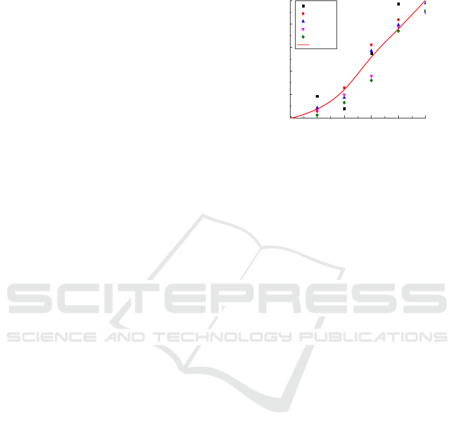
Figure 3 is a scatter plot showing the relation
between freeze-thaw and mass Loss of concrete with
different fiber contents, in which the curve data
fitted software ANSYS is used as a reference.
Conclusions can be drawn from Table 2 and Figure
3 as follows:
From the fitted curve and mass loss ratio line, it
can be seen that the change mass loss rate of
ordinary test block has no obvious rule, and the mass
loss rate even decreases when freeze-thaw cycles
reach near 80. The reason may be that the surface of
test blocks surface sheds and cracks after frozen
resulting in the water content in model aggregate
rises, and thereby the mass of concrete increases
after frozen.
The mass loss rate of 5% fiber concrete exceeds
5% after the freeze-thaw cycles exceed 160,
however, both cost and concrete agitation have a
certain influence when the fiber content is too high.
Therefore, it is considered that 10% fiber concrete is
most cost-effective and engineering practical.
0 40 80 120 160 200
0
1
2
3
4
5
0%
5%
10%
15%
20%
fitted curve
quality loss rate/%
freeze-thaw cycles/n
Figure 3:relation between freeze-thaw cycle count and
mass loss rate of concrete with different fiber contents.
5 CONCLUSIONS
Water has a great influence on the frost resistance of
concrete under freezing conditions. Thus, reducing
the water-cement ratio as much as possible without
increasing the strength and other properties of the
concrete in general is an effective measure to
enhance its frost resistance.
Under the freeze-thaw environment, the residual
compressive strength percentage of concrete and the
relative dynamic elastic modulus are basically
positively correlated, so it is appropriate to use the
relative dynamic elastic modulus as an indicator for
the durability performance of concrete in low
temperature freeze-thaw environment;
Proper amount of fiber content can enhance the
durability of concrete. Combining with the
economical and practical nature of concrete, it is
concluded that concrete with approximately 10%
fiber content is the most suitable.
REFERENCES
1. XU T C, ZHAO B D. The experimental study on
mechanical properties and durability of the basalt
Fiber Self-compacting Concrete [D]. Shenyang:
Shenyang University,2017.
2. MU R.A brief analysis of concrete freeze-thaw cycle
test and theoretical research[J]. Concrete,2016,37(6):
145-148.
3. LIU W D.Research on damage of fibre concrete under
action of ferrze-thaw cycle[J].Journal of Building
Structures, 2008,29(1):124-128.

4. ZHOU Z Y.Deformations of concerete under difgerent
freeze-thaw test conditions[J].Concrete, 2010,214:20-
27.
5. WEI Q. Experimental analysis on properties of
concrete after freeze-thaw cycles under extra-low
temperatures[J].EngineeringMechanics,2013,30(Suppl
ement):125-131.
6. CHEN S J. Influence of freeze-thaw cycles on the
durability of reinforced concrete structure[D].
Shanghai: Shanghai Jiao Tong University, 2013.
7. National standards of the People's Republic of China.
Standard for test methods of long-term performance
and durability of ordinary concrete(GB/T-50082-
2009)[S].Beijing: China Construction Industry
Press,2009.
8. National standards of the People's Republic
ofChina.Design specification for durability of
concretestructures.(GB/T504-76-2008)[S].Beijing:
China Construction Industry Press,2008.
