
Study on Pressure Drop Characteristics of Oil-water Two-
phase Annular Flow in Horizontal and Inclined Pipes
Y Ling
1,*
, H B Zhang
1
, Y X Pan
2
, Q Wang
1
and Z P Shang
1
1
Department of Earth Science and Engineering, Hohai University, Jiangsu, Nanjing
210098, China
2
Department of Civil Engineering, Shaoxing Uiversit, Zhejiang, Shaoxing, 31200,
China
Corresponding author and e-mail: Y Ling, 1170747017@qq.com
Abstract. Annular flow pattern is an important flow pattern in oil-water two-phase flow,
especially plays an important role in drag reduction of heavy oil. But there are few researches
on the flow characteristics of two-phase annular flow with low viscosity. In order to study the
characteristics, the paper studied the slip ratio and pressure drop under different inclination
angles. In the study, the flow pattern and pressure drop are measured and recorded by high
speed camera, differential pressure gauge and automatic fast closing valve. The experimental
results compare with the results predicted by the two-fluid model, the homogeneous flow
model and VOF model. The results show that the friction pressure increases with the apparent
velocity and decreases with pipe inclination. Compared with the experimental data, the
accuracy of the two-fluid model is low, the VOF model is the most accurate, but the
calculation is large.The four homogeneous flow models are higher. Because the coefficient of
friction is given by the Reynolds number, so the accuracy of the predicted annular pressure
drop is high.
1. Introduction
The mixed flow of oil and water is a phenomenon often encountered in the oil industry. The study of
its flow law has important scientific value and wide engineering application value. However, due to
the complexity of the oil-water two-phase flow, it is necessary to design a reasonable model program
to conduct an in-depth study on its characteristics. Two-phase or multiphas flow is different from the
single-phase. Multiphase flow contains immiscible phases, each with a set of flow variables, so the
flow parameters increase several times. In the flow process,due to the distribution of each phase
changes, there is a velocity slip between each phase and the interaction between phases will have an
impact on the overall flow. Different flow patterns are affected by factors such as inlet velocity and
pipe inclination. Different flow patterns have different flow law. In general, the flow law under a
certain flow pattern can not be applid to other flow patterns. [1-3]
For the division of two-phase flow pattern, there can be divided into stratified flow, dispersed
flow, slug flow, block flow, interrupted flow and annular flow due to the the different flow
conditions or pipeline parameters. For oil-water two-phase flow, the annular flow is very important
for pipeline transportation and oil exploitation because of its special section phase distribution. Its
170
Ling, Y., Zhang, H., Pan, Y., Wang, Q. and Shang, Z.
Study on Pressure Drop Characteristics of Oil-water Two-phase Annular Flow in Horizontal and Inclined Pipes.
In Proceedings of the International Workshop on Environmental Management, Science and Engineering (IWEMSE 2018), pages 170-177
ISBN: 978-989-758-344-5
Copyright © 2018 by SCITEPRESS – Science and Technology Publications, Lda. All rights reserved
water phase forms an annular contact with the wall, while the oil phase is distributed at the core of
the pipe and does not contact the wall. Because heavy oil can effectively reduce friction pressure
drop, increase production efficiency and reduce equipment loss, the research literatures about heavy
oil are much more. However, there are a few literatures about the study of the flow characteristics of
two-phase toroidal flow with light oil, the frictional pressure drop and the slope of phase cross-
section in horizontal and inclined pipes. The two fluid model, four homogeneous flow model and
VOF model can predict the friction pressure drop of the oil and water two phase flow according to
the related parameters.[4-14] Based on the data measured in the experiment, this paper studies the
pressure drop characteristics of annular flow by the obtain experimental data of slip ratio and
pressure drop, compared with the predicted results of different numerical simulations.
2. Experimental system and data acquisition
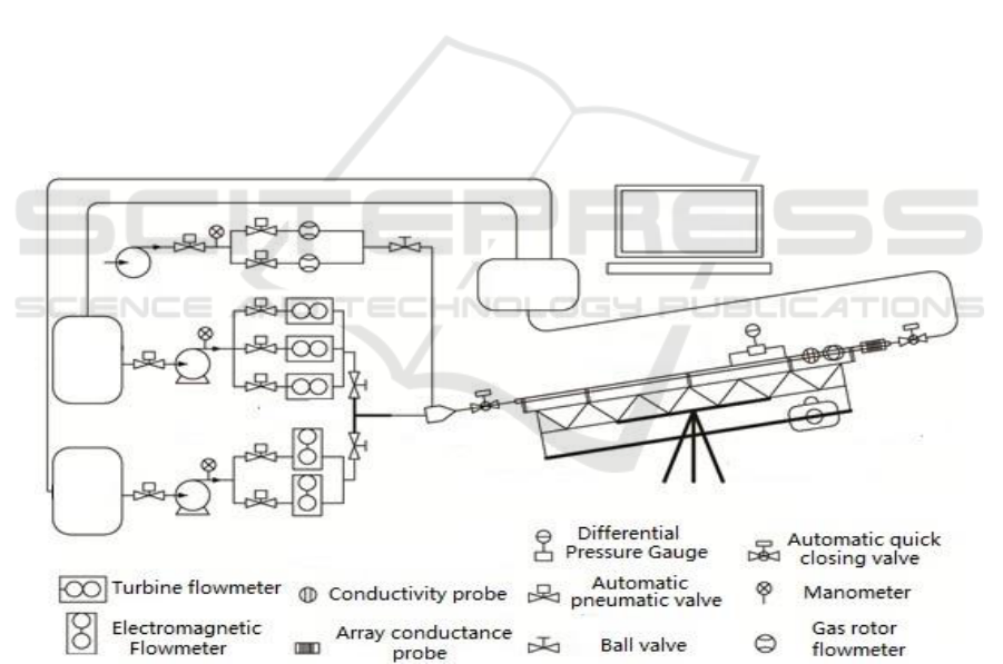
The experiment is carried out in the multi-phase flow laboratory of Daqing Oilfield. Figure 1 shows
the experiment device, it mainly includes circulation system, control system and measurement system.
The circulation system includes the supply equipment, the test section, the separation device The
circulation system includes the supply equipment, the test pipe section and the separating unit. The
supply equipment including the oil and water supply, and both the storage tank and the storage water
tank volume are 1 m
3
. The oil phase flow realize high precision control through three pipelines and
ajusted pump speed by frequency converter, and water phase flow realize it through two pipelines
and ajusted pump speed by frequency converter. The oil and water phase flow-rate is measured in
real time by the turbine flowmeter and the electromagnetic flowmeter respectively. The maximum
flow rate of oil phase and water phase is 60 m3 / d and its control error is ± 1%.
Figure 1. Schematic of the multiphase-flow test facility.
3. Test results and analysis
3.1. Annular flow pattern
In the experiment, the distribution of the phase in the pipeline is recorded by high-speed camera, and
the flow pattern under different dip angles was given in Figure 2. It can be seen from the figure, the
annular flow as oil phase is surrounded by water, oil phase are all concentrated in the center of the
Study on Pressure Drop Characteristics of Oil-water Two-phase Annular Flow in Horizontal and Inclined Pipes
171
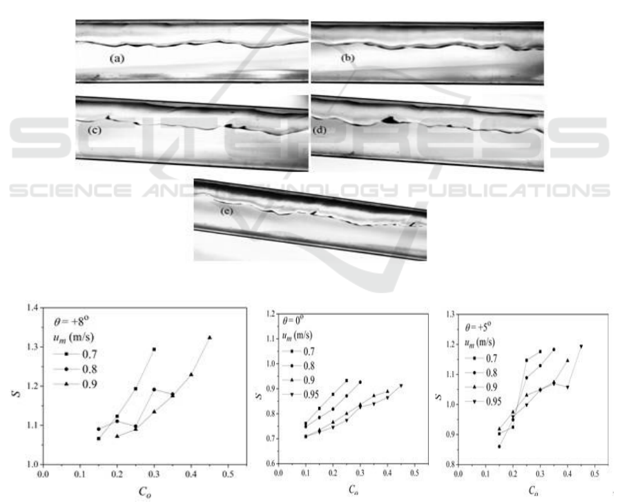
pipe, no contact with the wall, and water along the well wall to form an annular liquid, two-phase
were maintained, divided into positive and eccentric annular flow. The annular flow in the horizontal
wells mainly occurs in the range of 80%-95% water content, while the inclined wells are mainly in
the water content of 80%-90% within the ring flow. In the horizontal and inclined annular flow, the
interface between oil and water is smoother, while the lower interface is wavy interface.
3.2. The slip ratio of annular flow
Water pipe than the true flow velocity of the two phases is called the slip ratio and the slip ratio is
present at the interface source of friction stress. Figure 3 shows the relationship between the different
slip ratio (S) and the inlet oil content (C
0)
. The slip ratio has an increasing relationship with the inlet
oil content in the given dip angle. The increasing rate is related to the inlet velocity and the
inclination angle. It decreases with the increase of inlet velocity and increases with the increase of
well inclination angle. This shows that the inclination of the well has a great influence on the flow
velocity difference. Because the direction of the force by the oil phase volume and flow direction
angle is from 0°-90° degrees in the updip direction of oil wells. When the well inclination increases,
the volume force component in the direction of flow increases, resulting in accelerated flow of oil
phase.
Figure 2. Annular flow pattern u
m
= 0.74 m/s, C
w
= 0.80, = (a) 0
o
(b) +1
o
(c) +3
o
(d) +5
o
(e) +8
o
.
Figure 3. The relation between slip ratio and oil cut for AN flow.
IWEMSE 2018 - International Workshop on Environmental Management, Science and Engineering
172
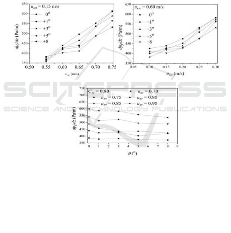
3.3. Friction pressure drop
In the study of pipeline flow, pressure drop is an important parameter to solve the problem of oil
industry, and it is significant to improve the efficiency of industrial production. The frictional
pressure drop of oil-water two-phase is not only influence by the apparent velocity, but also the
pipeline inclinaton. The pressure drop changes under different pipe dip angles were tested in the
above experimental system. In Figure 4, it shows the variation of the friction pressure drop with the
apparent velocity of water and oil phase. The friction pressure drop of the five kinds of wells is a
nearly increasing. In Figure 5 , it shows the relationship between the frictional pressure drop and the
pipeline inclination when the inlet moisture content C
w
= 0.80 and the mixing flow rate increases
from 0.70 m / s to 0.90 m / s .
Figure 4. Frictional pressure drop as a function of superficial velocity.
Figure 5. Frictional pressure drop as a function of pipe inclination.
3.4. Numerical calculation of friction pressure drop
The homogeneous flow model, the two-fluid model and the VOF model can be used to calculate the
pressure drop of the two-phase flow.[7-11] Based on the obtained section rate, the pressure drop can
be predicted, including the total pressure drop and the friction pressure drop:
0
0
0
- sin
- sin
t i i
f
ii
w
dp S
g
dz A
dp
S
g
dz A
(1)
Study on Pressure Drop Characteristics of Oil-water Two-phase Annular Flow in Horizontal and Inclined Pipes
173

Where
is the total pressure drop,
is the friction pressure drop,
is the oil-water interface
length,
is the oil-water interface shear stress,
is the oil cross-sectional area,
is the oil
density,and
is the cross- inclination.
In addition to the two-fluid model, more scholars use homogeneous flow model to predict
pressure drop [8-10]. The homogeneous flow model assumes that there is no relative velocity in the
two phase flow. The action mechanism of resistance is the same. The mixing the phase is
homogeneous. The mixed viscosity is calculated according to the difference of continuous flow, and
the friction pressure drop is calculated by the Blasius equation
2
2
t m m m
dp f
dz D
(2)
Where D is the diameter of the pipe and m is the average density of the two phases. The value is
obtained by averaging each phase, ie:
; fm is the friction coefficient between the
fluid and the pipe . By Blasius hypothesis, its form can be fm = CRe-n, the value is as follows:
35
0.25
1
, 2100
0.079
- ,2.1 10 10
Re
m
m
m
m
m
R
R
f
R
(3)
Where Rem is the mixed Reynolds number for two-phase flow,
,and
different scholars give different calculation methods for mixed viscosity m. Jana
[8]
et al give the
calculation of formula (4):
0
11
mw
xx
(4)
Where x is the oil phase weight fraction. Flores et al suggest that the mixed viscosity in the oil-
water two-phase dispersion stream takes the viscosity of the continuous phase. In addition, Arney
[11]
gives the calculation method of friction coefficient of different fluid and tube wall in the
homogeneous model, as shown in the following equation (5):
0.25
0.136
Re
m
m
f
(5)
Where the Reynolds number Rem is calculated as follows:
4
0
Re 1 1
m m w
m
w
D
(6)
The mixed density is
, where
.
Bannwart predict the pressure drop of aqueous two-phase flow friction according to the single-
phase frictional pressure drop, the following equation:
0.1
,
0.286
n
f
ww
dp
pC
n
dz L
(7)
Where Δpw is the single-phase frictional pressure drop. The calculation method is as follows (8) :
IWEMSE 2018 - International Workshop on Environmental Management, Science and Engineering
174

2
2
w w m
w
fL
p
D
(8)
Where the friction coefficient
, which Reynolds number
.
VOF is a surface tracking method that is fixed under a fixed Euler grid. Oil-water two-phase fluid
is immiscible with each other, the frictional pressure drop can be solved according to the formula its
momentum equation:
( ) ( )
T
vv p v v g F
t
(9)
Where
()
T
vv
is viscous force. The constitutive equation plug into the momentum equation,
and then integrate.The equation of friction pressure drop can be obtained, that is, the N-S equation.
Table 1. Prediction accuracy of each model.
Two-fluid model
Flores
Jana
Arney
Bannwart
VOF
APE
0o
25.08
-10.12
-3.22
-8.26
-3.76
0.19
+1o
19.56
-7.14
0.18
-5.19
-0.15
-1.93
+3o
19.25
-4.84
2.13
-3.09
2.25
-1.83
+5o
18.39
-2.19
5.29
-0.25
5.45
-2.73
+8o
21.41
0.33
7.08
1.92
7.53
-3.28
AAPE
0o
25.08
10.12
4.87
8.26
4.94
1.99
+1o
19.56
7.15
3.65
5.43
3.53
2.07
+3o
19.25
5.27
4.21
4.20
4.33
2.08
+5o
18.39
3.31
6.23
3.53
6.40
2.73
+8o
21.41
3.55
7.99
4.66
8.37
3.28
SD
0o
26.04
10.63
6.21
9.15
6.30
2.23
+1o
21.73
8.01
5.09
6.54
5.01
2.29
+3o
20.68
6.21
5.27
5.09
5.44
2.27
+5o
22.80
4.56
8.21
4.62
8.41
3.32
+8o
24.20
4.24
9.41
5.15
9.83
3.55
Horizontal and inclined oil-water two-phase annular flow frictional pressure drop are predicted by
two-fluid model and homogeneous flow model which include the four models given by Flores, Jana,
Arney and Bannwart respectively, and the VOF model Flow field characteristics. Analysis for the
prediction accuracy of the model, the calculated predicted and experimental values comparison.In
Table 1, by comparing the corresponding errors, including the average percentage error (APE), the
average absolute percentage error (AAPE) and the standard error (SD) shows that the VOF model
results in the pressure drop closest to the experimental data, the two-fluid model predictive results
much larger than the experimental value, and the four homogeneous flow model is between the two.
Although the VOF model is ideal, it is not economical to calculate the voltage drop for large
calculation . In addition, the VOF model in the inclined well underestimates the pressure drop value.
As the well angle increases, the deviation of the pressure drop calculation result and the experimental
data becomes larger. The two-fluid model is higher than the actual pressure drop in all well angles,
Study on Pressure Drop Characteristics of Oil-water Two-phase Annular Flow in Horizontal and Inclined Pipes
175

because the two-fluid model is mainly used to calculate the stratified flow rate and pressure drop,
while ignoring the pipe wall is surrounded by water friction coefficient decreases ,such as a circular
flow or a two-phase flow in which the wall is prewashed by water.
4. Conclusions
In this paper, the flow characteristics of horizontal and inclined oil-water two-phase annular flow are
studied, and the shear rate, phase-slip ratio and pressure distribution are analyzed. The relationship
between the slip ratio and the oil content of the inlet was analyzed by using the two - fluid model and
the VOF model. The friction pressure drop is calculated by the two-fluid model, the four
homogeneous flow models and the VOF model. The main conclusions are as follows:
1) The slip ratio of annular flow is in increasing relation with the oil content in the inlet, and the
increasing rate is related to both the inlet velocity pipe and the dip, and decreases with the
increase of inlet velocity, and increases with the inclination of the well.
2) The total pressure drop of the annular flow increases with the apparent flow velocity,while
dcreases with pipe inclination. The friction pressure drop of the VOF model is obtained by
using the two-fluid model. Compared with the VOF model and the results of the four
homogeneous flow models, the deviation from the experimental data is the largest, and the
deviation of the friction pressure calculated by the VOF model is the smallest in the middle.
The homogeneous phase flow model is used to predict the pressure drop in a dispersed flow
but the prediction results are better in a toroidal flow where the pipe wall is in contact with
the water phase due to the very simple phase of contact with the pipe wall in the toroidal flow
which is related to Reynolds number and the friction coefficient is stable.
Fund project
National Science and Technology major project "large-scale oil and gas fields and coalbed methane
development" sub-topics (2016ZX05019001-011)
National Natural Science Foundation of China (41374116)
National Natural Science Foundation of China (416774113)
References
[1] Zhai L S, Jin N D, Zong Y B and et al 2015 Experimental flow pattern map, slippage and
time–frequency representation of oil–water two-phase flow in horizontal small
diameter pipes. Int. J. Multiphase Flow 76 p168-186.
[2] Jana A K, Das G and Das P K 2006 Flow regime identification of two-phase liquid–liquid
upflow through vertical pipe. 61 p1500-1515
[3] Lum J Y L, Al-Wahaibi T and Angeli P 2006, Upward and downward inclination oil–
water flows. Int. J. Multiphase Flow 32 p413-435
[4] Rodriguez O M H, Bannwart A C and de Carvalho C H M 2009 Pressure loss in core-
annular flow: Modeling, experimental investigation and full-scale experiments J.
Petrol. Sci. Eng. 65 67-75
[5] Jiang F, Wang Y J, Ou J J andet al 2014 Numerical Simulation of Oil-Water Core Annular
Flow in a U-Bend Based on the Eulerian Model. Chem. Eng. Technol p 659-666
[6] Kumara W, Halvorsen B and Melaaen M C 2009 Velocity and turbulence measurements
of oil-water flow in horizontal and slightly inclined pipes using PIV. Computational
Methods in Multiphase Flow V, p277.
[7] Kumara W A S, Halvorsen B M and Melaaen M C 2010 Particle image velocimetry for
characterizing the flow structure of oil–water flow in horizontal and slightly
inclined pipes. Chem. Eng. Sci. p4332-4349
IWEMSE 2018 - International Workshop on Environmental Management, Science and Engineering
176

[8] Jana A K, Ghoshal P, Das G and et al 2007 An Analysis of Pressure Drop and Holdup for
Liquid-Liquid Upflow through Vertical Pipes. Chem. Eng. Technol, p 920–925.
[9] Xu J Y, Li D H, Guo J and et al 2010 Investigations of phase inversion and frictional
pressure gradients in upward and downward oil–water flow in vertical pipes. Int. J.
Multiphase Flow p930-939
[10] Bannwart A C 1999 A simple model for pressure gradient in horizontal core. Journal of
Brazilian Society of Mechanical Sciences p223-244
[11] Arney M S, Bai R, Guevara E and et al 1993 Friction factor and holdup studies for
lubricated pipelining—I. Experiments and correlations Int. J. Multiphase Flow p1061-
1076
[12] Burlutskii E. 2017 CFD study of oil-in-water two-phase flow in horizontal and vertical
pipes. Journal of Petroleum Science and Engineering
[13] Pouraria H, Seo J K and Paik J K. 2016 Numerical modelling of two-phase oil– water
flow patterns in a subsea pipeline. Ocean Engineering 115 p135-148
[14] Shi J, Gourma M and Yeung H 2017 CFD simulation of horizontal oil-water flow with
matched density and medium viscosity ratio in different flow regimes. Journal of
Petroleum Science and Engineering, 151 p373-383
Study on Pressure Drop Characteristics of Oil-water Two-phase Annular Flow in Horizontal and Inclined Pipes
177
