
Three Dimensional Numerical Simulation of Oil Containment
Process by Flexible Oil Booms in Inland Waters
X Feng
*
, Y Y Zhang and Z W Wu
Marine Eng. College, Dalian Maritime Univ. Dalian 116026, China
Corresponding author and e-mail: X Feng, 530546168@163.com
Abstract. The deformation of oil containment boom in inland waters and the hydrodynamic
process are investigated based on multiphase CFD (Computational Fluid Mechanics) model
and the structure analysis model by system coupling. The velocity field near the flexible
boom under water current is compared with those behind the rigid boom. The process of
spilled oil interception by oil boom is simulated through employing the VOF (volume of
fluids) method to tracing the oil-water two phase flows and the variation of oil slick shape is
investigated.
1. Introduction
Inland water oil spills which are not so large scale compared with marine oil spills can still cause
serious damage to natural resources and to those whose livelihoods depend on these resources. With
regard to the bio-environmental impact, inland water oil spills could directly slay the organism such
as animals, plants and even the smallest micro-organisms by the toxicological reaction and hypoxia
effect [1].On the other hand, spilled oil could experience series of physical and chemical changes,
such as spreading, drifting, evaporation, emulsification, dissolution, and participate in the biological
cycle through the food chain and eventually endanger the human society. Therefore, it is important to
improve techniques and equipment that facilitate spill clean-up for inland water oil spills [2].
Effective use of skimmers or in situ burning for an oil spill generally requires that the spill first be
contained using booms which are frequently used in inland water conditions due to the simple water
conditions compared to sea water conditions. However, the booms often fail to hold the oil even in
simple inland water situations due to hydrodynamic forces, which will significantly boost the clean-
up costs. Therefore a better understanding of the oil containment process by oil booms is required. As
is pointed out by FENG [3], there are mainly six failure mechanisms for the oil boom as shown in
Figure 1: entrainment failure, drainage failure, critical accumulation failure, splash-over, boom
submergence and boom planning. The last three failure modes are usually caused by the wind and
wave effects which commonly happened in sea conditions and not so frequently for inland water
conditions. So only the first three failure modes are talked about here. The entrainment failure as
described by Leibovich [4] and Milgram et al. [5] is caused by breaking of Kelvin-Helmholtz water-
oil interfacial waves at sufficiently large relative velocity. The drainage failure usually takes place
when the boom draft is insufficient to contain the oil slick and some oil goes underneath the boom as
shown in Cross and Hoult[6]. As shown in many experimental results [7-8], a third failure
Feng, X., Zhang, Y. and Wu, Z.
Three Dimensional Numerical Simulation of Oil Containment Process by Flexible Oil Booms in Inland Waters.
In Proceedings of the International Workshop on Environmental Management, Science and Engineering (IWEMSE 2018), pages 463-468
ISBN: 978-989-758-344-5
Copyright © 2018 by SCITEPRESS – Science and Technology Publications, Lda. All rights reserved
463

mechanism-critical accumulation usually takes place in highly viscous oils of kinematic viscosities
exceeding 3000cSt, independently of the boom draft.
Figure 1. Six different modes of oil containment failure.
Although oil boom is widely studied, it is far from being fully investigated. For most of the
numerical study of the oil boom performance, the oil boom is usually considered to be rigid. As of
today, the PVC material is usually used as the skirt of the oil boom, which is flexible under the
current action. In this paper, the ANSYS14.5 software has been used to simulate the oil water flow
around a flexible boom used in inland waters. The details of the flow field before the flexible boom
skirt and the deformation process of the boom skirt are studied and the impact of boom deformation
on flow field is investigated in detail.
2. Governing equations
For the flows of incompressible fluid with the free surface, the governing equations are the continuity
equation and the Reynolds-averaged Navier-Stokes equations:
Continuity equation:
0
)()(
y
v
x
u
t
(1)
The incompressible RANS momentum equation solved in the software can be written as:
x
p
y
u
x
u
yx
u
xy
u
v
x
u
u
t
u
tt
2
)()()(
(2)
IWEMSE 2018 - International Workshop on Environmental Management, Science and Engineering
464

g
y
p
y
v
yy
u
x
v
xy
v
v
x
v
u
t
v
tt
2
)()()(
(3)
In which
t
is time and
is the density,
yx
,
denotes the Cartesian coordinates,
vu
,
is an
ensemble mean velocity component,
p
is the fluid pressure,
is the dynamic viscosity, and
g
is the
gravitational acceleration. The standard
k
model is adopted to compute the Reynolds stress and
the free surface is computed by the VOF method.
For computing the deformation of oil boom skirt, the conserving equations can be derived from
the Newton Second Law as shown in following:
(4)
In which
is the density of the oil boom skirt,
is Cauchy stress tensor,
is Volume force
vector,
is the acceleration vector. The deformation of the structure caused by the fluid can be
calculated by:
(5)
In which
is the mass matrix,
is damping matrix,
is the element stiffness matrix; is the
deformation and
is the stress.
For coupling the fluid equations and the structure equations, the following rules should be
satisfied:
(6)
(7)
3. Numerical simulations and analysis of the numerical results
3.1. Numerical model set-up
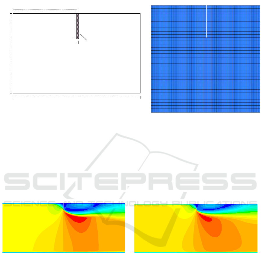
The computational domain is 20.04 m long, 5 m deep and 0.4m wide (see Figure 2). The oil boom is
placed near the surface and in the middle of the computational domain in length direction. The boom
draft D is chosen as 0.6 m. The current velocity U range is chosen of 0.2 - 0.7 m/s at interval of 0.1
m/s. The computational zones are discrete by the structured grids using MESHING, and the mesh
length is 0.04m, and the mesh height is 0.04m.
Three Dimensional Numerical Simulation of Oil Containment Process by Flexible Oil Booms in Inland Waters
465
20.04m
0.04m
0.6m
5m
10m
Oil boom
Figure 2. The schematic drawing and mesh of the computational domain.
3.2. The impact of the boom deformation on the flow field
As is known, the boom deformation has huge impact on the flow field near the oil boom which will
accordingly influence the performance of the oil boom. Here, the current velocity is chosen as 0.5m/s
and both rigid and flexible boom are considered. As shown in Figure 3, the effective boom draft of
the flexible boom is less than that of rigid boom with the same size due to the boom deformation. The
streaming location under the boom bottom for the flexible boom is risen up due to the boom
deformation, which making the streaming before boom easier. As compared with the rigid boom,
the whirlpool after the flexible boom is flat and long.
Figure 3. The contour plots of fluid velocity.
3.3. Numerical simulation of the oil containment process
Then, the oil containment process of the flexible boom is simulated. Here, the oil with
density=860kg/m
3
and viscosity =0.06kg/m-s is chosen as the experimental material, and the
initial oil volume Q is chosen as 1.516m
3
. The oil boom with modulus of elasticity E=1.2e
6
Pa and
Poisson ratio =0.49 is used. As shown in the initial contour map of the oil volume fraction(Figure
4), the red region indicate that the oil fraction equals 1 and the blue region indicate that the oil
fraction equals 0, and there is no boom deformation at initial moment.
IWEMSE 2018 - International Workshop on Environmental Management, Science and Engineering
466
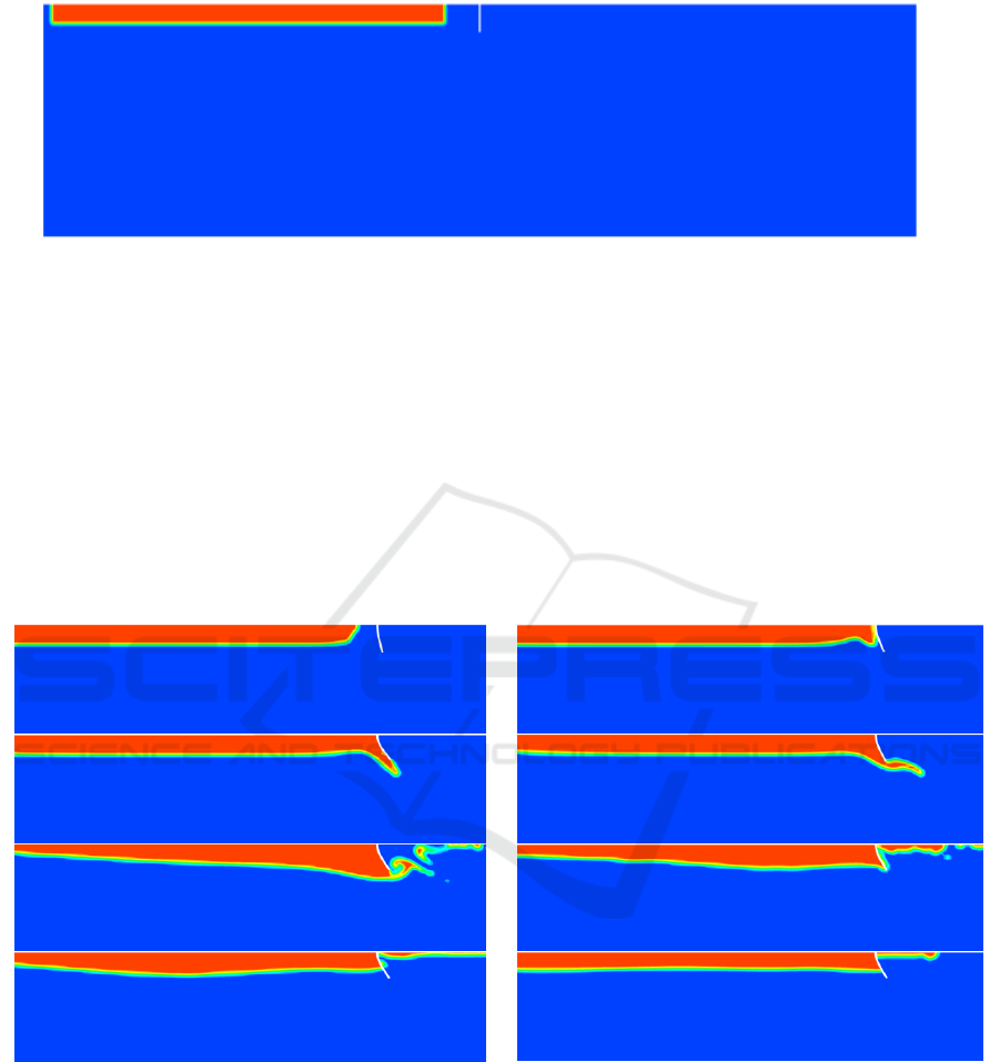
Figure 4. The contour plot of oil volume fraction at initial moment.
Figure 5 shows the variations of oil shape and the oil containment and the boom deformation
process. As is shown, the oil floating on the water will expand and move towards the oil boom under
the current, and the flexible boom skirt will deform. As the oil slick approaching the boom, it will
accumulate before the boom with the length of the oil slick decreased and the thickness increased. At
time t=2.4s, the oil slick will escape under the bottom of the boom and then the drainage failure
happens. After escaping from the bottom of the boom, part of the oil slick will flow with the current
and part of the oil will be retained after the boom under the action of buoyancy. The total simulation
time is 120 seconds and after that the oil slick shape will maintain unchanged shown in the last
picture in Figure 5.
Figure 5. Variations of oil shape outlined by the oil volume fraction contour plot.
at t=0.8s, 1.6s ,2.4s, 3.2s, 6.4s, 12.8s, 21.6s and 120s
4. Conclusions
Based on the analysis of Fluid-Structure Interaction, the deformation of oil boom under pure current
condition is numerically simulated. Then, the simulations of flow passing a rigid boom and a flexible
boom are carried out, which provides the possibility to compare velocity fields for different booms.
When the body of boom deformed, the fluid field in the vicinity of the boom changed, and oil
containment is affected. The process of spilled oil interception by oil boom is simulated through
Three Dimensional Numerical Simulation of Oil Containment Process by Flexible Oil Booms in Inland Waters
467

employing the VOF (volume of fluids) method to tracing the oil-water two phase flows and the
variation of oil slick shape is investigated. Compared with the rigid boom, the whirlpool after the
flexible boom is flat and long. During the oil containment process, the oil floating on the water will
expand and move towards the oil boom under the current, and the flexible boom skirt will deform.
Acknowledgement
This research is supported by the National Natural Science Foundation of China (Grant No.
51409032, the Fundamental Research Funds for the Central Universities (Project No. 3132017006,
China).
References
[1] Teal J M and Howarth R W 1984 Oil spill studies: A review of ecological effects
Environmental Management 8(1): 27-43.
[2] Gong K, Tkalich P and Xu H H 2014 The numerical investigation on oil slick behavior behind
the oil boom Journal of Environmental Protection 5: 739-744
[3] X Feng and W Q Wu 2011 Numerical experimental set-up of oil containment by boom and
investigation on containment failure PH.D thesis Dalian Maritime University, Dalian
[4] S Leibovich 1976 Oil Slick Instability and the Entrainment Failure of Oil Containment Booms
Journal of Fluids Engineering 98 98-103.
[5] Milgram J H and Van Houten R J 1978 Mechanics of a Restrained Layer of Floating Oil
above a Water Current Journal of Hydronautics 12 93-108.
[6] Cross R H and Hoult D P 1971 Collection of Oil Slicks. Journal of the Waterways, Harbors,
and Coastal Engineering Division Proceedings of the American Society of Civil Engineers
97 313-322
[7] Lee C M and Kang K H 1997 Prediction of Oil Boom Performance in Currents and Waves
Spill Science & Technology Bulletin 4 257-266.
[8] Violeau D, Buvat C, Abed-Meraim K and De Nanteuil E 2007 Numerical Modeling of Boom
and Oil Spill with SPH Coastal Engineering 54 895-913.
IWEMSE 2018 - International Workshop on Environmental Management, Science and Engineering
468
