
A New Method of InSAR Phase Unwrapping Processing
Considering the Terrain Factors
J G Liu
1
, J F Wang
1
, Z L Wang
1
and W K Liu
2,*
1
Power Supply Ltd of Tai an, Shandong, 8 Dongyue street, Taishan district, Taian
city, Shandong province China
2
Center of information, Shandong University of Science and Technology, 579
Qianwangang Road, Qingdao, China
Corresponding author and e-mail: W K Liu, weike.liu@163.com
Abstract. Interferometric synthetic aperture radar interferometry (InSAR) phase unwrapping
is influenced by the terrain factors, how to consider the terrain factors especially the complex
ones is meaningful to the unwrapping algorithm. In order to solve this problem, based on the
terrain phase statistical information, this paper proposes a phase gradient estimation(PGE)
model applied for the additional constraint condition to the nonlinear least squares phase
unwrapping. It involves the model not only eliminates noise influence, but also considers the
terrain factors. Finally, real data unwrapping experimental results, comparing the proposed
algorithm with classical approaches, illustrates the effectiveness the PGE phase unwrapping
algorithm could be used to eliminate the effect of topography variation in the unwrapping
process.
1. Introduction
Interferometric synthetic aperture radar (InSAR) phase unwrapping is one of the most important
steps to obtain the DEM and minor deformation of topography[1], but it is also influenced by the
topography factors, which is the main source of errors for InSAR products.
Currently typical phase unwrapping methods are based on the optimal estimate, such as weighted
method [2], instantaneous frequency (IF) estimation method [3], nonlinear Kalman filter method [4],
nonlinear phase model algorithm [5] and ant colony optimization algorithm [6] and so on. Typical
algorithms are based on the assumptions: the topography is continuously changing, but the main
interferometric phase values are discontinuous, the growth of ground range sampling rate and
baseline de-coherence lead to the actual phase unwrapping errors. Therefore, taking into account the
topography factors to the phase unwrapping, it could be effective to introduce the topography-related
input control variables in phase unwrapping models. There are three ways to take into account the
terrain factors: 1) using the interferometric phase spectrum shift, which is closely related to the angle
of terrain slope [7]; 2) using the linear phase of the interferometric phase to estimate the slope of the
topography [8]; 3) using the obtained DEM of the region from optical or US space mission SRTM.
In this paper, based on the topography statistical information, the phase gradient estimation (PGE)
model is proposed as the constraint condition of the nonlinear least squares phase unwrapping
algorithm. Finally, the unwrapping experimental results show that this algorithm is accurate and
672
Liu, J., Wang, J., Wang, Z. and Liu, W.
A New Method of Insar Phase Unwrapping Processing Considering the Terrain Factors.
In Proceedings of the International Workshop on Environmental Management, Science and Engineering (IWEMSE 2018), pages 672-680
ISBN: 978-989-758-344-5
Copyright © 2018 by SCITEPRESS – Science and Technology Publications, Lda. All rights reserved

robust. The algorithm could effectively take into account the topography factors and restrains the
errors propagation.
2. PGE model
Suppose the slope angle is
τ
in the SAR interferogram. In the vertical (perpendicular to the orbit) and
azimuth (parallel to the orbit) direction, the average angles are
y
τ
and
x
τ
. The slant distance of the
two points is the (1):
22 22
10 0 0 0
()()()
vh
R
RR Hz B yB Hz yΔ= − = − + + − − − +
(1)
Then the phase difference
RΔ can convert into the components sum of three directions: in line of
sight (LOS), azimuth and vertical direction. The (2) shows the phase difference caused by the
topography deformation which could respectively decompose in three vector directions:
() ()()
()
()()( )
01 11 10
11 0
10
0
0
0
44
4
cos sin
1tantan
()
2tan
tan cos
4
()
sin( )
cos
sin( )
y
xy
y
y
y
RR RR RR
RB zz R
RR
B
xx
R
B
h
R
ππ
φ
λλ
π
θα θ
λ
θτ
θ
ττ
π
λθτ
τ
θτ
⊥
⊥
′′
Δ=− ⋅ − = ⋅ − + −
=⋅Δ+ − −⎡⎤
⎣⎦
⎡⎤
+
⎛⎞
′
−+
⎢⎥
⎜⎟
⎢⎥
⎝⎠
⎢⎥
⎢⎥
=−+
⎢⎥
−
⎢⎥
⎢⎥
⎢⎥
−
⎢⎥
⎣⎦
(2)
Where
θ
is the incidence angle, and
()
12 1 2
2
θθθ θθ
=+ ≈≈ ,
012 0
BR
θθθ
⊥
=−≈ ,
0
cos ( )
y
yy S
τ
′
=−
,
000
R
RR
′
Δ= −
,
111
R
RR
′
Δ= −
,
00 0
( ) ( ) tan sin ( ) tan
yx x
zz yy h xx h
ττ τ
−=− +=− +
,
10
sin ( ) sin( ) cos
yy
Ryy
θθττ
=Δ − = −
,
1
sin( )
y
SR
θτ
′
=Δ −
.
Let the vector
11
[]
22
TT
T
rx
fff
Rx R x
φφ φ φ
ππ
∂∂ ΔΔ
⎡
⎤⎡ ⎤
Δ=Δ⋅Δ = ⋅ = ⋅
⎢
⎥⎢ ⎥
∂∂ ΔΔ
⎣
⎦⎣ ⎦
represents the LOS and azimuth
2D IF. In order to obtain relationships of the IF component and the slope angle in the two directions,
we project and divide the three vectors of the (2) in the three directions along the LOS and azimuth
direction:
()()
1tantan
1
2 tan 2 tan tan
tan cos
tan
sin( ) sin cos tan
y
r
yy
xy
x
xB B
yy
f
R
fk k
x
θτ
φ
θτ θ τ
ττ
τ
φ
θτ θ θ τ
+
⎧
∂
Δ= = =
⎪
∂
−−
⎪
⎨
∂
⎪
Δ= = =
⎪
∂− −
⎩
(3)
Where
0
4
B
B
k
R
π
λ
⊥
= . The (3) has the same results as in reference [3]. Suppose the slope gradient
vector is
[tan tan ] [ ]
TT
yx yx
ddd
ττ
==
, which is also the IF’s function in azimuth and range direction
(4):
A New Method of Insar Phase Unwrapping Processing Considering the Terrain Factors
673

()()
(,)
()2 tan 12 tan
xx x
yr r r
dfW fW
df f f
θθ
Δ=Δ
⎧
⎪
⎨
Δ=Δ − Δ+
⎪
⎩
(4)
Where
cos (tan )
y
B
Wdk
θθ
=−
.When the angle of topography range slope tends to
θ
, the number
of fringe wave is increasing. It was shown in the reference [7] that the probability density function
(PDF) of topography slope gradient was log-normal distributed in different topography conditions. In
the discrete InSAR interference image, hypothesis the slope gradient azimuth and range component
are independent and distributed identically. The 2D slope gradient PDF formula is (5):
()
()
() log cos
() log cos
x
y
dx d x
K
dy d y
K
Fd L d
Fd L d
πτ
πτ
⎧
=
⎪
⎨
=
⎪
⎩
∑
∑
(5)
Where
K
is the size of phase estimation window,
log
x
d
L
and
log
y
d
L
are Log-Levy distribution of
the gradient components. According to the (5) and the relationship between the IF (3) and topography
slope (4), we get the IF-PDF function (6):
()
()( )
() ()
() ()
cos sin
cos arctan sin arctan
rrdy
xxdx
yy
yy
func f k f F d
func f k f F d
dd
ρ
ρ
ρτθτ
θ
Δ=⋅Δ
⎧
⎪
Δ=⋅Δ
⎪
⎪
⎨
=−
⎪
⎪
=−
⎪
⎩
(6)
Where
k
is the proportionality constant,
ρ
is the phase sampling rate in azimuth and
range direction. According to the above transformation between the phase gradient and IF which is
described in (3), the range PGE model function is (7):
11
()
22
y
y
y
Pfunc
y
y
φ
φ
φ
ππ
Δ
Δ
⎛⎞
Δ= ⋅
⎜⎟
ΔΔ
⎝⎠
(7)
The azimuth PGE model function is (8):
11
()
22
x
x
x
P func
x
x
φ
φ
φ
ππ
Δ
Δ
⎛⎞
Δ= ⋅
⎜⎟
ΔΔ
⎝⎠
(8)
The (7) and (8) show that the PG can be obtained by the IF-PDF model. The changing trend and
the residual of the phase gradient could be deduced from the PG estimation (PGE) function.
3. PGE Experiments
The primary parameters of the simulation experiments are shown in the Table 1.
Table 1. Seleted parameters of image experiment data.
Baseline
Distance(m)
Image
Range(m
2
)
Ratio (m) Satellite
incidence(
o
)
satellite
altitude (km)
radar
wavelength (m)
200 41
×
41 27 19 785 0.057
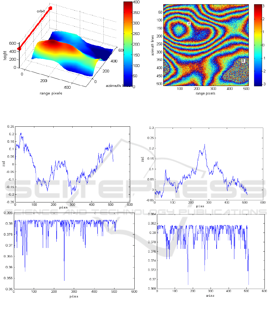
In the simulation interferogram (see Figure1) is obviously divided into two parts, the blue one is
the body of water, the rest is mountain and the highest part is 300 meters
high.Assuming
0SNR db=
the simulation uses the PG estimation function
IWEMSE 2018 - International Workshop on Environmental Management, Science and Engineering
674
a b
Figure 1. interferogram simulation(a) 3D interferogram, (b) Wrapped phase interferogram.
Parts A and B are the two obvious representative regions (see Figure 1(b)). A represents the
mountains, B represents the water regions where there is the pure noise in the interferogram.
a b
c d
Figure 2. The comparison of IF estimation with PGE model of the 150 line.
(a)IF estimation in the azimuth direction; (b) IF estimation in the range direction;(c) PGE model in the
azimuth direction; (d) PGE model in the range direction.
A New Method of Insar Phase Unwrapping Processing Considering the Terrain Factors
675
a b
c d
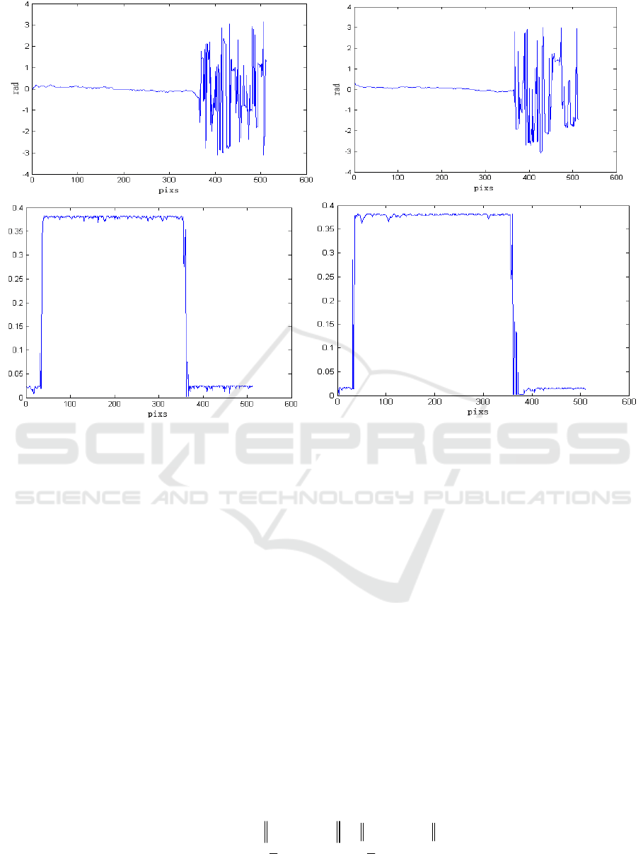
Figure 3. The comparison of IF estimation with PGE model of the 450 line.
(a)IF estimation in the azimuth direction; (b) IF estimation in the range direction;(c) PGE model in the
azimuth direction; (d) PGE model in the range direction.
Figure 2 and Figure 3 make comparisons of the IF estimation and PGE model after the
transformation of the 150 row and the 450 row of the cross section. It can be seen from Figure2
(a) and Figure2 (b), even in similar topography parts of the interferogram, the frequency still change
greatly relative to the PGE model in Figure 2(c) and Figure 2(d).
In Figure 3 (a) and Figure 3 (b), the shadow region caused by the water regions, the IF estimation
cannot reflected the changes, but for Figure 3 (c) and Figure 3 (d), the PGE model in the shadow
areas, values are close to 0, so it reflects more accurately, that also means the it is more stable than
the frequency in steep topography and shadow regions. Not same with the azimuth, the PGE in the
range direction depends on the slope along the track direction and perpendicular to the track
direction, which is the same as formula (4). By calculating the known region of interference, the
superiority of PGE parameter model could able to estimate and infer the phase gradient in distortion
regions, which could get the more accurate estimates.
4. Phase unwrapping model and Unwrapping experiments
The topography slope derivation formula (3) shows that the trend of topography variation is
nonlinear [9]. Using the additional constraints of the PGE model to pre-estimate phase gradient, the
least squares phase unwrapping algorithm is taking into account the nonlinear variation of the
topography slope. The nonlinear least squares phase unwrapping with PGE constrain is as (9):
2
2
1
|, |,
min ( ) 2 2
.. [ ( | , ) ( | , )]
yy xx
tt
xy xy
Lff
st P x y P x y
ψψ
φφπ φπ
ψψξ
−
ΔΔ
=Δ − +Δ −
−<
(9)
IWEMSE 2018 - International Workshop on Environmental Management, Science and Engineering
676
This unwrapping model represents the minimizing deviation of all unwrapped phase frequency
with the wrapped one. And the constraint ensures that the twice iteration difference of the phase
gradient values is tending to zero. The model function (9) is the non-linear constraint formula due to
the constraint is non-linear.
Generally, there are two ways to solve nonlinear equations, one is to use the prior knowledge to
determine the initial value to reduce the amount of calculation, and then use the quadratic
programming methods or techniques based on the global trust-region strategy. In addition, the
constrained optimization problem can be transformed into the non-constrained optimization problem
[10]. In order to test and verify the effectiveness of the PGE unwrapping algorithm, the experiment
uses two CEOS scenes of the ALOS satellites in the Middle East from July 24, 2007 and September
8, 2007. Interferometric regions have large terrain undulation and rich details.
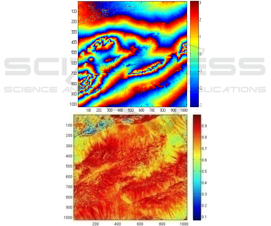
The Figure 4 shows the original cutting interferogram corresponding image block size is 1024 *
1024 pixels. The experiment compares the algorithms of LS, WLS and Snaphu[11] (classic minimal
network flow unwrapping algorithms) with PGE phase unwrapping algorithm. The unit is pixel in
Figure 4.
a b
Figure 4. Original and coherence of the Middle East ALOS satellite interferogram.
(a)original interferogram, (b) coherent.
A New Method of Insar Phase Unwrapping Processing Considering the Terrain Factors
677
The result of original phase interferogram of 4(a) and coherent of 4(b) shows that the highlight of
the regional coherence is well, dark spots regional coherence is poor. The relationship between the
topography experimental regions with its expanded the phase is
(, ) (, )4Hxy xy
λ
φ
π
=
, that formula
can be used inverting landscape and get the three-dimensional surface topography [12], as is shown
in Figure 5.
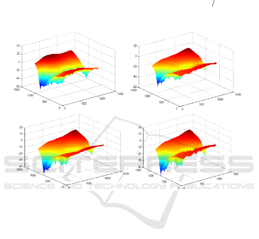
a b
c d
Figure 5. 3D phase unwrapping images (a)LS Phase unwrapping, (b) WLS Phase unwrapping,
(c) Snaphu Phase unwrapping, (d) PGE Phase unwrapping.
The unwrapped 3D Figure 5(a~d) reflect that LS phase unwrapping result is the smoothest result
even under the different topography conditions, but it also caused the global transmission of errors,
the unwrapped phase values range from -60 to 40. Relative to the LS algorithm, WLS and Snaphu
phase unwrapping methods are better reflect the quality of the different topography areas, but it could
not distinguish different kinds of phase information, the unwrapped phase values range from -60 to
20 and -40 to 20. For the two algorithms does not consider the influence of topography factors, the
regional unwrapped results is deviated from the actual existence of the topography changes,
especially in the regions where topography changes abruptly. The PGE algorithm reflects the more
detailed than the optimization algorithms, which proves the method can reduce the effect of phase
residuals caused by the topography factors. The unwrapped phase values range between -40 to 20, it
takes into account the topography factors of geometric distortion effects on unwrapping. Compared
with the other algorithms, it has a higher accuracy.
Table 2 compares a set of quantitative indicators to analyse the comparative merits of different
unwrapping algorithms.
IWEMSE 2018 - International Workshop on Environmental Management, Science and Engineering
678

Table 2. Unwrapped time, RMSE and
ε
values.
Algorithm Run Time(s) RMSE (rad)
ε
value(rad)
LS 93.69 10.7148 0.7763
WLS 198.98 3. 9802 0.5628
Snaphu 977.32 3. 3841 0.5269
PGE 638.73 2.0867 0.3269
The results are running in Matlab2008 environment Ubantu operating system
(Computer CPU is Intel (R) Pentium (R) 3.20GHz, memory is 2G).
It can be seen that the LS unwrapping algorithm has the least computation time. But compared
with the other quotas, Snaphu algorithm has the most running time. The reason is that finding the
minimum network flow takes more time on the large interferogram and but the number of phase
residuals is the largest. The running time of PGE unwrapping method is less than Snaphu but longer
than LS. It takes 192.630s to solve the frequency conversion, which was also added to the phase
unwrapping time. But the PGE has the best results in the rest of quotas: RMSE and the
ε
value. It
also shows that PGE algorithm is stability and adaptability that can get relatively reliable unwrapping
results. And the results provide a perfect fit to the phase gradient estimated based approach, which is
the probability of a biased estimate (shaded part) because of the topography to reduce the number of
generated residual handicap.
From all quotas, PGE unwrapping algorithm has more accuracy and adaptability to the method
regardless of topography factors. Based on the PG estimation model can estimate, optimize phase
gradient and guide LS optimization phase unwrapping. In the case of increasing the amount of
limited computing to take into account the topography factors, the approach has increased the ability
to resist the phase distortion.
5. Conclusions
The same InSAR interferogram has the same baseline, but different topography caused different slant
range, and then caused the different PG. In other words, different PG means different topography
information in the interferogram. In the local region, estimated PG reflects the changing trend of the
phase and the probability of the different PG falls in the corresponding interval. From the above
derived formulas, the phase IF is consistent with the variation of slope angle and the PG. Based on
the principle of Woodward [13, 14], by separately calculating the range and azimuth phase IF, the
statistical characteristics of PG could estimate the phase in different topography conditions, so the
PGE model can take into account the changes of topography factors and be applied into the phase
unwrapping as the constraint condition. The experiment shows unwrapped phases have more
accurate results than some typical phase unwrapping algorithms.
Acknowledgement
This work was supported by foundation of The National Natural Science Fund (40874001) and Key
Laboratory of Surveying and Mapping Technology on Island and Reef, State Bureau of Surveying
and Mapping (2010A01) ; Scientific research fund project for the introduction of talents of Shandong
university of science and technology (2014RCJJ047).
References
[1] Zhong H, Tian Z and Huang P 2015 A combined phase unwrapping algorithm for InSAR
interferogram in shared memory environment International Congress on Image & Signal
Processing pp 1504–1509
[2] Cui H H, Liao W H and Cheng X S 2010 Mathematic Descriptions and Analysis of Quality
A New Method of Insar Phase Unwrapping Processing Considering the Terrain Factors
679

Weighting Factors in Phase Unwrapping Algorithms ACTA OPRICA SINICA vol 30 (1) pp
97–104
[3] Liang M, Zhang Z B and Zhong J G 2016 Phase unwrapping guided by instantaneous
frequency for wavelet transform profilometry Journal of Optoelectronics laser vol 27 (8)
pp 853–862
[4] Xie X M and Zeng Q N 2015 Efficient and robust phase unwrapping algorithm based on
unscented Kalman filter, the strategy of quantizing paths-guided map and pixel
classification strategy Applied Optics vol 54 (31) pp 92–94
[5] Huang H F and Wang Q S 2014 A Method of Filtering and Unwrapping SAR Interferometric
Phase Based on Nonlinear Phase Model Progress in Electromagnetics Research vol 144 (1)
pp 67–78
[6] Wei Z Q, Xu F and Jin Y Q 2008 Phase unwrapping for SAR interferometry based on an ant
colony optimization algorithm International Journal of Remote Sensing vol 29 (3) pp 711–
725
[7] Guarnieri A M 2003 Using topography statistics to help phase unwrapping IEEE Proceedings
Radar Sonar Navigation vol 150 (3) pp 144–151
[8] Zhu D Y and Zhu Z D 2005 Improving the Coherence for InSAR Processing and Coherence
Estimation Using the Linear Phase Model ACTA ELECTRONICA SINICA vol 33 (9) pp
1594–1598
[9] Wang Z Y, Zhang J X and Huang G M 2014 Precise monitoring and analysis of the land
subsidence in Jining coal mining area based on InSAR technique Journal of China
University of Mining & Technology vol 43 (1) pp 169–174
[10] Liu W K, Liu G L and Tao Q X 2012 Nonlinear least squares phase unwrapping based on
homotopy method Science of Surveying and Mapping vol 37 (4) pp 126–128
[11] Syakrani N, Baskoro E T and Mengko T L 2015 New weighting alternatives to MCFN phase
unwrapping’, International Journal of Tomography & Simulation vol 28(3) pp 39–52
[12] Liu G L, Hao H D and Tao Q X 2009 The Implementation and Analysis of Kalman Filter
Phase Unwrapping Algorithm of InSAR International Conference on Geo-spatial Solutions
for Emergency Management (GSEM) and 50th Anniversary of Founding of Chinese
Academy of Surveying and Mapping XXXVIII pp30–34
[13] Boyd J P 2015 Convergence and error theorems for Hermite function pseudo-RBFs:
Interpolation on a finite interval by Gaussian-localized polynomials Applied Numerical
Mathematics vol 87 pp 125–144
[14] Chen C W and Zebker H A 2002 Phase unwrapping for large SAR interferograms: statistical
segmentation and generalized network models IEEE Trans on Geosci Remote Sensing vol
40 (8) pp1709–1719
IWEMSE 2018 - International Workshop on Environmental Management, Science and Engineering
680
