
Executable State Machines Derived from Structured Textual
Requirements - Connecting Requirements and Formal System Design
Benedikt Walter
1
, Jan Martin
1
, Jonathan Schmidt
1
, Hanna Dettki
1
and Stephan Rudolph
2
1
Research & Development MB Passenger Cars, Daimler AG, Kolumbusstraße 19 + 21, 71059 Sindelfingen, Germany
2
University of Stuttgart, IFB, Pfaffenwaldring 31, 70569 Stuttgart, Germany
Keywords: Requirements Engineering, Formalization, Executable Finite State Machines, System Design.
Abstract: There exists a gap between (textual) requirements specification and systems created in the system design
process. System design, particular in automotive, is a tremendously complex process. The sheer number of
requirements for a system is too high to be considered at once. In industrial contexts, complex systems are
commonly created through many design iterations with numerous hardware samples and software versions
build. System experts include many experience-based design decisions in the process. This approach
eventually leads to a somewhat consistent system without formal consideration of requirements or a traceable
design decision process. The process leaves a de facto gap between specification and system design. Ideally,
requirements constrain the initial solution space and system design can choose between the design variants
consistent with that reduced solution space. In reality, the true solution space is unknown and the effect of
particular requirements on that solution space is a guessing game. Therefore, we want to propose a process
chain that formally includes requirements in the system design process and generates an executable system
model. Requirements documented as structured text are mapped into the logic space. Temporal logic allows
generation of consistent static state machines. Extracting and modelling input/output signals of that state
machine enables us to generate an executable system model, fully derived from its requirements. This bridges
the existing gap between requirements specification and system design. The correctness and usefulness of this
approach is shown in a case study on automotive systems at Daimler AG.
1 INTRODUCTION
A common automotive system contains well above
1000 functional requirements. It is not possible to
manually consider such a number of requirements at
any moment during the system design process. The
informal textual representation prevents machine-
based support. The result is a system design process
(mostly detached from the given requirements) where
variants are created by system experts without a clear
design decision process. Once a design variant is (or
is perceived as) more or less consistent with the
requirements, this variant is accepted as sufficient.
Most design variants are never considered since the
true solution space, constraint through the
requirements, is unknown. We observe a gap between
specification and formal system design. In our
opinion, the core purpose of system design is to
consider, evaluate and choose from all variants, rather
than struggling with merely finding one variant. To
achieve that, requirements must become part of a
formal and decision based system design process. We
propose a formal process chain starting with
requirements and ending with an executable model in
form of a state machine. Representation of
requirements can be drastically improved with
specification patterns like Master (Sophist, 2016) and
EARS (Mavin and Wilkinson, 2009). Useful for our
formalization are specification pattern systems (SPS)
(Dwyer et al. 1998). It contains an empirical mapping
to linear temporal logic (LTL). LTL can be mapped
into various forms of state machines (FSMs) (Gastin
and Oddoux, 1980; Lu and Luo, 2012). In (Walter et
al., 2018) a process chain with these exact steps (SPS
to LTL to FSMs) is shown. Our process builds on this
approach and extends it towards executable state
machines. It can serve as input for requirements
validation, product design variants and digital
verification. In addition it seems useful since it
maintains traceability for all design objects and
design decisions made. We discuss and answer three
research questions in this paper:
Walter, B., Martin, J., Schmidt, J., Dettki, H. and Rudolph, S.
Executable State Machines Derived from Structured Textual Requirements - Connecting Requirements and Formal System Design.
DOI: 10.5220/0007236601930200
In Proceedings of the 7th International Conference on Model-Driven Engineering and Software Development (MODELSWARD 2019), pages 193-200
ISBN: 978-989-758-358-2
Copyright
c
2019 by SCITEPRESS – Science and Technology Publications, Lda. All rights reserved
193

RQ1: What steps are necessary to automatically
derive an executable state machine from structured
textual requirements?
RQ2: Does an industrial case study show the
correctness and practicality of the derived executable
machine?
RQ3: What are the limitations to the approach of
automatically derived executable stat machines?
The paper is structured in the following way: Section
2 explains the underlying data structure, logic and
state machines. Section 3 provides existing work on
requirements formalization as well as our own
approach which explains the derived execution layer
for state machines. In addition, section 3 shows a
qualitative analysis for one requirement example.
Section 4 explains the dynamic execution, while
section 5 contains a quantitative analysis (scaled
industrial systems). Limitations are discussed in
Section 6 followed by related work in Section 7 and a
brief conclusion in Section 8.
2 DATA STRUCTURE
This section provides the data structure in regards to
the used patterns (specification pattern system), the
used (linear temporal) logic and the state machines.
2.1 Specification Pattern Systems (SPS)
Natural language requirements are problematic for
various reasons like consistency, unambiguity and
redundancy. One solution are specification patterns,
which maintain readability but still provide formal
structure. (Dwyer et al., 1998) derived a template
called specification pattern systems (SPS). It was
initially designed for model checking with SPIN. To
allow that, SPS contains an empirically researched,
case based mapping between each pattern and a linear
temporal logic (LTL) expression.
2.2 Linear Temporal Logic (LTL)
Logical expressions allow formal conversion and
processing (of requirements data). First order logic
(FOL) is capable of connecting (AND), alternating
(OR) and negating (NOT). Further operators are
required to perform temporal ordering. (Prior, 1967)
defined linear temporal logic (LTL) to describe
temporal relations including operators like Global
(G), Next (N) and Future (F). (Kamp, 1968) extended
LTL with the Until (U) operator. (Walter et al., 2017)
described such operators as 'selected’ FOL and LTL.
We use definitions provided in this work. Further
operators are allowed if it can be transformed to the
given set of operators.
2.3 Finite State Machines (FSM)
Complex systems can be formally represented
through automata. One class of automata are finite
state machines. (Walter et al. 2017) showed and
discussed that deterministic finite state machines are
suitable to represent the given LTL input. Thus, we
use definitions from (Kam et al., 2013).
Def. 1 – Moore DFSM: Moore DFSM is a 6-tuple
M={S,I,O,δ,λ,r}. S represents the finite stat space, I
represents the finite input space and O represents the
finite output space. δ is the next state function
(transition logic). λ is the output function (output
logic), r represents reset to start. (Kam et al. 2013).
Combining SPS, LTL and state machines, allows us
to represent and transform requirements from
(structured) text to finite state machines.
3 STATIC MODEL
This section shows how to derive static models from
structured textual requirements, towards executable
state machines. We explain process, core principals
and key process steps. With that, we answer RQ1.
3.1 Overall Process
The overall process separates three core steps.
Deriving LTL expressions from natural language
requirements, creating state machines (FSM) from
representation and connecting the FSM to generate
one system state machine (system FSM). All steps,
except first transformation NL to SPS is automated.
Figure 1: Static model generation (Walter et al., 2018).
In addition all steps are based on correct
mathematical transformations, thus derived system
FSMs are always stepwise provable and thus correct.
We discuss the three core steps more in detail.
MODELSWARD 2019 - 7th International Conference on Model-Driven Engineering and Software Development
194
3.2 Specification Patterns to Logic
Requirements in industrial contexts exists mostly as
unstructured text. There exists no formal process to
convert free text into formal representation form.
Thus, the first process step 'NL to SPS' is manual. SPS
maintains readability while providing enough formal
structure to allow machine based processing.
Conversion from textual to logic representation can
be performed with Dwyer’s ‘SPS to LTL' mapping.
NL: Pulling the pitman arm causes the activation of
the high beam headlight with a fixed illumination
range of 220 m.
SPS: (HBHeadlights[ON] AND IlumRange[220]) is
true after PitmanArmPosition[Pushed]
LTL: G PitmanArmPosition[Pushed] I G
(HBHeadlights[ON] AND IlumRange[220])
I = Implies; G - Global
LTL representation is minimal (compact) but it
describes requirements in relation to each other. It
lacks the ability to describe requirements in isolation.
Information is nested and depending on each other.
To remove this problem, LTL is converted into a
state-wise time discrete FOL form.
3.3 Temp. Logic to State Machines
Mapping of LTL onto forward chains in FOL form
was shown in (Walter et al., 2017). Finite state
machines are not simple forward chains but complex
structures consisting of arbitrary arrangements of
states and transitions. It is called diverging structures
for now. (Walter et al., 2018) showed a solution for
'LTL to FOL' mapping for diverging structures. All
variants of forward chains in diverging structure are
extracted. Limitations are: 1. 'A forward chain must
be free of cycles (each existing state can only occur
once per chain)'; 2. 'Start (reset) state must be the
begin of a chain'; 3. 'End state must be the end of a
chain'. This removes repetitions, ring closures and
methodically incorrect chains. Extracted chains are
processed separately. It shows whether all information
for a state or transition are consistent. Inconsistencies
indicate contradicting requirements. Next ‘requirement
FSMs’ are merged into ‘system FSM’.
3.4 System Synthesis
The process to derive static state machines was shown
in Figure 1. It contains processing of requirements
from text (NL) to normal form (CNF). In addition,
different forms of finite state machines are shown.
Each state machine type shall be defined:
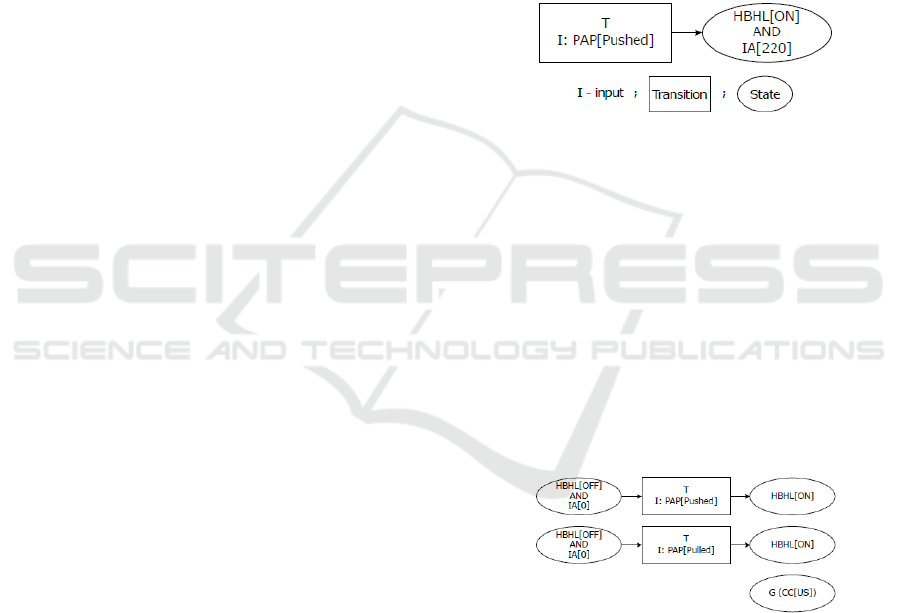
Def. 2 – Req. State Machine: A requirement FSM
represents exactly one textual described requirement
in form of a state machine.
Def. 3 – Atomic Req. State Machine: An atomic
requirement FSM represents one atomic requirement
as a state machine.
Def. 4 – System State Machine: System FSM
represents unity of all requirements for the system.
CC – Country Code; IA – Illuminated Range
PAP – PitArmPosition; HBHL – HighBeamHeadlights
Figure 2: Requirement FSM.
One requirement generates one requirement state
machine. Multiple information (e.g. ‘left’ & ‘right’)
can be combined in one requirement in SPS. To
aggregate the system FSM, a synthesis of the
generated atomic requirement FSMs is necessary.
(Walter et al. 2018) splits system synthesis into three
steps:
I - Atomization: Separation of requirement FSMs
into atomic requirement FSMs
Figure 3: Atomization - Atomic Requirement FSMs.
II - Minimization: Connection and minimization of
system FSM with three rules. 'Merge Transitions',
'Merge States' and 'Add Links’. Identical transitions
and identical states are merged. Links that can be
retrieved through logic dependencies are added.
III - Generalization: Generalization of local
requirements with global requirements
Executable State Machines Derived from Structured Textual Requirements - Connecting Requirements and Formal System Design
195
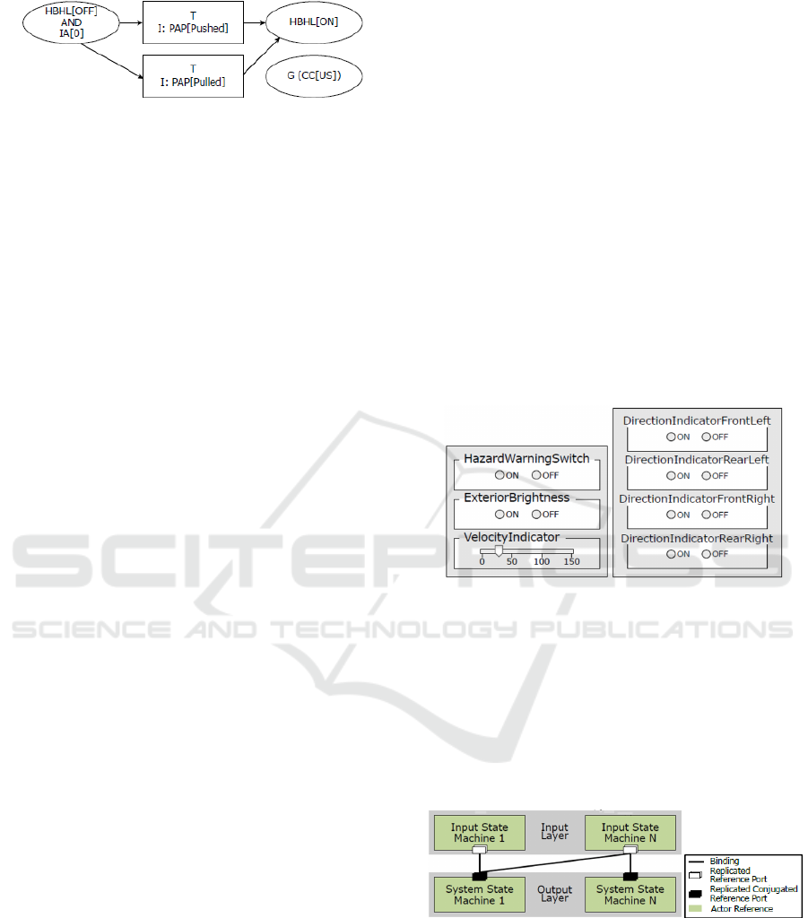
Figure 4: Minimization – System FSM.
Step II and Step III are applied in a loop until the
model is stable. Step III is performed with the same
approach described in Subsection 3.3. Each unique
path through the state machine is extracted and
checked against all global conditions. If the condition
is not yet included, the states and transitions of that
particular path are revised. The updated model is
checked for potential minimization in step II. This
loop eventually converges to a stable model. The
retrieved model is called system FSM. It is a static
representation of the system specified as structured
textual requirements in form of states and transitions.
Systems are generally dynamic. To replicate dynamic
behaviour of the actual system accurately, an
execution layer is included. Such layer enables the
model to show and simulate the dynamic operations.
In this section, we will discuss the implementation of
such an execution layer. This includes the model
structure, GUI for external data input, internal
processing and output.
4 DYNAMIC STATE MACHINE
A static system FSM represents the system specified
by the requirements. To makes such a model
executable, it requires two layers. An external
interaction layer with a GUI and output console as
well as an internal processing layer. This layer
contains the underlying logic and internal signal
transfers. The FSM is exported to ‘eTrice’ and both
layers are added to the existing ‘system FSM’.
4.1 External Interaction Layer
The external layer serves the purpose to control the
user inputs into the system FSM. The user (tester,
specification engineer, system designer) can change
parameters through a GUI as shown in Figure 5. This
triggers the internal processing layer. The parameters
displayed at the GUI, are all parameters that affect the
system to transition between states. The complete list
of GUI entries is created by crawling all transition
inputs for unique Parameter[StateValue]
combinations. Parameters are methodically split into
two classes. First, parameters for user interactions
(e.g. buttons). Second, parameters that observe the
environment (e.g. sensors). Buttons are intended for
user interaction. Sensors are used for passive
controlling.
Through internal logic, current state is
transitioned to a new current state and a signal with
an output message is sent. This output has to be
represented alongside the new current state.
Therefore, beside input control, the second purpose
of the external layer is displaying output messages.
In its simplest form, this can be performed through
console outputs shown in Figure 5. Next state and
output message are variables of the finite state
machine. In Moore DFSM next state is a function of
current state and transition logic. The internal
processing layer executes this function and returns
the next state to the console. In addition, output logic
which is a function of current state only, generates
the output message and returns that message to the
console.
Figure 5: External Interaction Layer (Input / Output).
4.2 Internal Interaction Layer
To make a FSM truly executable, user interaction
must be possible. It includes user input, processing
and system reaction as feedback. Parameters at
the input layer are parameters that occur in
transitions while parameters at the output layer
occur in states.
Figure 6: Communication Layer.
Def. 5 – Atomic FSM: An atomic FSM represents a
FSM for one parameter with all possible values (one
state per value) and all possible transitions. All other
FSMs (requirement, atomic requirement and system)
consist of combinations of atomic FSMs.
MODELSWARD 2019 - 7th International Conference on Model-Driven Engineering and Software Development
196

Implementation occurs in the way that each atomic
FSM is extended with its personal communication
layer. This makes the atomic FSM executable. Once
input changes a particular atomic FSM, atomic FSM
receives a message with new parameter[value] and
current state for the atomic FSM is changed. System
FSM cannot actively request current atomic FSM
states but receives push messages from the particular
atomic FSM once a change occurs. Start state,
therefore current state of system FSM is reset state.
Communicated input is compared with a transition
condition from current state to all connected states. If
fulfilled, system FSM changes its current state and
generates output (see: Figure. 6).
4.3 Execution Example
Overall, section 4 discussed all steps to answer RQ1
with qualitative examples. This is consolidated now
in one overall example. All graphical visualizations
of GUIs and FSM are represented in Figure 7.
Figure 7: Execution Example.
Initially input shows
HazardWarningSwitch[OFF]. Output shows all
DirectionIndicators as initially [OFF]. The current
state for the Atomic FSM and System FSM are in
accordance (Atomic FSM I is in state [OFF] and
System FSM is in state S
1
). User input changes
HazardWarningSwitch[ON]. The communication
layer broadcasts this change to the Atomic FSM
where current state is changed to [ON]. Further,
Atomic FSMs communicate changes to system FSM.
Here, the transition condition at current state is
checked. Since it is now fulfilled, current state is
adjusted from S
1
to S
2
. The corresponding output is
generated in the form that all DirectionIndicators turn
to [ON]. Again, the transition condition at the new
current state (S
2
) is checked. It is fulfilled, thus
current state changes back to S
1
with its
corresponding output of all DirectionIndicators equal
to [OFF]. Obviously, as long as the Atomic FSM is
in state [ON], the System FSM changes between S
1
and S
2
periodically. Transition condition of S
1
and S
2
are not fulfilled as soon as input changes
HazardWarningSwitch[OFF]. This change is broad-
casted to the Atomic FSM, which communicates this
change to System FSM. In this case all
DirectionIndicators remain [OFF].
5 APPLICATION
In this section, RQ2 is addressed. We show the
derived executable model in an industrial case study.
With the Adaptive Outside Light Control (AOLC)
a Mercedes-Benz Car Systems is investigated.
We show correctness of our executable model by
applying a set of test cases for functional
system tests against the model and comparing the
generated output messages to the expected results
for the test cases. Subsection 5.1 provides a brief
overview of the assumptions and requirements for
data and tool chain. Subsection 5.2 explains case
study and detailed approach. It is evaluated in
Subsection 5.3.
5.1 Assumptions
The AOLC system has to fulfil a set of conditions and
constraints: Requirements are represented in a
structured specification while test cases exist in a
structured test specification. All requirements and test
cases are tagged for the attribute 'object type' with
either 'requirement' or 'test case'. Linking between
requirements and test cases exists. Requirements,
tests cases and links are stored in a requirements
management tool with ReqIF file export (e.g. IBM
Rational Doors). The systems is initially represented
in natural language expressions. Requirements are
converted from text to SPS. Tests remain in natural
language. Textual representation prevents machine-
based processing, which is not needed in our case.
The static model is derived in Design Cockpit 43
(DC43), which is based on an Eclipse framework.
The executable model therefore is represented in the
Eclipse extension ‘eTrice’.
5.2 Setup and Approach
This section explains the data set of the AOLC
system, setup and approach used to generate the
Executable State Machines Derived from Structured Textual Requirements - Connecting Requirements and Formal System Design
197
results for the evaluation. We choose this system
based on availability. AOLC is a publicly available
set of requirements and tests of the original system. It
was investigated (Föcker et al., 2015 and Walter et
al., 2018) and is therefore already formalized in SPS.
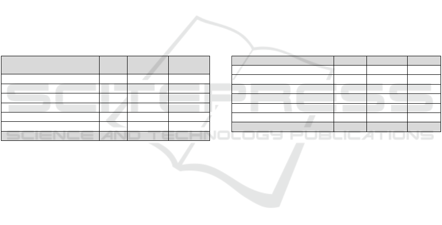
Table 1 shows the system in quantitative form. From
the full set of 50 requirements we only choose 38
functional requirements for the investigation. Data is
structured by functions. Each function contains
requirements and test cases that are linked to each
other. Overall, we consider 38 requirements and 38
test cases. Our approach for the given data set is to
derive the executable model and to apply the
specified test cases. The static model is based on the
functional requirements. The process generated a
system FSM with 47 system states and 256
transitions. Test cases are compared against output
generated for a specific system state. A test case
contains a set of steps (TS), where each step has a
precondition, action and pass condition. All tests are
represented in natural language.
Table 1: System metrics AOLC.
Function
Total
Req.
Func.
Req.
Test
Cases
Turn and Warning Sig. 21 15 20
Low Beam Headlight 9 6 7
Adapt. HB Headlights 9 9 2
Man. HB Headlights 2 2 2
Fault Detection 6 3 6
Headlight Technology 3 3 1
Total System 50 38 38
Linking between tests and requirement in addition
to the traceability between requirement and system
states, allows locating the system states related to a
particular test case. (Walter et al., 2018) showed
correctness and practicality of the generated static
system FSMs. We intend to verify the executable
machine by execution of the related buttons at the
GUI and comparing output to specified tests in a
black box test. The assumption is that requirements
and test cases are correct. We do not intend to test the
system specification but we show that the executable
machine represents the specification.
5.3 Evaluation
In this subsection we evaluate the case study. We
discuss our findings, comment on the results and
overall answer RQ2. Table 2 shows the quantitative
evaluation of the test steps. The results of test steps
are divided into three branches: Passed test steps,
blocked TS and failed TS. Passed test steps generate
the specified output. Starting with the precondition,
performing the given action and checking the pass
conditions. Passed tests are in alignment with the
approach and need no further discussion. Blocked
tests sequence of precondition, action and pass
condition which are not executable. A closer look at
these test steps and the reason for the blocking has
to be considered. Failed test steps are characterized
with incorrect output generation (pass condition)
after performing the specified action starting from
the specified precondition. Occurrences of failed TS
are critical and have to be reviewed to assure that
such a test does not challenge the overall
approach. Generally, 63 out of 80 test steps are
classified as passed test steps and therefore need no
further discussion. Eight test steps turned out to be
blocked. All eight of them, located in the vehicle
function ‘Turn and Warning Signalling', are blocked
due to a not yet fully developed interface to 'eTrice'.
The 'Bounded existence' pattern requires encoding
of a counter, which caused implementation
problems.
Table 2: Evaluation AOLC with test steps (TS).
Function Passed Blocked Failed
Turn and Warning Sig. 36 8 2
Low Beam Headlight 17 0 2
Adapt. HB Headlights 4 0 2
Man. HB Headlights 4 0 0
Fault Detection 2 0 3
Headlight Technology 0 0 0
Total System 63 8 9
A fully developed interface should change these
test steps to passed test steps. The failed test steps are
distributed among nearly all vehicle functions. A
case-wise review and analysis is required. Two failed
tests were caused by imprecise structuring of
requirements text at the manual transformation from
NL to SPS. The remaining seven test steps can be
traced back to incomplete specifications in the initial
text form. In conclusion, neither blocked nor failed
test steps are caused by our developed formalization
process. Our findings for the selected AOLC system
validate correctness of the generated system FSM. All
states and transitions are plausible. All blocked and
failed tests were caused by pre-processing errors or
‘eTrice’ limitations. Thus, our approach to derive
state machines from structured text with the provided
process seems valid.
6 LIMITATIONS
In this section we discuss limitations to our approach
and with this we answer RQ3. First we have to
MODELSWARD 2019 - 7th International Conference on Model-Driven Engineering and Software Development
198

address the general scope of the described approach.
The specification patterns we used are designed for
functional requirements. It is possible to include
certain non-functional requirements, but the majority
cannot be formalized in SPS. Informal knowledge is
a problem that exceeds the scope of this paper. We
therefore limit the overall approach to functional
requirements with the possibility to process selected
non-functional requirements. Regarding scale, we
observe multiple points to discuss: We see run time
for scaled systems as uncritical. Tasks like importing
scaled ReqIF data sets and generating industry sized
graphs were performed and did not cause extended
run times. More critical is readability for particular
states and its descriptions in scaled systems. The
shown application contained up to ten parameters for
a state description. In scaled systems this will
dramatically increase and might reduce human
readability drastically. One solution is to use this
approach mostly for machine based analysis. Second,
it is possible to investigate only reduced systems for
particular analysis by filtering the overall system for
particular parameters. This option maintains the
complexity and correctness of the represented system
FSM while focusing the analysis on the particular
parameters relevant. Last, we want to discuss scope.
We applied this approach only to the automotive light
domain, yet we strongly believe that other domains
can use this approach without adaptations. Once a
specification pattern can express a requirement, it can
be used for modelling. SPS were developed domain
independent. We showed work in the field of
automotive. Yet, we emphasize other fields to use this
approach. We see no hindrance to express
requirements of various domains in SPS and to derive
system FSMs. Pre-processing of requirements in SPS
and representation as system FSM should still be
reviewed by domain experts.
7 RELATED WORK
This work included previous work in various fields.
In the introduction, we discussed the structured
representation of requirements in form of
specification patterns. Common patterns are Master
(Sophist, 2018) EARS (Mavin and Wilkinson, 2009),
Volere (Robertson and Robertson, 2009) and
Specification Pattern Systems (SPS) (Dwyer et al.,
1998). SPS are tightly connected with linear temporal
logic. Linear temporal logic was initially described by
(Prior, 1967, and Kamp, 1968). Representation of
complex systems is often performed in form of state
machines. We used the work of (Kam et al., 2013) as
the foundation for finite state machines. The
connection between linear temporal logic and state
machines occurs through mapping. We based our
own mapping efforts on (Gastin and Oddoux, 2001,
Lu and Luo 2012 and Walter et al., 2018). To
represent derived state machines we use Design
Cockpit 43 as a software. Design Cockpit 43 is based
on design grammars. (Rudolph, 2006, Rudolph et al.,
2013, Alber et al., 2002) described the underlying
methodology of vocabularies, rule set, production
system and compiler. The Graph-based design
methodology paired with the described processing
chain, allows us to derive a consistent model from
textual requirements. The general idea for model
generation from structured text was provided by
(Walter et al., 2017) and extend here towards
executable models.
8 CONCLUSIONS AND
OUTLOOK
This paper showed an approach to formally process
structured textual requirements into executable finite
state machines. The process chain from textual requi-
rement representation to system creation is often not
continuous and contains gaps. This leads to informal
decision making throughout the process and signify-
cantly limits the exploration of the solution space
during system design. Our approach bridges that gap
by providing a systematic transformation chain that
generates a formally correct executable representation
of the system specified through its requirements. We
see this as a valuable support for specification and
system design. The approach limits manual decision
making in steps where decisions can be formally
derived. It allows specification engineers and system
design engineers to evaluate what consequences and
design constraints arise from creation or adjustment of
a particular requirement. Execution of the derived state
machine enables engineers to expose missing states
and transitions, non-deterministic behaviours and
inconsistencies in their specification or design. In this
setup, an executable FSM serves as a model in the loop
(MIL). Specifications can be adjusted and changes in
the system can be evaluated instantly. We provide a
qualitative example and a quantitative case study to
show applicability in industrial setups. This work
provides the basis for further applications. We would
like to show scalability and intend to add further
system design steps towards a requirement driven
digital design process for complex (automotive)
systems.
Executable State Machines Derived from Structured Textual Requirements - Connecting Requirements and Formal System Design
199

ACKNOWLEDGEMENTS
We want to thank our collaborators at Daimler AG:
Frank Houdek, Marco Piechotta and Jakob Hammes
in the testing department for their input, help with
data set and system knowledge for the case study.
REFERENCES
Alber, R., Rudolph S., Kröplin, B. "On Formal Languages
in Design Generation and Evolution." 5th World
Congress on Comp. Mechanics, 2002.
Alber, R., Rudolph, S.”43 - A Generic Approach for
Engineering Design Grammars.” AAAI Spring Symposium
Computational Synthesis, 2003.
Alber, R, Rudolph, S. "On a Grammar-Based Design
Language that Supports Automated Design Generation
and Creativity." In Knowledge Intensive Design
Technology, Springer, 2004.
Artale, A, Franconi, E. "A Temporal Description Logic for
Reasoning about Actions and Pans." Journal of
Artificial Intelligence Research, 1998.
Artale, A.. ”Linear Temporal Logic.” LectureNotes:
Formal Methods Lecture III, 2010.
Bühler, D., Minker, W. “Domain-Level Reasoning for
Spoken Dialogue Systems. Springer Science, 2011.
Clarke, E., Emerson, A., Sistla, P.”Automatic Verification
of Finite-State Concurrent Systems Using Temporal
Logic Specifications.” ACM, Transactions on
Programming Languages & Systems (TOPLAS), 1986.
Czerwinski, R, Kania, D.”Finite State Machine Logic
Synthesis for Complex Programmable Logic Devices”.
Springer Science, 2013.
Dwyer, M., Avrunin, G., Corbett, J.”Property Specification
Patterns for Finite-State Verification.” In Proceedings
of the Second Workshop on Formal Methods in
Software Practice, ACM, 1998.
Dwyer, M., Avrunin, G., Corbett, J. "Patterns in Property
Specifications for Finite-State Verification." Software
Engineering, 1999.
Föcker, F., Houdek, F., Daun, M., Weyer. T., ”Model-
Based Engineering of an Automotive Adaptive Exterior
Lighting System: Realistic Example Specifications of
Behavioural Requirements and Functional Design.”,
2015.
Gabbay, D., Pnueli, A., Shelah, S., Stav, J. ”On the
Temporal Analysis of Fairness.” In Proceedings of the
7th ACM SIGPLAN-SIGACT Symposium on Principles
of Programming Languages, ACM, 1980.
Gastin, P., Oddoux, D.”Fast LTL to Büchi Automata
Translation.” In International Conference on Computer
Aided Verification, Springer, 2001.
Glinz, M.. ”On Non-Functional Requirements.” In
Requirements Engineering Conference, 2007.
IILS mbH, "Design Cockpit 43" http://iils.de (05/ 2018).
IILS mbH,”Total Engineering Automation Vision and
Realization with Graph-based Design Languages and
the Design Cockpit 43.” http://iils.de, (05/2018).
ISO/IEC/IEEE 29148: 2011(E): ISO/IEC/IEEE Int.
Standard, Systems & Software Engineering Life Cycle
Processes Requirements Engineering. IEEE, 2011.
Etrice, Eclipse Plugin. https://www.eclipse.org/etrice/,
(02/2018).
Kamp, H. ”Tense Logic and the Theory of Linear Order.”,
1968.
Kam, T., Villa, T., Brayton, R., Sangiovanni-Vincentelli, A.
"Synthesis of Finite State Machines: Functional
Optimization." Springer Science, 2013.
Lu, X., Luo, G. ”Direct Translation of LTL Formulas to
Büchi Automata.” In Cognitive Informatics &
Cognitive Computing, 2012.
Maalej, W. Thurimella, A. “Managing Requirements
Knowledge, 2013.
Mavin, Alistair, Wilkinson, P. "Big Ears (The Return of
"Easy Approach to Requirements Engineering")." In
Requirements Engineering Conference, 2010.
Mavin, A., Wilkinson, P., Harwood, A., Novak, M. ”Easy
Approach to Requirements Syntax (EARS).” In
Requirements Engineering Conference IEEE, 2009.
Pahl, G, Beitz, W. ”Engineering Design: A Systematic
Approach.” Springer Science, 2013.
Prior, A. ”Past, Present and Future.” Oxford: Clarendon
Press, 1967.
Robertson, J., Robertson, S. ”Volere Requirements
Specification Template.”, 2009.
Rudolph, S.”A Semantic Validation Scheme for Graph-
Based Engineering Design Grammars.” In Design
Computing and Cognition06, Springer, 2006.
Rudolph, S., Beichter, J., Eheim M., Hess, S., Motzer, M.,
Weil, R. "On Multi-Disciplinary Architectural
Synthesis and Analysis of Complex Systems with
Graph-Based Design Languages." DGLR, 2013.
Sophist GmbH:”MASTeR Schablonen für alle Fälle” 2016
Spillner, A., Linz, T., ”Basiswissen Softwaretest”,
dpunkt.Verlag GmbH, 2005.
Villa, T., Kam, T., Brayton, R., Sangiovanni-Vincentelli, A.
”Synthesis of Finite State Machines: Logic
Optimization.” Springer Science, 2012.
Walter, B., Hammes, J., Piechotta, M., Rudolph, S.”A
Formalization Method to Process Structured Natural
Language to Logic Expressions to Detect Redundant
Specification and Test Statements.” In Requirements
Engineering Conference (RE), IEEE, 2017.
Walter, B., Schilling M., Piechotta, M., Rudolph, S.
”Improving Test Execution Efficiency through
Clustering and Reordering of Independent Test Steps.
„Software Testing, Verification & Validation, 2018.
Walter, B., Martin, J., Rudolph, S. ”A Method to
Automatically Derive the System State Machine from
Structured Natural Language Requirements through
Requirements Formalization.” INCOSE, 2018.
MODELSWARD 2019 - 7th International Conference on Model-Driven Engineering and Software Development
200
